Page 1309 of 2898
7 CHECK POWER SUPPLY
1. Stop engine.
2. Turn ªOFFº the rear window defogger switch.
3. Disconnect rear window defogger relay.
4. Check voltage between terminal 3 (LHD models), 5 (RHD models) and ground with CONSULT-II or tester.
SEF626Z
OK or NG
OK©GO TO 8.
NG©Check the following and repair.
+20A fuse
+Harness for open and short between fuse block and rear window defogger relay
8 CHECK REAR WINDOW DEFOGGER RELAY
Refer to ªComponent Inspectionº, EC-590.
OK or NG
OK©GO TO 9.
NG©Replace rear window defogger relay.
9 CHECK REAR WINDOW DEFOGGER INPUT SIGNAL CIRCUIT
1. Disconnect ECM harness connector.
2. Check harness continuity between ECM terminal 50 and rear window defogger relay terminals 5 (LHD models), 3 (RHD
models).
Refer to wiring diagram.
SEF627Z
3. Also check harness for short to ground and short to power.
OK or NG
OK©GO TO 11.
NG©GO TO 10.
ELECTRICAL LOAD SIGNALQG
Diagnostic Procedure Ð Load Signal Ð (Cont'd)
EC-585
Page 1314 of 2898

2 CHECK INPUT SIGNAL CIRCUIT
1. Stop engine.
2. Disconnect ECM harness connector.
3. Disconnect heater control panel fan switch harness connector.
4. Check harness continuity between ECM terminal 51 and heater fan switch harness connector terminal 18.
Refer to wiring diagram.
Continuity should exist.
5. Also check harness for short to ground and short to power.
OK or NG
OK©Refer to HA-48, ªBLOWER MOTORº.
NG©GO TO 3.
3 DETECT MALFUNCTIONING PART
Check the following.
+Harness connectors M94, F106 (Sedan)
+Harness connectors M73, F111 or M169, F113 (Hatchback)
+Harness for open and short between ECM and heater fan motor switch
©Repair open circuit or short to ground or short to power in harness or connectors.
SEF145XC
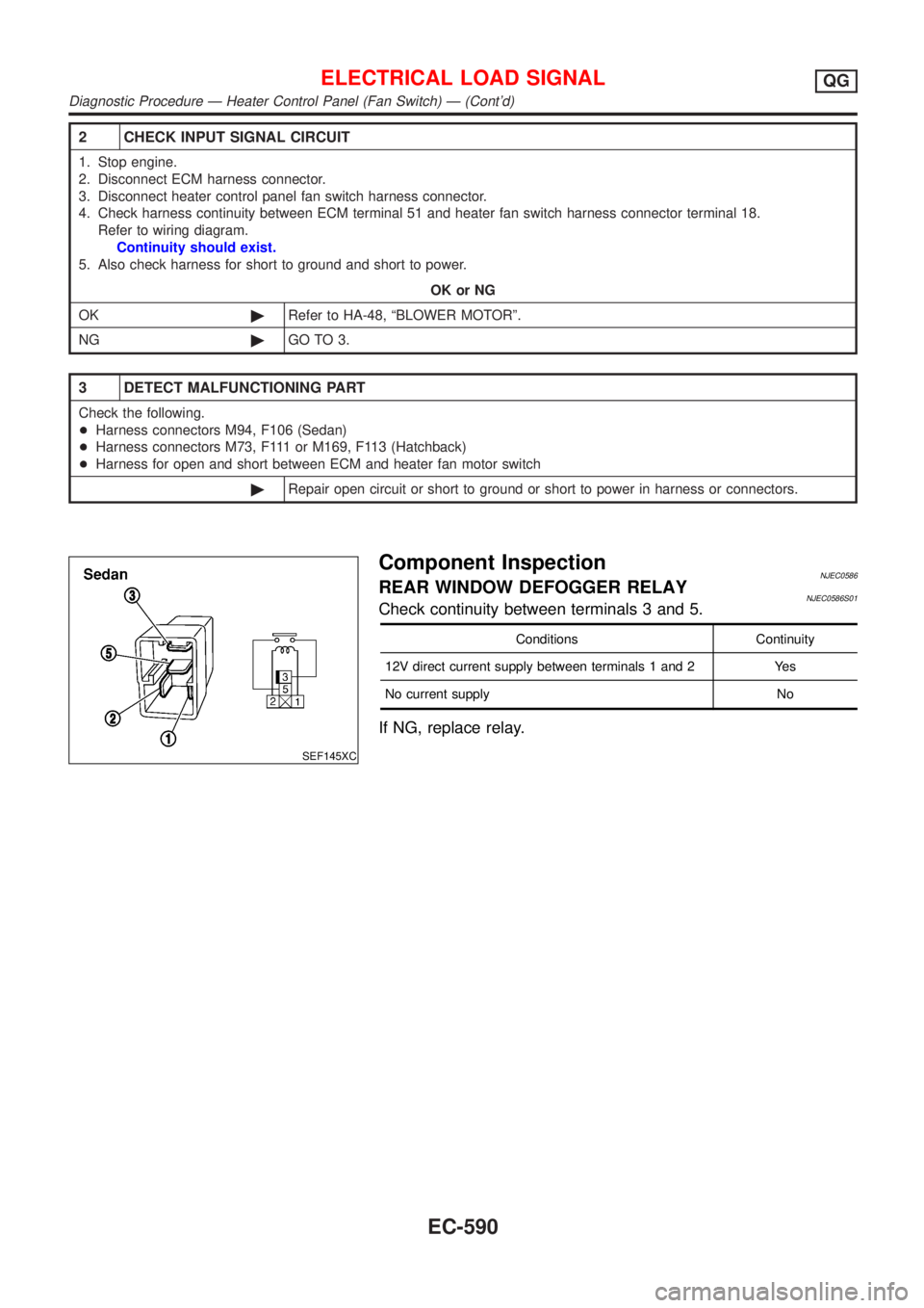
Component InspectionNJEC0586REAR WINDOW DEFOGGER RELAYNJEC0586S01Check continuity between terminals 3 and 5.
Conditions Continuity
12V direct current supply between terminals 1 and 2 Yes
No current supply No
If NG, replace relay.
ELECTRICAL LOAD SIGNALQG
Diagnostic Procedure Ð Heater Control Panel (Fan Switch) Ð (Cont'd)
EC-590
Page 1315 of 2898
Wiring DiagramNJEC0466SEDAN MODELS AND HATCHBACK MODELS WITH
ECM IN ENGINE COMPARTMENT
NJEC0466S01
HEC894
MI & DATA LINK CONNECTORSQG
Wiring Diagram
EC-591
Page 1316 of 2898
HATCHBACK MODELS WITH ECM IN CABINNJEC0466S02
HEC980
MI & DATA LINK CONNECTORSQG
Wiring Diagram (Cont'd)
EC-592
Page 1322 of 2898

Supplemental Restraint System (SRS) ªAIR
BAGº and ªSEAT BELT PRE-TENSIONERº
NJEC0601The Supplemental Restraint System such as ªAIR BAGº and ªSEAT BELT PRE-TENSIONERº used along with
a seat belt, helps to reduce the risk or severity of injury to the driver and front passenger for certain types of
collision. The SRS system composition which is available to NISSAN MODEL N16 is as follows (The compo-
sition varies according to the destination and optional equipment.):
+For a frontal collision
The Supplemental Restraint System consists of driver air bag module (located in the center of the steer-
ing wheel), front passenger air bag module (located on the instrument panel on passenger side), front seat
belt pre-tensioners, a diagnosis sensor unit, warning lamp, wiring harness and spiral cable.
+For a side collision
The Supplemental Restraint System consists of front side air bag module (located in the outer side of front
seat), side air bag (satellite) sensor, diagnosis sensor unit (one of components of air bags for a frontal
collision), wiring harness, warning lamp (one of components of air bags for a frontal collision).
Information necessary to service the system safely is included in theRS sectionof this Service Manual.
WARNING:
+To avoid rendering the SRS inoperative, which could increase the risk of personal injury or death
in the event of a collision which would result in air bag inflation, all maintenance should be per-
formed by an authorized NISSAN dealer.
+Improper maintenance, including incorrect removal and installation of the SRS, can lead to per-
sonal injury caused by unintentional activation of the system. For removal of Spiral Cable and Air
Bag Module, see the RS section.
+Do not use electrical test equipment on any circuit related to the SRS unless instructed to in this
Service Manual. SRS wiring harness can be identified by yellow harness connector.
PRECAUTIONSYD
Supplemental Restraint System (SRS) ªAIR BAGº and ªSEAT BELT PRE-TENSIONERº
EC-598
Page 1325 of 2898
SEF348N
+When measuring ECM signals with a circuit tester, never
allow the two tester probes to contact.
Accidental contact of probes will cause a short circuit and
damage the ECM power transistor.
+Do not use ECM ground terminals when measuring input/
output voltage. Doing so may result in damage to the
ECM's transistor. Use a ground other than ECM terminals,
such as the ground.
+Install the break-out box between ECM and ECM harness
connectors when measuring ECM input/output voltage.
Wiring Diagrams and Trouble DiagnosisNJEC0604When you read Wiring diagrams, refer to the following:
+GI-11, ªHOW TO READ WIRING DIAGRAMSº
+EL-10, ªPOWER SUPPLY ROUTINGº for power distribution circuit
When you perform trouble diagnosis, refer to the following:
+GI-32, ªHOW TO FOLLOW TEST GROUPS IN TROUBLE DIAGNOSESº
+GI-21, ªHOW TO PERFORM EFFICIENT DIAGNOSIS FOR AN ELECTRICAL INCIDENTº
PRECAUTIONSYD
Precautions (Cont'd)
EC-601
Page 1361 of 2898

SEF858S
SEF233G
SEF234G
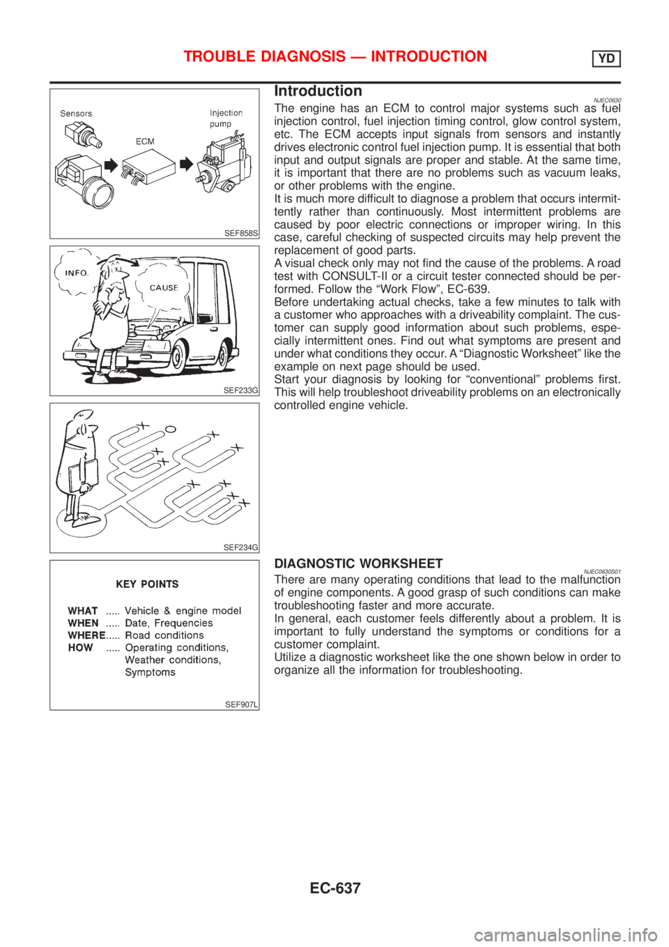
IntroductionNJEC0630The engine has an ECM to control major systems such as fuel
injection control, fuel injection timing control, glow control system,
etc. The ECM accepts input signals from sensors and instantly
drives electronic control fuel injection pump. It is essential that both
input and output signals are proper and stable. At the same time,
it is important that there are no problems such as vacuum leaks,
or other problems with the engine.
It is much more difficult to diagnose a problem that occurs intermit-
tently rather than continuously. Most intermittent problems are
caused by poor electric connections or improper wiring. In this
case, careful checking of suspected circuits may help prevent the
replacement of good parts.
A visual check only may not find the cause of the problems. A road
test with CONSULT-II or a circuit tester connected should be per-
formed. Follow the ªWork Flowº, EC-639.
Before undertaking actual checks, take a few minutes to talk with
a customer who approaches with a driveability complaint. The cus-
tomer can supply good information about such problems, espe-
cially intermittent ones. Find out what symptoms are present and
under what conditions they occur. A ªDiagnostic Worksheetº like the
example on next page should be used.
Start your diagnosis by looking for ªconventionalº problems first.
This will help troubleshoot driveability problems on an electronically
controlled engine vehicle.
SEF907L
DIAGNOSTIC WORKSHEETNJEC0630S01There are many operating conditions that lead to the malfunction
of engine components. A good grasp of such conditions can make
troubleshooting faster and more accurate.
In general, each customer feels differently about a problem. It is
important to fully understand the symptoms or conditions for a
customer complaint.
Utilize a diagnostic worksheet like the one shown below in order to
organize all the information for troubleshooting.
TROUBLE DIAGNOSIS Ð INTRODUCTIONYD
EC-637
Page 1364 of 2898

DESCRIPTION FOR WORK FLOWNJEC0631S01
STEP DESCRIPTION
STEP IGet detailed information about the conditions and the environment when the incident/symptom occurred using
the ªDIAGNOSTIC WORKSHEETº, EC-637.
STEP IIBefore confirming the concern, check and write down (print out using CONSULT-II) the DTC, then erase the
DTC. Refer to EC-627.
If the incident cannot be verified, perform ªTROUBLE DIAGNOSIS FOR INTERMITTENT INCIDENTº, EC-665.
Study the relationship between the cause, specified by DTC, and the symptom described by the customer. (The
ªSymptom Matrix Chartº will be useful. Refer to EC-646.) Also check related service bulletins for information.
STEP IIITry to confirm the symptom and under what conditions the incident occurs.
The ªDIAGNOSTIC WORK SHEETº is useful to verify the incident. Connect CONSULT-II to the vehicle in DATA
MONITOR (AUTO TRIG) mode and check real time diagnosis results.
If the incident cannot be verified, perform ªTROUBLE DIAGNOSIS FOR INTERMITTENT INCIDENTº, EC-665.
If the malfunction code is detected, skip STEP IV and perform STEP V.
STEP IVTry to detect the DTC by driving in (or performing) the ªDTC Confirmation Procedureº. Check and read the DTC
by using CONSULT-II.
During the DTC verification, be sure to connect CONSULT-II to the vehicle in DATA MONITOR (AUTO TRIG)
mode and check real time diagnosis results.
If the incident cannot be verified, perform ªTROUBLE DIAGNOSIS FOR INTERMITTENT INCIDENTº, EC-665.
In case the ªDTC Confirmation Procedureº is not available, perform the ªOverall Function Checkº instead. The
DTC cannot be displayed by this check, however, this simplified ªcheckº is an effective alternative.
The ªNGº result of the ªOverall Function Checkº is the same as the DTC detection.
STEP VTake the appropriate action based on the results of STEP I through IV.
If the malfunction code is indicated, proceed to TROUBLE DIAGNOSIS FOR DTC PXXXX.
If the normal code is indicated, proceed to the Basic Inspection, EC-641. Then perform inspections according to
the Symptom Matrix Chart. Refer to EC-646.
STEP VIIdentify where to begin diagnosis based on the relationship study between symptom and possible causes.
Inspect the system for mechanical binding, loose connectors or wiring damage using (tracing) ªHarness Layoutsº.
Gently shake the related connectors, components or wiring harness with CONSULT-II set in ªDATA MONITOR
(AUTO TRIG)º mode.
Check the voltage of the related ECM terminals or monitor the output data from the related sensors with CON-
SULT-II. Refer to EC-659 or EC-656.
The ªDiagnostic Procedureº in EC section contains a description based on open circuit inspection. A short circuit
inspection is also required for the circuit check in the Diagnostic Procedure. For details, refer to GI-24, ªCircuit
Inspectionº.
Repair or replace the malfunction parts.
If the malfunctioning part cannot be detected, perform ªTROUBLE DIAGNOSIS FOR INTERMITTENT
INCIDENTº, EC-665.
STEP VIIOnce you have repaired the circuit or replaced a component, you need to run the engine in the same conditions
and circumstances which resulted in the customer's initial complaint.
Perform the ªDTC Confirmation Procedureº and confirm the normal code (DTC P0000 or 0505) is detected. If the
incident is still detected in the final check, perform STEP VI by using a different method from the previous one.
Before returning the vehicle to the customer, be sure to erase the unnecessary (already fixed) DTC in ECM.
(Refer to EC-627.)
TROUBLE DIAGNOSIS Ð INTRODUCTIONYD
Work Flow (Cont'd)
EC-640