Page 1977 of 2898
USER ACTION TCU Reaction COMPONENT TESTED
Lighting switch turned 1st position or 2nd
position from offHazard flash once Tail lamp signal
Key put in ignition from out Hazard flash once Key in detect signal
Door lock/unlock switch is pressed Hazard flash once Central door lock/unlock signal
*) Hazard may flash a second time because of Driver's door status signal change. The min. delay time between flash actions is 100
ms.
In case the system does not operate as described above, check the concerned circuit for open or short. After
completion, the Diagnostic Mode can be switched off by pressing the rear defogger switch or by turning the
ignition to ªONº. The hazard lamp will flash at 3 Hz for 3 seconds to confirm that Diagnostic Mode has been
switched off.
TIME CONTROL UNIT
Trouble Diagnoses/Hatchback (Cont'd)
EL-419
Page 2133 of 2898

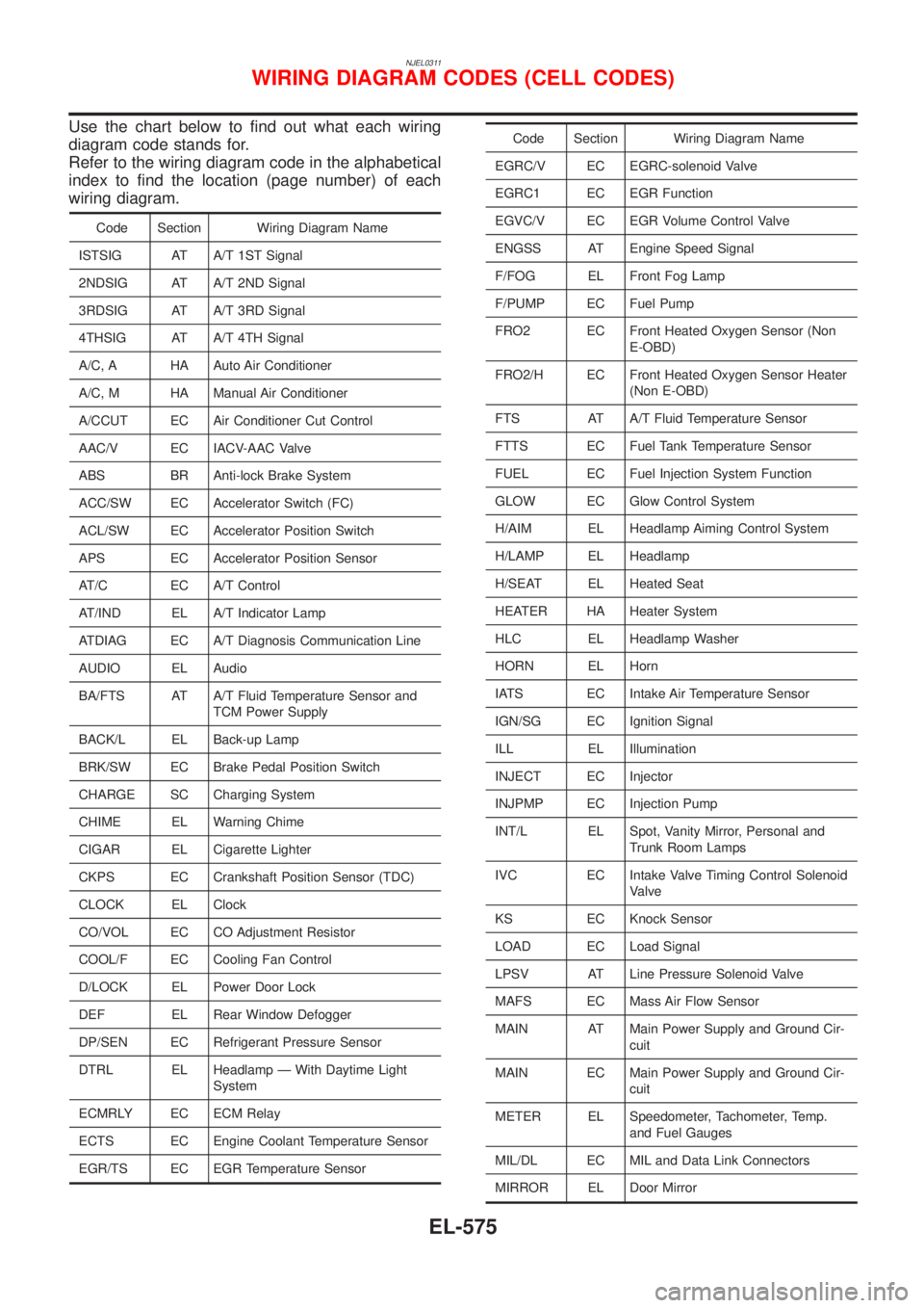
NJEL0311
Use the chart below to find out what each wiring
diagram code stands for.
Refer to the wiring diagram code in the alphabetical
index to find the location (page number) of each
wiring diagram.
Code Section Wiring Diagram Name
ISTSIG AT A/T 1ST Signal
2NDSIG AT A/T 2ND Signal
3RDSIG AT A/T 3RD Signal
4THSIG AT A/T 4TH Signal
A/C, A HA Auto Air Conditioner
A/C, M HA Manual Air Conditioner
A/CCUT EC Air Conditioner Cut Control
AAC/V EC IACV-AAC Valve
ABS BR Anti-lock Brake System
ACC/SW EC Accelerator Switch (FC)
ACL/SW EC Accelerator Position Switch
APS EC Accelerator Position Sensor
AT/C EC A/T Control
AT/IND EL A/T Indicator Lamp
ATDIAG EC A/T Diagnosis Communication Line
AUDIO EL Audio
BA/FTS AT A/T Fluid Temperature Sensor and
TCM Power Supply
BACK/L EL Back-up Lamp
BRK/SW EC Brake Pedal Position Switch
CHARGE SC Charging System
CHIME EL Warning Chime
CIGAR EL Cigarette Lighter
CKPS EC Crankshaft Position Sensor (TDC)
CLOCK EL Clock
CO/VOL EC CO Adjustment Resistor
COOL/F EC Cooling Fan Control
D/LOCK EL Power Door Lock
DEF EL Rear Window Defogger
DP/SEN EC Refrigerant Pressure Sensor
DTRL EL Headlamp Ð With Daytime Light
System
ECMRLY EC ECM Relay
ECTS EC Engine Coolant Temperature Sensor
EGR/TS EC EGR Temperature Sensor
Code Section Wiring Diagram Name
EGRC/V EC EGRC-solenoid Valve
EGRC1 EC EGR Function
EGVC/V EC EGR Volume Control Valve
ENGSS AT Engine Speed Signal
F/FOG EL Front Fog Lamp
F/PUMP EC Fuel Pump
FRO2 EC Front Heated Oxygen Sensor (Non
E-OBD)
FRO2/H EC Front Heated Oxygen Sensor Heater
(Non E-OBD)
FTS AT A/T Fluid Temperature Sensor
FTTS EC Fuel Tank Temperature Sensor
FUEL EC Fuel Injection System Function
GLOW EC Glow Control System
H/AIM EL Headlamp Aiming Control System
H/LAMP EL Headlamp
H/SEAT EL Heated Seat
HEATER HA Heater System
HLC EL Headlamp Washer
HORN EL Horn
IATS EC Intake Air Temperature Sensor
IGN/SG EC Ignition Signal
ILL EL Illumination
INJECT EC Injector
INJPMP EC Injection Pump
INT/L EL Spot, Vanity Mirror, Personal and
Trunk Room Lamps
IVC EC Intake Valve Timing Control Solenoid
Valve
KS EC Knock Sensor
LOAD EC Load Signal
LPSV AT Line Pressure Solenoid Valve
MAFS EC Mass Air Flow Sensor
MAIN AT Main Power Supply and Ground Cir-
cuit
MAIN EC Main Power Supply and Ground Cir-
cuit
METER EL Speedometer, Tachometer, Temp.
and Fuel Gauges
MIL/DL EC MIL and Data Link Connectors
MIRROR EL Door Mirror
WIRING DIAGRAM CODES (CELL CODES)
EL-575
Page 2419 of 2898
Control OperationNJHA0123
RHA747H
FAN CONTROL SWITCHNJHA0123S01This switch turns the fan ON and OFF, and controls fan speed.
MODE CONTROL KNOBNJHA0123S02This knob controls the outlet air flow.
TEMPERATURE CONTROL KNOBNJHA0123S03This knob allows you to adjust the temperature of the discharge air.
REAR WINDOW DEFOGGER SWITCHNJHA0123S07When illumination is ON, rear window is defogged.
AIR CONDITIONER (A/C) SWITCHNJHA0123S05The air conditioner switch controls the A/C system. When the switch is depressed with the fan ON, the com-
pressor will turn ON. The indicator lamp will also light.
The air conditioner cooling function operates only when the engine is running.
RECIRCULATION (REC) SWITCHNJHA0123S08Recirculation (REC) position: Interior air is recirculated inside the vehicle. (The indicator lamp will light.)
Fresh (FRE) position: Outlet air is drawn into the passenger compartment. (The indicator lamp will not light.)
DESCRIPTION
Control Operation
HA-19
Page:
< prev 1-8 9-16 17-24