Page 820 of 2898

MEF036D
SEF233G
SEF234G
IntroductionNJEC0036The engine has an ECM to control major systems such as fuel
control, ignition control, idle air control system, etc. The ECM
accepts input signals from sensors and instantly drives actuators.
It is essential that both input and output signals are proper and
stable. At the same time, it is important that there are no problems
such as vacuum leaks, fouled spark plugs, or other problems with
the engine.
It is much more difficult to diagnose a problem that occurs intermit-
tently rather than continuously. Most intermittent problems are
caused by poor electric connections or improper wiring. In this
case, careful checking of suspected circuits may help prevent the
replacement of good parts.
A visual check only may not find the cause of the problems. A road
test with CONSULT-II (or GST) or a circuit tester connected should
be performed. Follow the ªWork Flowº on EC-98.
Before undertaking actual checks, take a few minutes to talk with
a customer who approaches with a driveability complaint. The cus-
tomer can supply good information about such problems, espe-
cially intermittent ones. Find out what symptoms are present and
under what conditions they occur. A ªDiagnostic Worksheetº like the
example on next page should be used.
Start your diagnosis by looking for ªconventionalº problems first.
This will help troubleshoot driveability problems on an electronically
controlled engine vehicle.
SEF907L
DIAGNOSTIC WORKSHEETNJEC0036S01There are many operating conditions that lead to the malfunction
of engine components. A good grasp of such conditions can make
trouble-shooting faster and more accurate.
In general, each customer feels differently about a problem. It is
important to fully understand the symptoms or conditions for a
customer complaint.
Utilize a diagnostic worksheet like the one on the next page in order
to organize all the information for troubleshooting.
Some conditions may cause the malfunction indicator lamp to
come on steady or blink and DTC to be detected.
Example:
Vehicle ran out of fuel, which caused the engine to misfire.
TROUBLE DIAGNOSIS Ð INTRODUCTIONQG
EC-96
Page 827 of 2898
9 CHECK THROTTLE VALVE OPERATION
1. Remove intake air ducts.
2. Check throttle valve operation when moving throttle drum by hand.
OK or NG
OK©1. Retighten the throttle drum fixing nuts.
2. GO TO 7.
NG©1. Clean the throttle body and throttle valve.
2. GO TO 7.
10 CHECK THROTTLE POSITION SWITCH CLOSED POSITION-I
NOTE:
Always check ignition timing before performing the following.
1. Warm up engine to normal operating temperature.
2. Stop engine.
3. Remove the vacuum hose connected to the throttle opener.
4. Connect suitable vacuum hose to vacuum pump as shown below.
SEF793WA
5. Apply vacuum [more than þ40.0 kPa (±400 mbar, þ300 mmHg, þ11.81 inHg)] until the throttle drum is free from the
throttle opener rod.
Models with CONSULT-II©GO TO 11.
Models without CON-
SULT-II©GO TO 15.
TROUBLE DIAGNOSIS Ð BASIC INSPECTIONQG
Basic Inspection/Sedan (Cont'd)
EC-103
Page 828 of 2898
11 CHECK THROTTLE POSITION SWITCH CLOSED POSITION-II
With CONSULT-II
1. Connect ªCONSULT-IIº to the data link connector and select ªENGINEº from the menu. Refer to EC-83.
2. Turn ignition switch ªONº.
3. Select ªTP SW/TP SEN IDLE POSI ADJº in ªWORK SUPPORTº mode with CONSULT-II.
4. Read ªCLSD THL/P SWº signal under the following conditions.
+Insert a 0.05 mm (0.0020 in) and 0.15 mm (0.0059 in) feeler gauge alternately between stopper and throttle drum as
shown in the figure and check the signal.
SEF073X
SEF715Y
ªCLSD THL/P SWº signal should remain ªONº while inserting 0.05 mm (0.0020 in) feeler gauge.
ªCLSD THL/P SWº signal should remain ªOFFº while inserting 0.15 mm (0.0059 in) feeler gauge.
OK or NG
OK©GO TO 14.
NG©GO TO 12.
TROUBLE DIAGNOSIS Ð BASIC INSPECTIONQG
Basic Inspection/Sedan (Cont'd)
EC-104
Page 831 of 2898
14 RESET THROTTLE POSITION SENSOR IDLE POSITION MEMORY
With CONSULT-II
NOTE:
Always warm up engine to normal operating temperature. If engine is cool, the throttle position sensor idle posi-
tion memory will not be reset correctly.
1. Confirm that proper vacuum is applied. Refer to Test No. 10.
2. Attach blind cap to vacuum port from which vacuum hose to throttle opener was disconnected.
3. Start engine.
4. Warm up engine to normal operating temperature.
5. Select ªTP SW/TP SEN IDLE POSI ADJº in ªWORK SUPPORTº mode.
6. Stop engine. (Turn ignition switch ªOFFº.)
7. Turn ignition switch ªONº and wait at least 5 seconds.
SEF864V
8. Turn ignition switch ªOFFº and wait at least 9 seconds.
9. Repeat steps 7 and 8 until ªCLSD THL POSº signal changes to ªONº.
SEF715Y
©GO TO 19.
TROUBLE DIAGNOSIS Ð BASIC INSPECTIONQG
Basic Inspection/Sedan (Cont'd)
EC-107
Page 834 of 2898

17 ADJUSTMENT THROTTLE POSITION SWITCH CLOSED POSITION-II
Without CONSULT-II
1. Temporarily tighten sensor body fixing bolts as follows.
+Gradually move the sensor body clockwise and stop it when the continuity comes to exist, then temporarily
tighten sensor body fixing bolts.
SEF964W
2. Make sure two or three times that the continuity exists when the throttle valve is closed and continuity does not exist
when it is opened.
3. Remove 0.05 mm (0.0020 in) feeler gauge then insert 0.15 mm (0.0059 in) feeler gauge.
4. Make sure two or three times that the continuity does not exist when the throttle valve is closed.
5. Tighten throttle position sensor.
6. Check the continuity again.
Continuity does not exist while closing the throttle valve.
OK or NG
OK©GO TO 18.
NG©GO TO 16.
18 RESET THROTTLE POSITION SENSOR IDLE POSITION MEMORY
Without CONSULT-II
NOTE:
Always warm up engine to normal operating temperature. If engine is cool, the throttle position sensor idle posi-
tion memory will not be reset correctly.
1. Confirm that proper vacuum is applied. Refer to Test No. 10.
2. Attach blind cap to vacuum port from which vacuum hose to throttle opener was disconnected.
3. Start engine.
4. Warm up engine to normal operating temperature.
5. Stop engine. (Turn ignition switch ªOFFº.)
6. Turn ignition switch ªONº and wait at least 5 seconds.
SEF864V
7. Turn ignition switch ªOFFº and wait at least 9 seconds.
8. Repeat steps 6 and 7, 20 times.
©GO TO 19.
TROUBLE DIAGNOSIS Ð BASIC INSPECTIONQG
Basic Inspection/Sedan (Cont'd)
EC-110
Page 835 of 2898

19 CHECK (1ST TRIP) DTC
1. Turn ignition switch ªOFFº.
2. Release vacuum from throttle opener.
3. Remove vacuum pump and vacuum hose from throttle opener.
4. Reinstall original vacuum hose to throttle opener securely.
5. Start engine and warm it up to normal operating temperature.
6. Rev (2,000 to 3,000 rpm) two or three times.
7. Make sure no (1st trip) DTC is displayed with CONSULT-II or GST.
OK or NG
OK©GO TO 21.
NG©GO TO 20.
20 REPAIR MALFUNCTION
Repair or replace components as necessary according to corresponding ªDiagnostic Procedureº.
©GO TO 19.
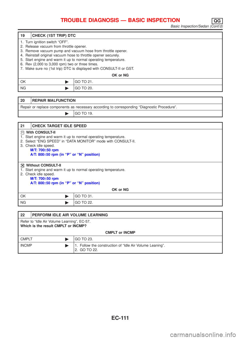
21 CHECK TARGET IDLE SPEED
With CONSULT-II
1. Start engine and warm it up to normal operating temperature.
2. Select ªENG SPEEDº in ªDATA MONITORº mode with CONSULT-II.
3. Check idle speed.
M/T: 700±50 rpm
A/T: 800±50 rpm (in ªPº or ªNº position)
Without CONSULT-II
1. Start engine and warm it up to normal operating temperature.
2. Check idle speed.
M/T: 700±50 rpm
A/T: 800±50 rpm (in ªPº or ªNº position)
OK or NG
OK©GO TO 31.
NG©GO TO 22.
22 PERFORM IDLE AIR VOLUME LEARNING
Refer to ªIdle Air Volume Learningº, EC-57.
Which is the result CMPLT or INCMP?
CMPLT or INCMP
CMPLT©GO TO 23.
INCMP©1. Follow the construction of ªIdle Air Volume Leaningº.
2. GO TO 22.
TROUBLE DIAGNOSIS Ð BASIC INSPECTIONQG
Basic Inspection/Sedan (Cont'd)
EC-111
Page 836 of 2898

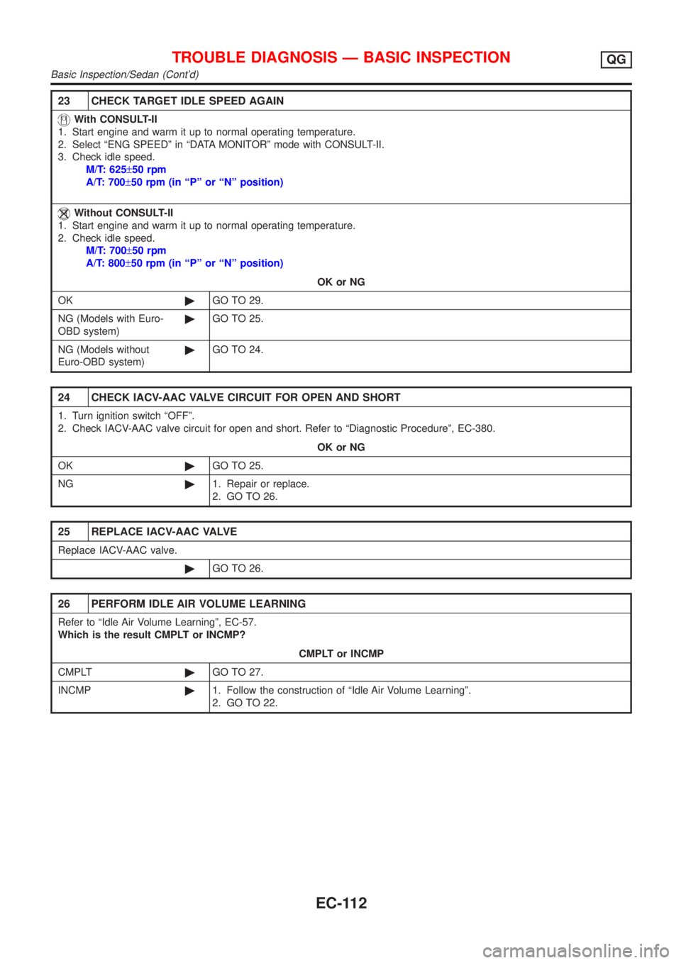
23 CHECK TARGET IDLE SPEED AGAIN
With CONSULT-II
1. Start engine and warm it up to normal operating temperature.
2. Select ªENG SPEEDº in ªDATA MONITORº mode with CONSULT-II.
3. Check idle speed.
M/T: 625±50 rpm
A/T: 700±50 rpm (in ªPº or ªNº position)
Without CONSULT-II
1. Start engine and warm it up to normal operating temperature.
2. Check idle speed.
M/T: 700±50 rpm
A/T: 800±50 rpm (in ªPº or ªNº position)
OK or NG
OK©GO TO 29.
NG (Models with Euro-
OBD system)©GO TO 25.
NG (Models without
Euro-OBD system)©GO TO 24.
24 CHECK IACV-AAC VALVE CIRCUIT FOR OPEN AND SHORT
1. Turn ignition switch ªOFFº.
2. Check IACV-AAC valve circuit for open and short. Refer to ªDiagnostic Procedureº, EC-380.
OK or NG
OK©GO TO 25.
NG©1. Repair or replace.
2. GO TO 26.
25 REPLACE IACV-AAC VALVE
Replace IACV-AAC valve.
©GO TO 26.
26 PERFORM IDLE AIR VOLUME LEARNING
Refer to ªIdle Air Volume Learningº, EC-57.
Which is the result CMPLT or INCMP?
CMPLT or INCMP
CMPLT©GO TO 27.
INCMP©1. Follow the construction of ªIdle Air Volume Learningº.
2. GO TO 22.
TROUBLE DIAGNOSIS Ð BASIC INSPECTIONQG
Basic Inspection/Sedan (Cont'd)
EC-112
Page 837 of 2898

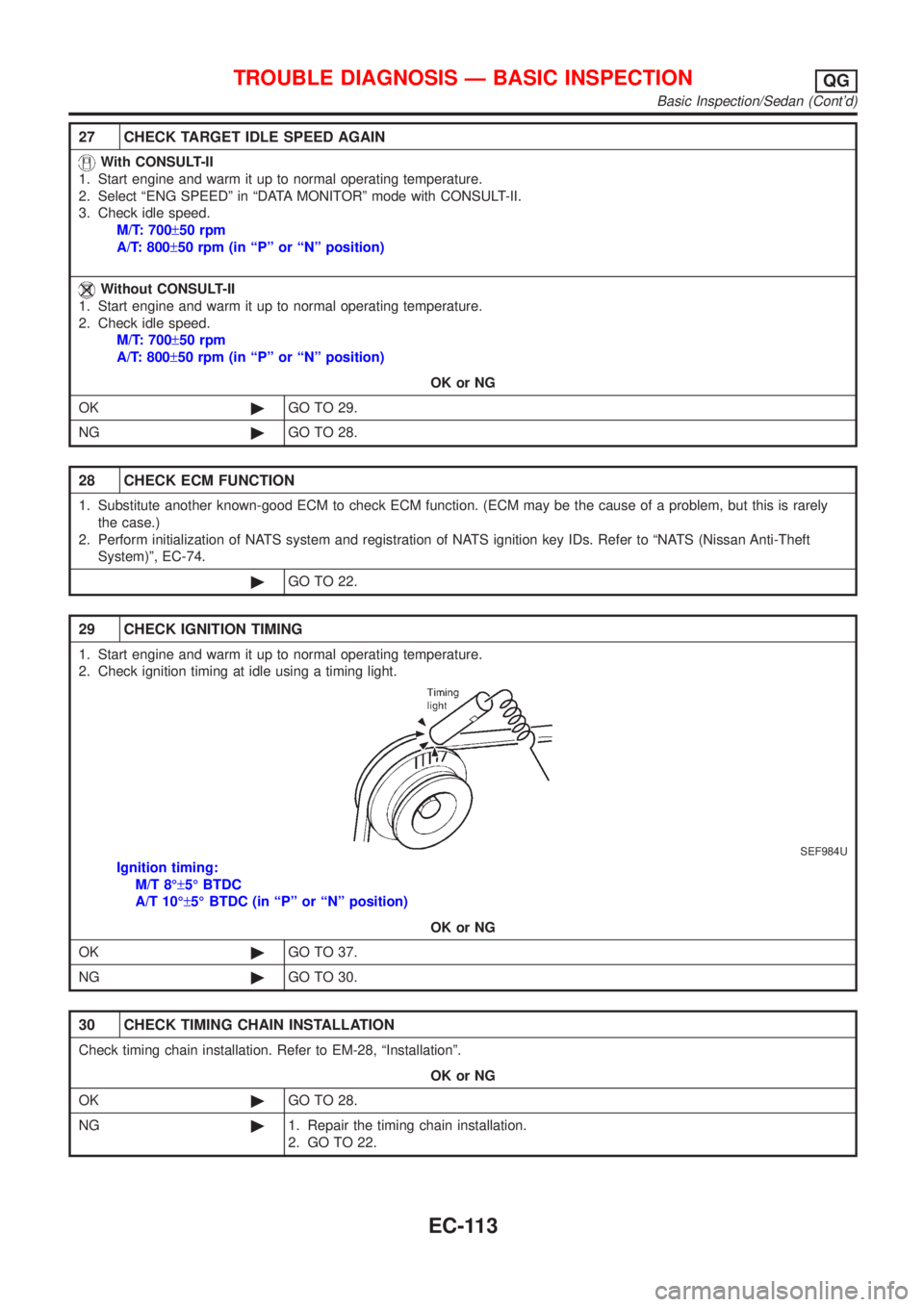
27 CHECK TARGET IDLE SPEED AGAIN
With CONSULT-II
1. Start engine and warm it up to normal operating temperature.
2. Select ªENG SPEEDº in ªDATA MONITORº mode with CONSULT-II.
3. Check idle speed.
M/T: 700±50 rpm
A/T: 800±50 rpm (in ªPº or ªNº position)
Without CONSULT-II
1. Start engine and warm it up to normal operating temperature.
2. Check idle speed.
M/T: 700±50 rpm
A/T: 800±50 rpm (in ªPº or ªNº position)
OK or NG
OK©GO TO 29.
NG©GO TO 28.
28 CHECK ECM FUNCTION
1. Substitute another known-good ECM to check ECM function. (ECM may be the cause of a problem, but this is rarely
the case.)
2. Perform initialization of NATS system and registration of NATS ignition key IDs. Refer to ªNATS (Nissan Anti-Theft
System)º, EC-74.
©GO TO 22.
29 CHECK IGNITION TIMING
1. Start engine and warm it up to normal operating temperature.
2. Check ignition timing at idle using a timing light.
SEF984U
Ignition timing:
M/T 8ɱ5É BTDC
A/T 10ɱ5É BTDC (in ªPº or ªNº position)
OK or NG
OK©GO TO 37.
NG©GO TO 30.
30 CHECK TIMING CHAIN INSTALLATION
Check timing chain installation. Refer to EM-28, ªInstallationº.
OK or NG
OK©GO TO 28.
NG©1. Repair the timing chain installation.
2. GO TO 22.
TROUBLE DIAGNOSIS Ð BASIC INSPECTIONQG
Basic Inspection/Sedan (Cont'd)
EC-113