2001 NISSAN ALMERA roof
[x] Cancel search: roofPage 685 of 2898
Trouble Diagnoses=NJBT0022DIAGNOSTIC TABLENJBT0022S01NOTE:
For diagnosing electric problem, refer to ªELECTRIC SUNROOFº
in EL section.
Check items (Components)
Wind deflector Adjustment Drain hoses WeatherstripLink and wire
assembly
Reference page BT-67 BT-68 BT-69 BT-69 BT-70
SymptomExcessive wind
noise12 3
Water leaks 1 2 3
Sunroof rattles1423
Excessive opera-
tion noise123
The numbers in this table mean checking order.
SBT331
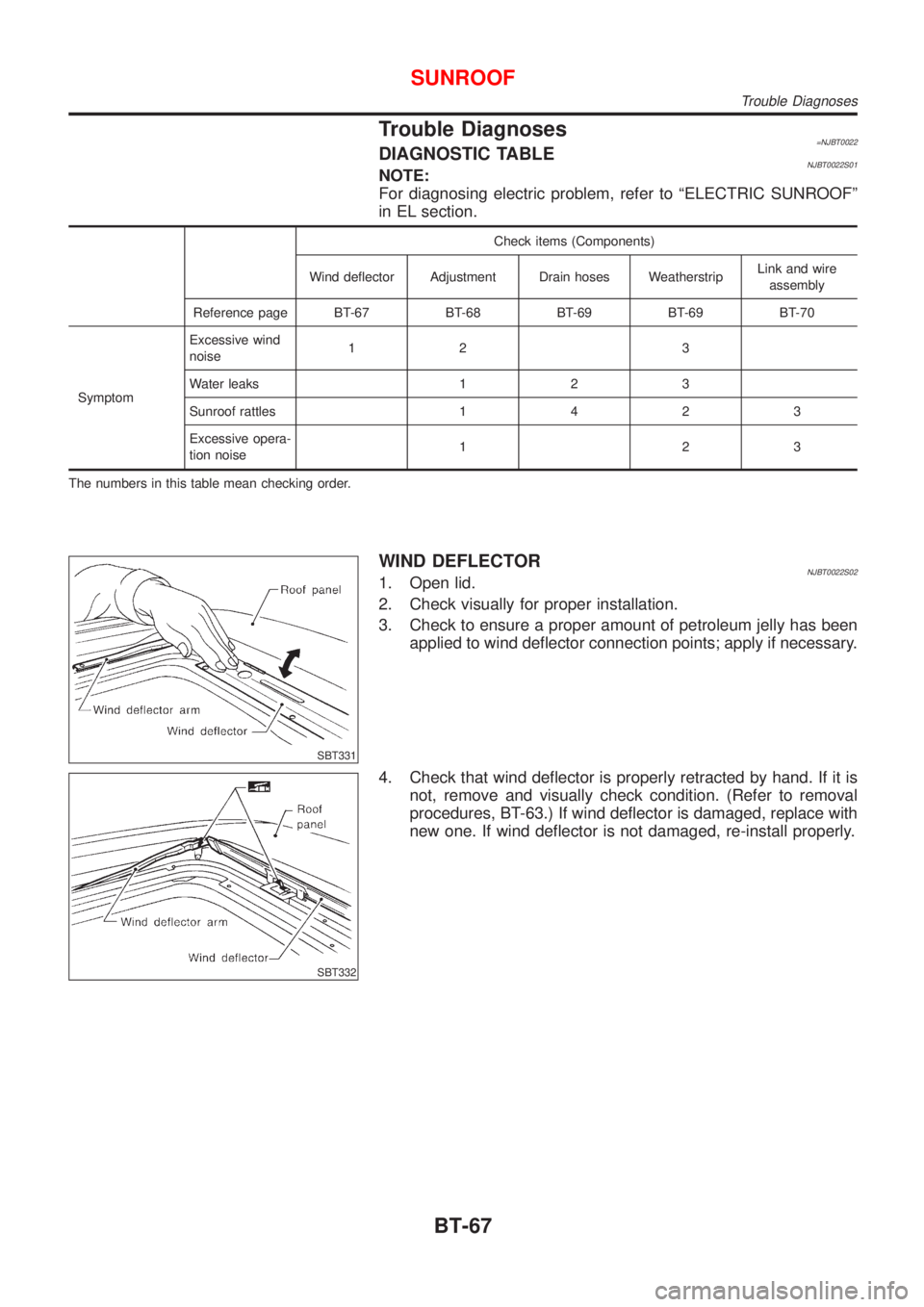
WIND DEFLECTORNJBT0022S021. Open lid.
2. Check visually for proper installation.
3. Check to ensure a proper amount of petroleum jelly has been
applied to wind deflector connection points; apply if necessary.
SBT332
4. Check that wind deflector is properly retracted by hand. If it is
not, remove and visually check condition. (Refer to removal
procedures, BT-63.) If wind deflector is damaged, replace with
new one. If wind deflector is not damaged, re-install properly.
SUNROOF
Trouble Diagnoses
BT-67
Page 686 of 2898
ADJUSTMENTNJBT0022S03
SBT004A
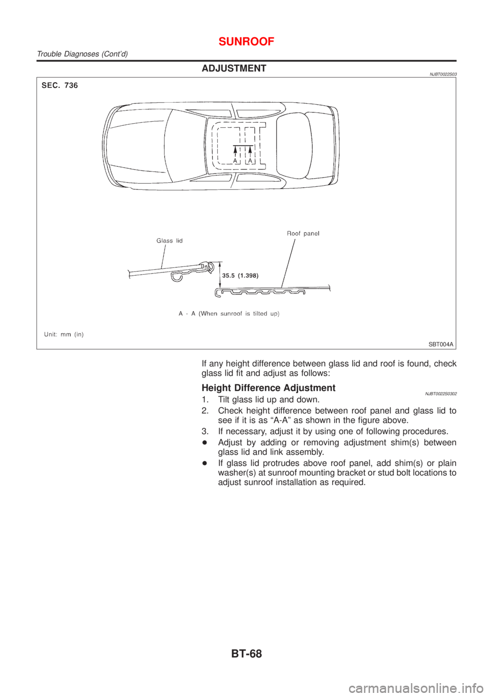
If any height difference between glass lid and roof is found, check
glass lid fit and adjust as follows:
Height Difference AdjustmentNJBT0022S03021. Tilt glass lid up and down.
2. Check height difference between roof panel and glass lid to
see if it is as ªA-Aº as shown in the figure above.
3. If necessary, adjust it by using one of following procedures.
+Adjust by adding or removing adjustment shim(s) between
glass lid and link assembly.
+If glass lid protrudes above roof panel, add shim(s) or plain
washer(s) at sunroof mounting bracket or stud bolt locations to
adjust sunroof installation as required.
SUNROOF
Trouble Diagnoses (Cont'd)
BT-68
Page 687 of 2898
DRAIN HOSESNJBT0022S04
SBT005A
SBT333
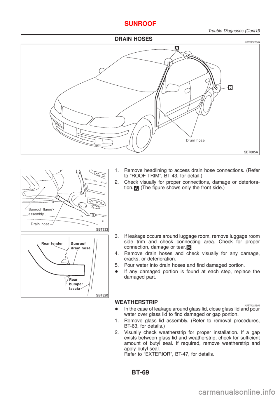
1. Remove headlining to access drain hose connections. (Refer
to ªROOF TRIMº, BT-43, for detail.)
2. Check visually for proper connections, damage or deteriora-
tion.
(The figure shows only the front side.)
SBT820
3. If leakage occurs around luggage room, remove luggage room
side trim and check connecting area. Check for proper
connection, damage or tear.
4. Remove drain hoses and check visually for any damage,
cracks, or deterioration.
5. Pour water into drain hoses and find damaged portion.
+If any damaged portion is found at each step, replace the
damaged part.
WEATHERSTRIPNJBT0022S05+In the case of leakage around glass lid, close glass lid and pour
water over glass lid to find damaged or gap portion.
1. Remove glass lid assembly. (Refer to removal procedures,
BT-63, for details.)
2. Visually check weatherstrip for proper installation. If a gap
exists between glass lid and weatherstrip, check for sufficient
amount of butyl seal. If required, remove weatherstrip and
apply butyl seal.
Refer to ªEXTERIORº, BT-47, for details.
SUNROOF
Trouble Diagnoses (Cont'd)
BT-69
Page 688 of 2898
3. Check weatherstrip visually for any damage, deterioration, or
flattening.
+If any damage is found, replace weatherstrip.
CAUTION:
Do not remove weatherstrip except when replacing, or filling
up butyl seal.
LINK AND WIRE ASSEMBLYNJBT0022S06NOTE:
Before replacing a suspect part, carefully ensure it is the source of
noise being experienced.
1. Check link to determine if coating film has peeled off to such
an extent that substrate is visible. Check also to determine if
link is the source of noise. If it is, replace it.
2. Visually check to determine if a sufficient amount of petroleum
jelly has been applied to wire or rail groove. If not, add petro-
leum jelly as required.
3. Check wire for any damage or deterioration. If any damage is
found, remove rear guide (refer to removal procedures, BT-63,
for details), then replace wire.
SUNROOF
Trouble Diagnoses (Cont'd)
BT-70
Page 1561 of 2898
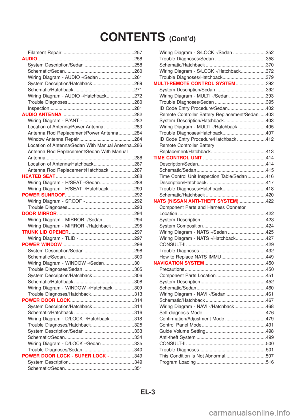
Filament Repair .......................................................257
AUDIO..........................................................................258
System Description/Sedan ......................................258
Schematic/Sedan .....................................................260
Wiring Diagram - AUDIO -/Sedan ...........................261
System Description/Hatchback ................................269
Schematic/Hatchback ..............................................271
Wiring Diagram - AUDIO -/Hatchback .....................272
Trouble Diagnoses...................................................280
Inspection.................................................................281
AUDIO ANTENNA.......................................................282
Wiring Diagram - P/ANT - .......................................282
Location of Antenna/Power Antenna .......................283
Antenna Rod Replacement/Power Antenna ............284
Window Antenna Repair ..........................................284
Location of Antenna/Sedan With Manual Antenna..286
Antenna Rod Replacement/Sedan With Manual
Antenna....................................................................286
Location of Antenna/Hatchback ...............................287
Antenna Rod Replacement/Hatchback ...................287
HEATED SEAT............................................................288
Wiring Diagram - H/SEAT -/Sedan ..........................288
Wiring Diagram - H/SEAT -/Hatchback ...................290
POWER SUNROOF.....................................................292
Wiring Diagram - SROOF - .....................................292
Trouble Diagnoses...................................................293
DOOR MIRROR...........................................................294
Wiring Diagram - MIRROR -/Sedan ........................294
Wiring Diagram - MIRROR -/Hatchback .................295
TRUNK LID OPENER..................................................297
Wiring Diagram - TLID - ..........................................297
POWER WINDOW.......................................................298
System Description/Sedan ......................................298
Schematic/Sedan .....................................................300
Wiring Diagram - WINDOW -/Sedan .......................301
Trouble Diagnoses/Sedan .......................................305
System Description/Hatchback ................................306
Schematic/Hatchback ..............................................308
Wiring Diagram - WINDOW -/Hatchback ................309
Trouble Diagnoses/Hatchback.................................313
POWER DOOR LOCK.................................................314
System Description/Hatchback ................................314
Schematic/Hatchback ..............................................316
Wiring Diagram - D/LOCK -/Hatchback...................318
Trouble Diagnoses/Hatchback.................................325
System Description/Sedan ......................................333
Schematic/Sedan .....................................................334
Wiring Diagram - D/LOCK -/Sedan .........................335
Trouble Diagnoses/Sedan .......................................340
POWER DOOR LOCK - SUPER LOCK -...................349
System Description ..................................................349
Schematic/Sedan .....................................................351Wiring Diagram - S/LOCK -/Sedan .........................352
Trouble Diagnoses/Sedan .......................................358
Schematic/Hatchback ..............................................370
Wiring Diagram - S/LOCK -/Hatchback ...................372
Trouble Diagnoses/Hatchback.................................379
MULTI-REMOTE CONTROL SYSTEM.......................392
System Description/Sedan ......................................392
Wiring Diagram - MULTI -/Sedan ............................393
Trouble Diagnoses/Sedan .......................................395
ID Code Entry Procedure/Sedan .............................402
Remote Controller Battery Replacement/Sedan .....403
System Description/Hatchback ................................403
Wiring Diagram - MULTI -/Hatchback .....................405
Trouble Diagnoses/Hatchback.................................407
ID Code Entry Procedure/Hatchback ......................412
Remote Controller Battery
Replacement/Hatchback ..........................................413
TIME CONTROL UNIT................................................414
Description/Sedan....................................................414
Schematic/Sedan .....................................................415
Time Control Unit Inspection Table/Sedan ..............416
Description/Hatchback .............................................417
Trouble Diagnoses/Hatchback.................................418
Schematic/Hatchback ..............................................420
NATS (NISSAN ANTI-THEFT SYSTEM).....................422
Component Parts and Harness Connetor
Location ...................................................................422
System Description ..................................................423
System Composition ................................................424
Wiring Diagram - NATS -/Sedan .............................425
Wiring Diagram - NATS -/Hatchback.......................427
CONSULT-II .............................................................429
Trouble Diagnoses...................................................432
How to Replace NATS IMMU ..................................449
NAVIGATION SYSTEM...............................................450
Precautions ..............................................................450
Component Parts Location ......................................451
System Description ..................................................452
Schematic/Sedan .....................................................460
Wiring Diagram - NAVI -/Sedan ..............................461
Schematic/Hatchback ..............................................467
Wiring Diagram - NAVI -/Hatchback ........................468
Self-diagnosis Mode ................................................476
Confirmation/Adjustment Mode ...............................479
Control Panel Mode .................................................491
Guide Volume Setting ..............................................498
Anti-theft System .....................................................499
CONSULT-II .............................................................500
Trouble Diagnoses...................................................501
This Condition Is Not Abnormal...............................507
Program Loading .....................................................516
CONTENTS(Cont'd)
EL-3
Page 1838 of 2898
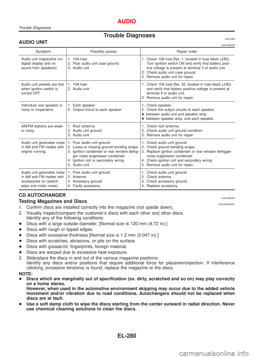
Trouble DiagnosesNJEL0385AUDIO UNITNJEL0385S05
Symptom Possible causes Repair order
Audio unit inoperative (no
digital display and no
sound from speakers).1. 10A fuse
2. Poor audio unit case ground
3. Audio unit1. Check 10A fuse [No. 1, located in fuse block (J/B)].
Turn ignition switch ON and verify that battery posi-
tive voltage is present at terminal 3 of audio unit.
2. Check audio unit case ground.
3. Remove audio unit for repair.
Audio unit presets are lost
when ignition switch is
turned OFF.1. 15A fuse
2. Audio unit1. Check 15A fuse [No. 32, located in fuse block (J/B)]
and verify that battery positive voltage is present at
terminal 9 of audio unit.
2. Remove audio unit for repair.
Individual rear speaker is
noisy or inoperative.1. Each speaker
2. Output circuit to each speaker1. Check speaker.
2. Check the output circuits to each speaker
+between audio unit and speaker amp.
+between speaker amp. and each speaker.
AM/FM stations are weak
or noisy.1. Roof antenna
2. Audio unit ground
3. Audio unit1. Check roof antenna.
2. Check audio unit ground condition.
3. Remove audio unit for repair.
Audio unit generates noise
in AM and FM modes with
engine running.1. Poor audio unit ground
2. Loose or missing ground bonding straps
3. Ignition condenser or rear window defog-
ger noise suppressor condenser
4. Ignition coil or secondary wiring
5. Audio unit1. Check audio unit ground.
2. Check ground bonding straps.
3. Replace ignition condenser or rear window defogger
noise suppressor condenser.
4. Check ignition coil and secondary wiring.
5. Remove audio unit for repair.
Audio unit generates noise
in AM and FM modes with
accessories on (switch
pops and motor noise).1. Poor audio unit ground
2. Antenna
3. Accessory ground
4. Faulty accessory1. Check audio unit ground.
2. Check antenna.
3. Check accessory ground.
4. Replace accessory.
CD AUTOCHANGERNJEL0385S06Testing Magazines and DiscsNJEL0385S06011. Confirm discs are installed correctly into the magazine (not upside down).
2. Visually inspect/compare the customer's discs with each other and other discs.
Identify any of the following conditions:
+Discs with a large outside diameter. [Normal size is 120 mm (4.72 in).]
+Discs with rough or lipped edges.
+Discs with excessive thickness [Normal size is 1.2 mm (0.047 in).]
+Discs with scratches, abrasions, or pits on the surface.
+Discs with grease/oil, fingerprints, foreign material.
+Discs are warped due to excessive heat exposure.
3. Slide/place the discs in and out of the various magazine positions.
Identify any discs and/or positions that require additional force for placement/ejection. If interference
(sticking, excessive tensions) is found, replace the magazine or the discs.
NOTE:
+Discs which are marginally out of specification (ex. dirty, scratched and so on) may play correctly
on a home stereo.
However, when used in the automotive environment skipping may occur due to the added vehicle
movement and/or vibration due to road conditions. Autochangers should not be replaced when
discs are at fault.
+Use a soft damp cloth to wipe the discs starting from the center outward in radial direction. Never
use chemical cleaning solutions to clean the discs.
AUDIO
Trouble Diagnoses
EL-280
Page 1850 of 2898
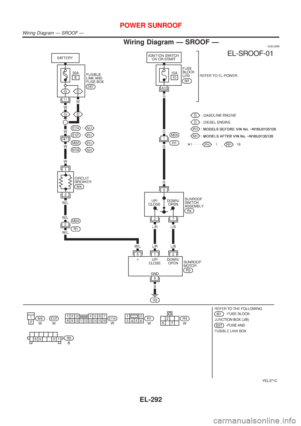
Wiring Diagram Ð SROOF ÐNJEL0089
YEL371C
POWER SUNROOF
Wiring Diagram Ð SROOF Ð
EL-292
Page 1851 of 2898
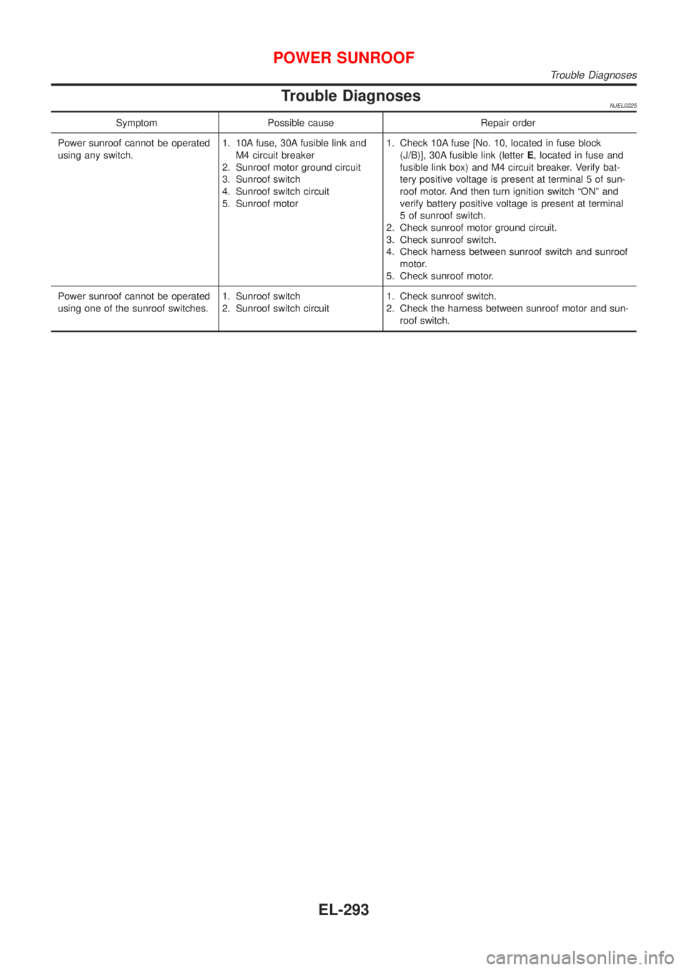
Trouble DiagnosesNJEL0225
Symptom Possible cause Repair order
Power sunroof cannot be operated
using any switch.1. 10A fuse, 30A fusible link and
M4 circuit breaker
2. Sunroof motor ground circuit
3. Sunroof switch
4. Sunroof switch circuit
5. Sunroof motor1. Check 10A fuse [No. 10, located in fuse block
(J/B)], 30A fusible link (letterE, located in fuse and
fusible link box) and M4 circuit breaker. Verify bat-
tery positive voltage is present at terminal 5 of sun-
roof motor. And then turn ignition switch ªONº and
verify battery positive voltage is present at terminal
5 of sunroof switch.
2. Check sunroof motor ground circuit.
3. Check sunroof switch.
4. Check harness between sunroof switch and sunroof
motor.
5. Check sunroof motor.
Power sunroof cannot be operated
using one of the sunroof switches.1. Sunroof switch
2. Sunroof switch circuit1. Check sunroof switch.
2. Check the harness between sunroof motor and sun-
roof switch.
POWER SUNROOF
Trouble Diagnoses
EL-293