2001 NISSAN ALMERA oil
[x] Cancel search: oilPage 39 of 2898

SAT015J
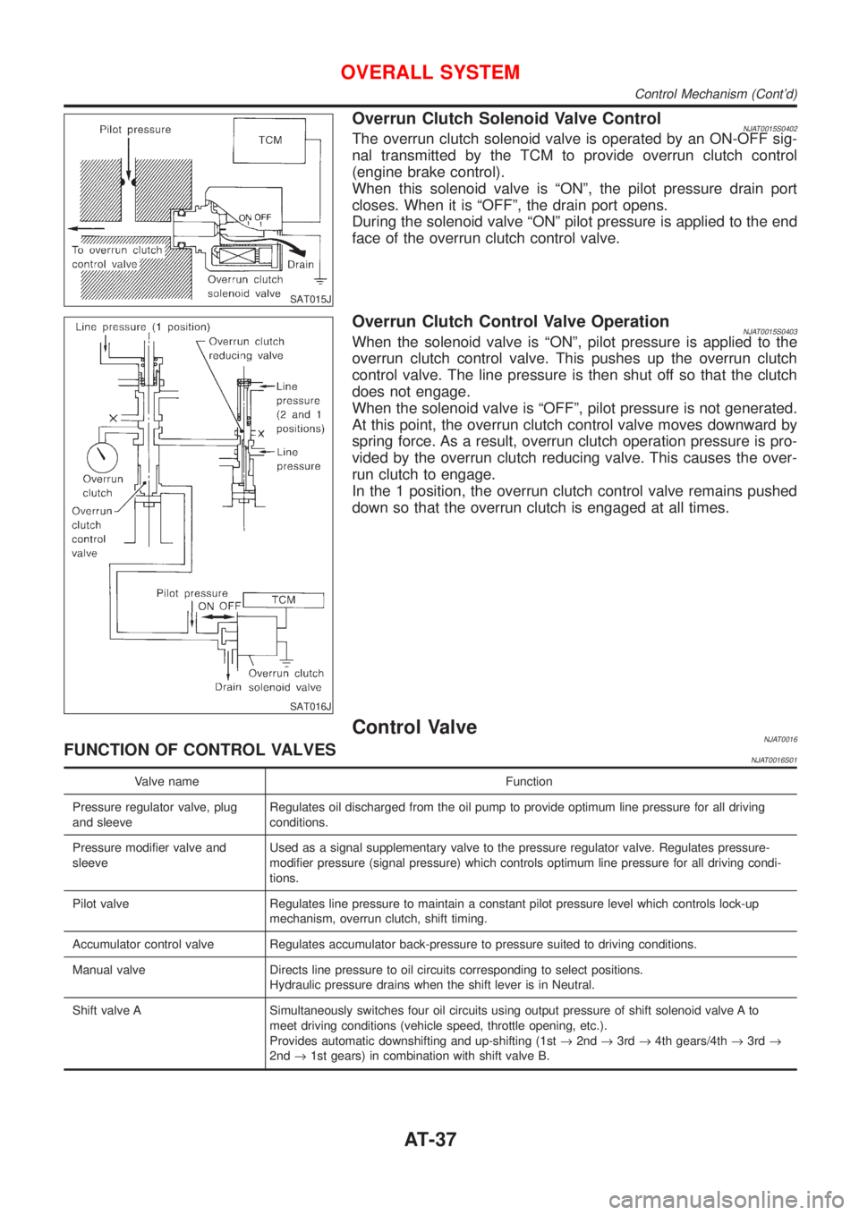
Overrun Clutch Solenoid Valve ControlNJAT0015S0402The overrun clutch solenoid valve is operated by an ON-OFF sig-
nal transmitted by the TCM to provide overrun clutch control
(engine brake control).
When this solenoid valve is ªONº, the pilot pressure drain port
closes. When it is ªOFFº, the drain port opens.
During the solenoid valve ªONº pilot pressure is applied to the end
face of the overrun clutch control valve.
SAT016J
Overrun Clutch Control Valve OperationNJAT0015S0403When the solenoid valve is ªONº, pilot pressure is applied to the
overrun clutch control valve. This pushes up the overrun clutch
control valve. The line pressure is then shut off so that the clutch
does not engage.
When the solenoid valve is ªOFFº, pilot pressure is not generated.
At this point, the overrun clutch control valve moves downward by
spring force. As a result, overrun clutch operation pressure is pro-
vided by the overrun clutch reducing valve. This causes the over-
run clutch to engage.
In the 1 position, the overrun clutch control valve remains pushed
down so that the overrun clutch is engaged at all times.
Control ValveNJAT0016FUNCTION OF CONTROL VALVESNJAT0016S01
Valve name Function
Pressure regulator valve, plug
and sleeveRegulates oil discharged from the oil pump to provide optimum line pressure for all driving
conditions.
Pressure modifier valve and
sleeveUsed as a signal supplementary valve to the pressure regulator valve. Regulates pressure-
modifier pressure (signal pressure) which controls optimum line pressure for all driving condi-
tions.
Pilot valve Regulates line pressure to maintain a constant pilot pressure level which controls lock-up
mechanism, overrun clutch, shift timing.
Accumulator control valve Regulates accumulator back-pressure to pressure suited to driving conditions.
Manual valve Directs line pressure to oil circuits corresponding to select positions.
Hydraulic pressure drains when the shift lever is in Neutral.
Shift valve A Simultaneously switches four oil circuits using output pressure of shift solenoid valve A to
meet driving conditions (vehicle speed, throttle opening, etc.).
Provides automatic downshifting and up-shifting (1st®2nd®3rd®4th gears/4th®3rd®
2nd®1st gears) in combination with shift valve B.
OVERALL SYSTEM
Control Mechanism (Cont'd)
AT-37
Page 40 of 2898

Valve name Function
Shift valve B Simultaneously switches three oil circuits using output pressure of shift solenoid valve B in
relation to driving conditions (vehicle speed, throttle opening, etc.).
Provides automatic downshifting and up-shifting (1st®2nd®3rd®4th gears/4th®3rd®
2nd®1st gears) in combination with shift valve A.
Overrun clutch control valve Switches hydraulic circuits to prevent engagement of the overrun clutch simultaneously with
application of the brake band in D
4. (Interlocking occurs if the overrun clutch engages during
D
4.)
1st reducing valve Reduces low & reverse brake pressure to dampen engine-brake shock when down-shifting
from the ª1º position 1
2to 11.
Overrun clutch reducing valve Reduces oil pressure directed to the overrun clutch and prevents engine-brake shock.
In ª1º and ª2º positions, line pressure acts on the overrun clutch reducing valve to increase
the pressure-regulating point, with resultant engine brake capability.
Torque converter relief valve Prevents an excessive rise in torque converter pressure.
Torque converter clutch control
valve, plug and sleeveActivates or inactivates the lock-up function.
Also provides smooth lock-up through transient application and release of the lock-up system.
1-2 accumulator valve and piston Dampens the shock encountered when 2nd gear band servo contracts, and provides smooth
shifting.
3-2 timing valve Switches oil pressure with 3-2 timing valve according to throttle opening.
Shuttle control valve Reduces shock when down-shifting from 3rd to 2nd and regulates overrun clutch.
Cooler check valve Regulates oil pressure which causes lock-up when driving at low speeds.
OVERALL SYSTEM
Control Valve (Cont'd)
AT-38
Page 82 of 2898

SAT767B
A/T Fluid CheckNJAT0025FLUID LEAKAGE CHECKNJAT0025S011. Clean area suspected of leaking. Ð for example, mating sur-
face of converter housing and transmission case.
2. Start engine, apply foot brake, place selector lever in ªDº posi-
tion and wait a few minutes.
3. Stop engine.
SAT288G
4. Check for fresh leakage.
SAT638A
FLUID CONDITION CHECKNJAT0025S02
Fluid color Suspected problem
Dark or black with burned odor Wear of frictional material
Milky pink Water contamination Ð Road water
entering through filler tube or breather
Varnished fluid, light to dark brown
and tackyOxidation Ð Over or under filling, Ð
Overheating
FLUID LEVEL CHECKNJAT0025S03Refer to ªChecking A/T Fluidº, AT-15.
SAT647B
Stall TestNJAT0026STALL TEST PROCEDURENJAT0026S011. Check A/T fluid and engine oil levels. If necessary, add.
2. Drive vehicle for approx. 10 minutes or until fluid and oil reach
operating temperature.
ATF operating temperature:
50 - 80ÉC (122 - 176ÉF)
TROUBLE DIAGNOSIS Ð BASIC INSPECTION
A/T Fluid Check
AT-80
Page 86 of 2898

SAT561J
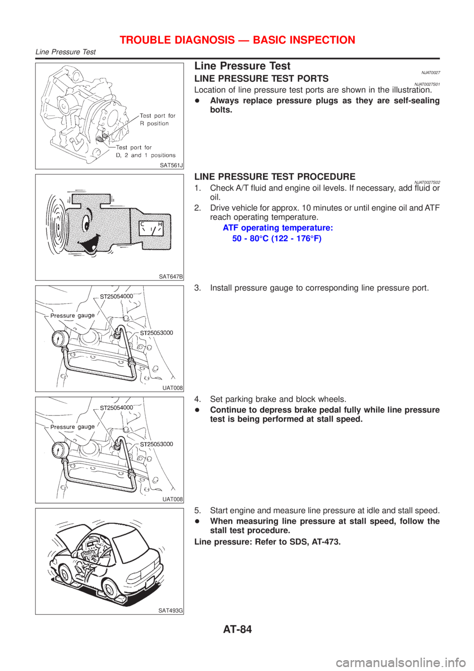
Line Pressure TestNJAT0027LINE PRESSURE TEST PORTSNJAT0027S01Location of line pressure test ports are shown in the illustration.
+Always replace pressure plugs as they are self-sealing
bolts.
SAT647B
LINE PRESSURE TEST PROCEDURENJAT0027S021. Check A/T fluid and engine oil levels. If necessary, add fluid or
oil.
2. Drive vehicle for approx. 10 minutes or until engine oil and ATF
reach operating temperature.
ATF operating temperature:
50 - 80ÉC (122 - 176ÉF)
UAT008
3. Install pressure gauge to corresponding line pressure port.
UAT008
4. Set parking brake and block wheels.
+Continue to depress brake pedal fully while line pressure
test is being performed at stall speed.
SAT493G
5. Start engine and measure line pressure at idle and stall speed.
+When measuring line pressure at stall speed, follow the
stall test procedure.
Line pressure: Refer to SDS, AT-473.
TROUBLE DIAGNOSIS Ð BASIC INSPECTION
Line Pressure Test
AT-84
Page 87 of 2898

JUDGEMENT OF LINE PRESSURE TESTNJAT0027S03
Judgement Suspected parts
At idleLine pressure is low in all positions.+Oil pump wear
+Control piston damage
+Pressure regulator valve or plug sticking
+Spring for pressure regulator valve damaged
+Fluid pressure leakage between oil strainer and pressure regulator valve
+Clogged strainer
Line pressure is low in particular
position.+Fluid pressure leakage between manual valve and particular clutch
+For example, line pressure is:
þ Low in ªRº and ª1º positions, but
þ Normal in ªDº and ª2º positions.
Therefore, fluid leakage exists at or around low and reverse brake circuit.
Refer to ªCLUTCH AND BAND CHARTº, AT-23.
Line pressure is high.+Maladjustment of throttle position sensor
+A/T fluid temperature sensor damaged
+Line pressure solenoid valve sticking
+Short circuit of line pressure solenoid valve circuit
+Pressure modifier valve sticking
+Pressure regulator valve or plug sticking
+Open in dropping resistor circuit
At stall
speedLine pressure is low.+Maladjustment of throttle position sensor
+Line pressure solenoid valve sticking
+Short circuit of line pressure solenoid valve circuit
+Pressure regulator valve or plug sticking
+Pressure modifier valve sticking
+Pilot valve sticking
SAT786A
Road TestNJAT0028DESCRIPTIONNJAT0028S01+The purpose of the test is to determine overall performance of
A/T and analyze causes of problems.
+The road test consists of the following three parts:
1. Check before engine is started
2. Check at idle
3. Cruise test
SAT496G
+Before road test, familiarize yourself with all test procedures
and items to check.
+Conduct tests on all items until specified symptom is found.
Troubleshoot items which check out No Good after road test.
Refer to the following items.
ON BOARD DIAGNOSITC
SYSTEM DESCRIPTIONTROUBLE DIAGNOSES FOR
SYMPTOMS
General and
Except for
Euro-OBDAT-39 - AT-49 AT-290 and AT-296 - AT-334
TROUBLE DIAGNOSIS Ð BASIC INSPECTION
Line Pressure Test (Cont'd)
AT-85
Page 97 of 2898

Cruise Test Ð Part 1=NJAT0028S0404
1 CHECK STARTING GEAR (D1) POSITION
1. Drive vehicle for approx. 10 minutes to warm engine oil and ATF up to operating temperature.
ATF operating temperature:
50 - 80ÉC (122 - 176ÉF)
2. Park vehicle on flat surface.
3. Set overdrive control switch to ªONº position.
4. Move selector lever to ªPº position.
SAT774B
5. Start engine.
6. Move selector lever to ªDº position.
SAT775B
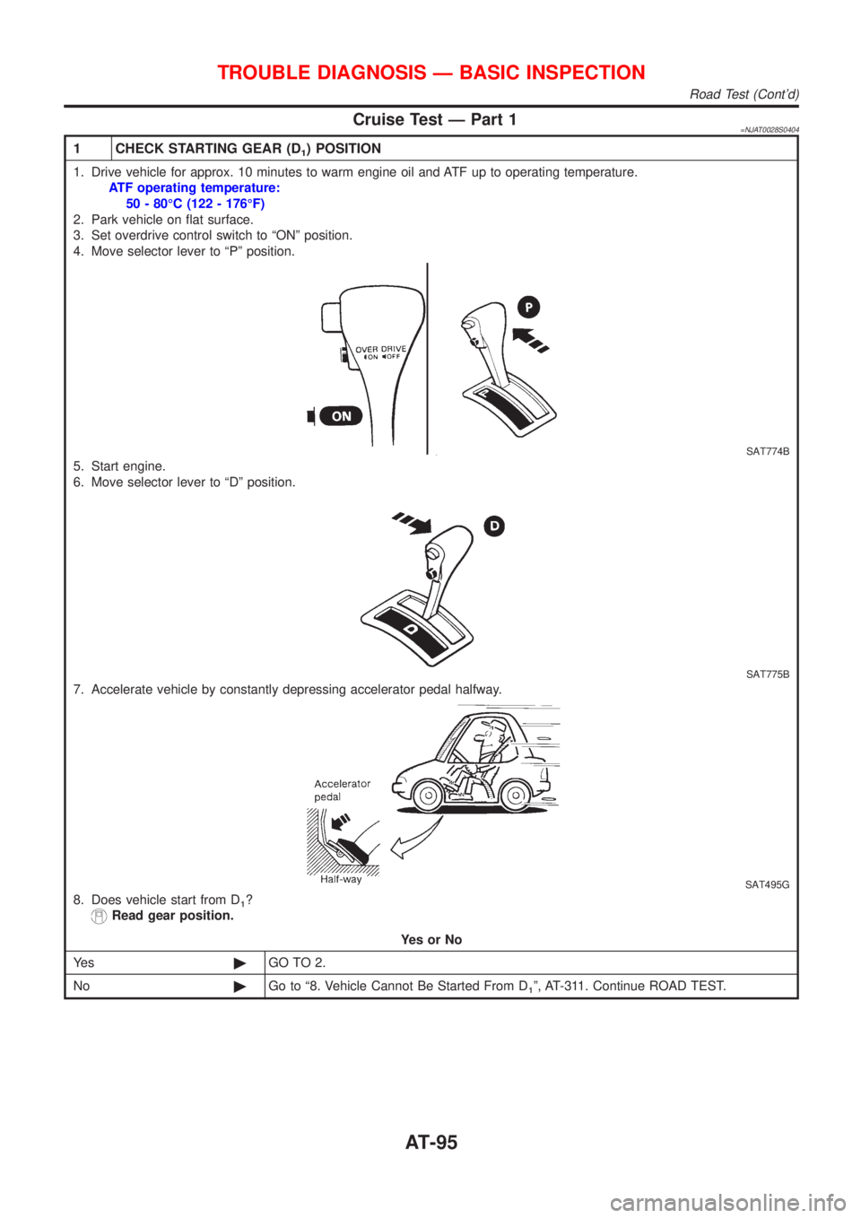
7. Accelerate vehicle by constantly depressing accelerator pedal halfway.
SAT495G
8. Does vehicle start from D1?
Read gear position.
YesorNo
Ye s©GO TO 2.
No©Go to ª8. Vehicle Cannot Be Started From D
1º, AT-311. Continue ROAD TEST.
TROUBLE DIAGNOSIS Ð BASIC INSPECTION
Road Test (Cont'd)
AT-95
Page 107 of 2898

Symptom ChartNJAT0029Numbers are arranged in order of inspection.
Perform inspections starting with number one and work up.
Symptom Condition Diagnostic ItemReference Page
General and
except for
Euro-OBDEURO-OBD
Engine cannot start in ªPº and ªNº
positions.
AT-299ON vehicle1. Ignition switch and starterEL-10, ªPOWER SUPPLY
ROUTINGº and SC-13,
ªSTARTING SYSTEMº
2. Control cable adjustment AT-352¬
3. PNP switch adjustment AT-352¬
Engine starts in position other than
ªNº and ªPº positions.
AT-299ON vehicle1. Control cable adjustment AT-352¬
2. PNP switch adjustment AT-352¬
Transaxle noise in ªPº and ªNº
positions.ON vehicle1. Fluid level AT-80¬
2. Line pressure test AT-84¬
3. Throttle position sensor (Adjustment)EC-207,
ªDTC P0120
THROTTLE
POSITION
SENSORºEC-207,
ªDTC P0120
THROTTLE
POSITION
SENSORº
4. Vehicle speed sensor´A/T (Revolution
sensor) and vehicle speed sensor´MTRAT-126,
AT-131AT-195,
AT-281
5. Engine speed signal AT-172 AT-200
OFF vehicle6. Oil pump AT-384¬
7. Torque converter AT-366¬
Vehicle moves when changing into
ªPº position, or parking gear does
not disengage when shifted out of
ªPº position.
AT-300ON vehicle 1. Control cable adjustment AT-352¬
OFF vehicle 2. Parking componentsAT-361,
AT-362AT-362
Vehicle runs in ªNº position.
AT-301ON vehicle 1. Control cable adjustment AT-352¬
OFF vehicle2. Forward clutch AT-412¬
3. Reverse clutch AT-403¬
4. Overrun clutch AT-412¬
Vehicle will not run in ªRº position
(but runs in ªDº, ª2º and ª1º posi-
tions). Clutch slips.
Very poor acceleration.
AT-305ON vehicle1. Control cable adjustment AT-352¬
2. Line pressure test AT-84¬
3. Line pressure solenoid valve AT-176 AT-239
4. Control valve assembly AT-351¬
OFF vehicle5. Reverse clutch AT-403¬
6. High clutch AT-407¬
7. Forward clutch AT-412¬
8. Overrun clutch AT-412¬
9. Low & reverse brake AT-419¬
TROUBLE DIAGNOSIS Ð GENERAL DESCRIPTION
Symptom Chart
AT-105
Page 109 of 2898

Symptom Condition Diagnostic ItemReference Page
General and
except for
Euro-OBDEURO-OBD
Clutches or brakes slip somewhat
in starting.ON vehicle1. Fluid level AT-80¬
2. Control cable adjustment AT-352¬
3. Throttle position sensor (Adjustment)EC-207,
ªDTC P0120
THROTTLE
POSITION
SENSORºEC-207,
ªDTC P0120
THROTTLE
POSITION
SENSORº
4. Line pressure test AT-84¬
5. Line pressure solenoid valve AT-176 AT-239
6. Control valve assembly AT-351¬
7. Accumulator N-D AT-351¬
OFF vehicle8. Forward clutch AT-412¬
9. Reverse clutch AT-403¬
10. Low & reverse brake AT-419¬
11. Oil pump AT-384¬
12. Torque converter AT-366¬
Excessive creep. ON vehicle 1. Engine idling rpmEC-43, ªIdle
Speed and
Ignition Tim-
ingºEC-43, ªIdle
Speed and
Ignition Tim-
ingº
No creep at all.
AT-305 and AT-308ON vehicle1. Fluid level AT-80¬
2. Line pressure test AT-84¬
3. Control valve assembly AT-351¬
OFF vehicle4. Forward clutch AT-412¬
5. Oil pump AT-384¬
6. Torque converter AT-366¬
Failure to change gear from ªD
1º
to ªD
2º.ON vehicle1. PNP switch adjustment AT-352¬
2. Control cable adjustment AT-352¬
3. Shift solenoid valve A AT-142 AT-246
4. Control valve assembly AT-351¬
5. Vehicle speed sensor´A/T (Revolution
sensor) and vehicle speed sensor´MTRAT-126,
AT-131AT-195,
AT-281
OFF vehicle 6. Brake band AT-437¬
TROUBLE DIAGNOSIS Ð GENERAL DESCRIPTION
Symptom Chart (Cont'd)
AT-107