2001 NISSAN ALMERA oil pressure
[x] Cancel search: oil pressurePage 2276 of 2898
JEM193G
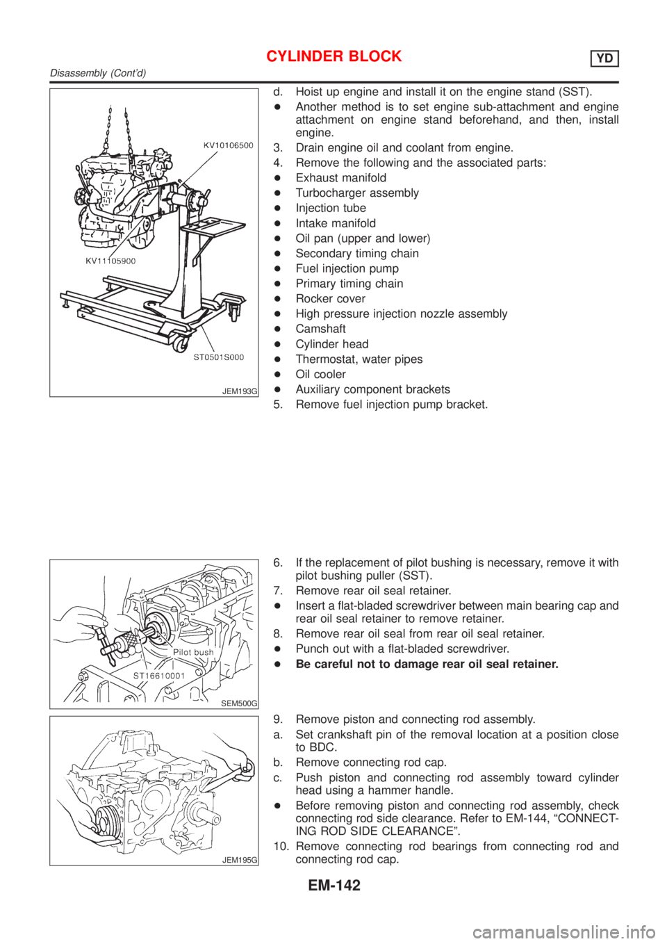
d. Hoist up engine and install it on the engine stand (SST).
+Another method is to set engine sub-attachment and engine
attachment on engine stand beforehand, and then, install
engine.
3. Drain engine oil and coolant from engine.
4. Remove the following and the associated parts:
+Exhaust manifold
+Turbocharger assembly
+Injection tube
+Intake manifold
+Oil pan (upper and lower)
+Secondary timing chain
+Fuel injection pump
+Primary timing chain
+Rocker cover
+High pressure injection nozzle assembly
+Camshaft
+Cylinder head
+Thermostat, water pipes
+Oil cooler
+Auxiliary component brackets
5. Remove fuel injection pump bracket.
SEM500G
6. If the replacement of pilot bushing is necessary, remove it with
pilot bushing puller (SST).
7. Remove rear oil seal retainer.
+Insert a flat-bladed screwdriver between main bearing cap and
rear oil seal retainer to remove retainer.
8. Remove rear oil seal from rear oil seal retainer.
+Punch out with a flat-bladed screwdriver.
+Be careful not to damage rear oil seal retainer.
JEM195G
9. Remove piston and connecting rod assembly.
a. Set crankshaft pin of the removal location at a position close
to BDC.
b. Remove connecting rod cap.
c. Push piston and connecting rod assembly toward cylinder
head using a hammer handle.
+Before removing piston and connecting rod assembly, check
connecting rod side clearance. Refer to EM-144, ªCONNECT-
ING ROD SIDE CLEARANCEº.
10. Remove connecting rod bearings from connecting rod and
connecting rod cap.
CYLINDER BLOCKYD
Disassembly (Cont'd)
EM-142
Page 2294 of 2898
General SpecificationsNJEM0075
Cylinder arrangementIn-line 4
Displacement cm
3(cu in)2,184 (133.27)
Bore and stroke mm (in)86 x 94 (3.39 x 3.70)
Valve arrangementDOHC
Firing order1-3-4-2
Number of piston ringsCompression 2
Oil 1
Number of main bearings5
Compression ratio18.0
Compression PressureNJEM0076Unit: kPa (bar, kg/cm2, psi)/200 rpm
Compression pressureStandard 3,138 (31.4, 32.0, 455)
Minimum 2,452 (24.5, 25.0, 356)
Differential limit between cylinders 490 (4.9, 5.0, 71)
Belt DeflectionNJEM0111
Applied belt Belt specificationBelt deflection with 98 N (10 kg, 22 lb) force applied*
mm (in)
New AdjustedLimit for re-tighten-
ing
Air conditioner compressor belt HA type low edge belt4-5
(0.16 - 0.20)6-7
(0.24 - 0.28)8.5 (0.335)
Alternator & water pump beltHA type low-edge wide angle
belt9.0 - 10.5
(0.354 - 0.413)11.0 - 12.5
(0.433 - 0.492)16.5 (0.650)
*: When engine is cold.
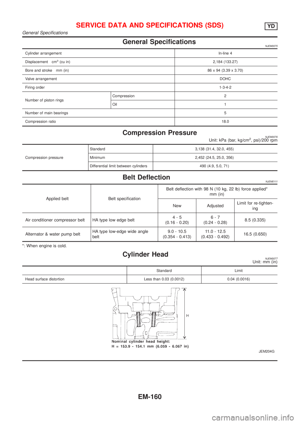
Cylinder HeadNJEM0077Unit: mm (in)
Standard Limit
Head surface distortion Less than 0.03 (0.0012) 0.04 (0.0016)
JEM204G
SERVICE DATA AND SPECIFICATIONS (SDS)YD
General Specifications
EM-160
Page 2406 of 2898
Precautions for Service EquipmentNJHA0117RECOVERY/RECYCLING EQUIPMENTNJHA0117S01Follow the manufacturer's instructions for machine operation and
machine maintenance. Never introduce any refrigerant other than
that specified into the machine.
ELECTRONIC LEAK DETECTORNJHA0117S02Follow the manufacture's instructions for tester operation and
tester maintenance.
RHA270D
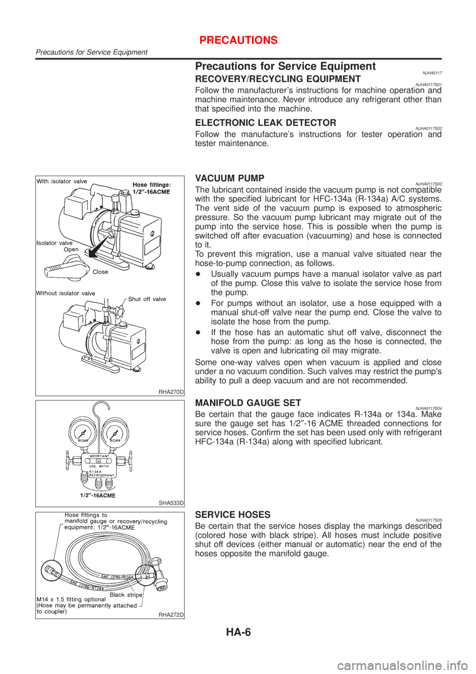
VACUUM PUMPNJHA0117S03The lubricant contained inside the vacuum pump is not compatible
with the specified lubricant for HFC-134a (R-134a) A/C systems.
The vent side of the vacuum pump is exposed to atmospheric
pressure. So the vacuum pump lubricant may migrate out of the
pump into the service hose. This is possible when the pump is
switched off after evacuation (vacuuming) and hose is connected
to it.
To prevent this migration, use a manual valve situated near the
hose-to-pump connection, as follows.
+Usually vacuum pumps have a manual isolator valve as part
of the pump. Close this valve to isolate the service hose from
the pump.
+For pumps without an isolator, use a hose equipped with a
manual shut-off valve near the pump end. Close the valve to
isolate the hose from the pump.
+If the hose has an automatic shut off valve, disconnect the
hose from the pump: as long as the hose is connected, the
valve is open and lubricating oil may migrate.
Some one-way valves open when vacuum is applied and close
under a no vacuum condition. Such valves may restrict the pump's
ability to pull a deep vacuum and are not recommended.
SHA533D
MANIFOLD GAUGE SETNJHA0117S04Be certain that the gauge face indicates R-134a or 134a. Make
sure the gauge set has 1/2²-16 ACME threaded connections for
service hoses. Confirm the set has been used only with refrigerant
HFC-134a (R-134a) along with specified lubricant.
RHA272D
SERVICE HOSESNJHA0117S05Be certain that the service hoses display the markings described
(colored hose with black stripe). All hoses must include positive
shut off devices (either manual or automatic) near the end of the
hoses opposite the manifold gauge.
PRECAUTIONS
Precautions for Service Equipment
HA-6
Page 2413 of 2898
Refrigeration System
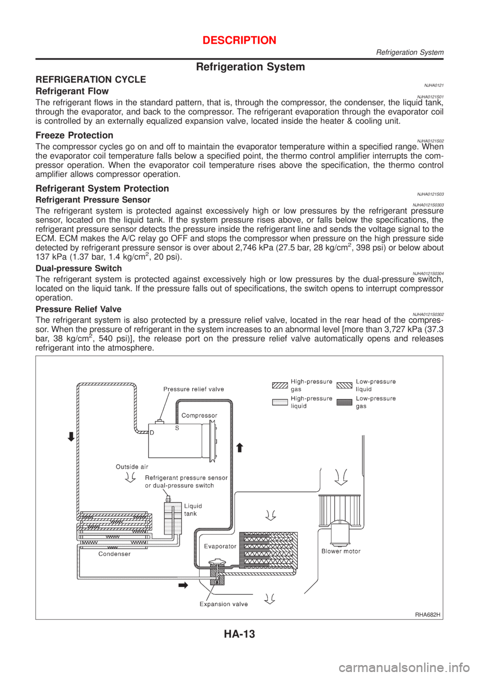
REFRIGERATION CYCLENJHA0121Refrigerant FlowNJHA0121S01The refrigerant flows in the standard pattern, that is, through the compressor, the condenser, the liquid tank,
through the evaporator, and back to the compressor. The refrigerant evaporation through the evaporator coil
is controlled by an externally equalized expansion valve, located inside the heater & cooling unit.
Freeze ProtectionNJHA0121S02The compressor cycles go on and off to maintain the evaporator temperature within a specified range. When
the evaporator coil temperature falls below a specified point, the thermo control amplifier interrupts the com-
pressor operation. When the evaporator coil temperature rises above the specification, the thermo control
amplifier allows compressor operation.
Refrigerant System ProtectionNJHA0121S03Refrigerant Pressure SensorNJHA0121S0303The refrigerant system is protected against excessively high or low pressures by the refrigerant pressure
sensor, located on the liquid tank. If the system pressure rises above, or falls below the specifications, the
refrigerant pressure sensor detects the pressure inside the refrigerant line and sends the voltage signal to the
ECM. ECM makes the A/C relay go OFF and stops the compressor when pressure on the high pressure side
detected by refrigerant pressure sensor is over about 2,746 kPa (27.5 bar, 28 kg/cm
2, 398 psi) or below about
137 kPa (1.37 bar, 1.4 kg/cm2, 20 psi).
Dual-pressure Switch
NJHA0121S0304The refrigerant system is protected against excessively high or low pressures by the dual-pressure switch,
located on the liquid tank. If the pressure falls out of specifications, the switch opens to interrupt compressor
operation.
Pressure Relief Valve
NJHA0121S0302The refrigerant system is also protected by a pressure relief valve, located in the rear head of the compres-
sor. When the pressure of refrigerant in the system increases to an abnormal level [more than 3,727 kPa (37.3
bar, 38 kg/cm
2, 540 psi)], the release port on the pressure relief valve automatically opens and releases
refrigerant into the atmosphere.
RHA682H
DESCRIPTION
Refrigeration System
HA-13
Page 2501 of 2898
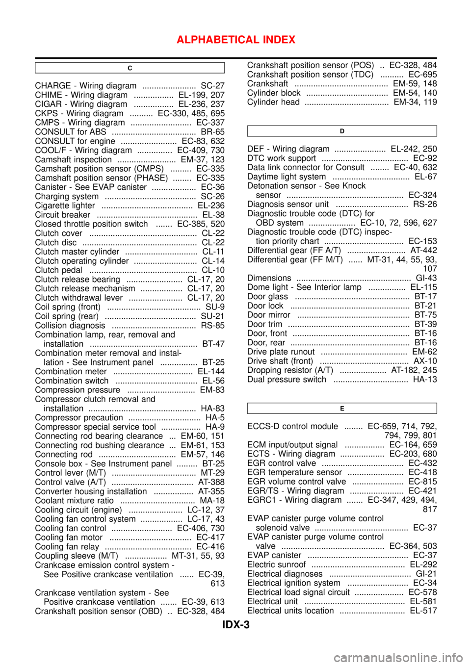
C
CHARGE - Wiring diagram ....................... SC-27
CHIME - Wiring diagram ................. EL-199, 207
CIGAR - Wiring diagram ................. EL-236, 237
CKPS - Wiring diagram .......... EC-330, 485, 695
CMPS - Wiring diagram .......................... EC-337
CONSULT for ABS .................................... BR-65
CONSULT for engine ........................ EC-83, 632
COOL/F - Wiring diagram ............... EC-409, 730
Camshaft inspection ......................... EM-37, 123
Camshaft position sensor (CMPS) ......... EC-335
Camshaft position sensor (PHASE) ........ EC-335
Canister - See EVAP canister ................... EC-36
Charging system ....................................... SC-26
Cigarette lighter ....................................... EL-236
Circuit breaker ........................................... EL-38
Closed throttle position switch ....... EC-385, 520
Clutch cover .............................................. CL-22
Clutch disc ................................................. CL-22
Clutch master cylinder ............................... CL-11
Clutch operating cylinder ........................... CL-14
Clutch pedal .............................................. CL-10
Clutch release bearing ........................ CL-17, 20
Clutch release mechanism .................. CL-17, 20
Clutch withdrawal lever ....................... CL-17, 20
Coil spring (front) ........................................ SU-9
Coil spring (rear) ....................................... SU-21
Collision diagnosis .................................... RS-85
Combination lamp, rear, removal and
installation .............................................. BT-47
Combination meter removal and instal-
lation - See Instrument panel ................ BT-25
Combination meter .................................. EL-144
Combination switch ................................... EL-56
Compression pressure ............................. EM-83
Compressor clutch removal and
installation .............................................. HA-83
Compressor precaution ............................... HA-5
Compressor special service tool ................. HA-9
Connecting rod bearing clearance ... EM-60, 151
Connecting rod bushing clearance ... EM-61, 153
Connecting rod ................................. EM-57, 146
Console box - See Instrument panel ......... BT-25
Control lever (M/T) .................................... MT-29
Control valve (A/T) ................................... AT-388
Converter housing installation ................. AT-355
Coolant mixture ratio ................................ MA-18
Cooling circuit (engine) ....................... LC-12, 37
Cooling fan control system .................. LC-17, 43
Cooling fan control .......................... EC-406, 730
Cooling fan motor ................................... EC-417
Cooling fan relay ..................................... EC-416
Coupling sleeve (M/T) .................. MT-31, 55, 93
Crankcase emission control system -
See Positive crankcase ventilation ...... EC-39,
613
Crankcase ventilation system - See
Positive crankcase ventilation ....... EC-39, 613
Crankshaft position sensor (OBD) .. EC-328, 484Crankshaft position sensor (POS) .. EC-328, 484
Crankshaft position sensor (TDC) .......... EC-695
Crankshaft ........................................ EM-59, 148
Cylinder block ................................... EM-54, 140
Cylinder head .................................... EM-34, 119
D
DEF - Wiring diagram ...................... EL-242, 250
DTC work support ..................................... EC-92
Data link connector for Consult ........ EC-40, 632
Daytime light system ................................. EL-67
Detonation sensor - See Knock
sensor .................................................. EC-324
Diagnosis sensor unit ............................... RS-26
Diagnostic trouble code (DTC) for
OBD system .................... EC-10, 72, 596, 627
Diagnostic trouble code (DTC) inspec-
tion priority chart .................................. EC-153
Differential gear (FF A/T) ......................... AT-442
Differential gear (FF M/T) ...... MT-31, 44, 55, 93,
107
Dimensions ................................................. GI-43
Dome light - See Interior lamp ................ EL-115
Door glass ................................................. BT-17
Door lock ................................................... BT-21
Door mirror ................................................ BT-75
Door trim .................................................... BT-39
Door, front .................................................. BT-16
Door, rear ................................................... BT-16
Drive plate runout ..................................... EM-62
Drive shaft (front) ...................................... AX-10
Dropping resistor (A/T) .................... AT-182, 245
Dual pressure switch ................................ HA-13
E
ECCS-D control module ........ EC-659, 714, 792,
794, 799, 801
ECM input/output signal ................. EC-164, 659
ECTS - Wiring diagram ................... EC-203, 680
EGR control valve ................................... EC-432
EGR temperature sensor ........................ EC-418
EGR volume control valve ...................... EC-815
EGR/TS - Wiring diagram ....................... EC-421
EGRC1 - Wiring diagram ....... EC-347, 429, 494,
817
EVAP canister purge volume control
solenoid valve ........................................ EC-37
EVAP canister purge volume control
valve ............................................ EC-364, 503
EVAP canister ........................................... EC-37
Electric sunroof ........................................ EL-292
Electrical diagnoses ................................... GI-21
Electrical ignition system .......................... EC-34
Electrical load signal circuit ..................... EC-578
Electrical unit ........................................... EL-581
Electrical units location ............................ EL-517
ALPHABETICAL INDEX
IDX-3
Page 2502 of 2898
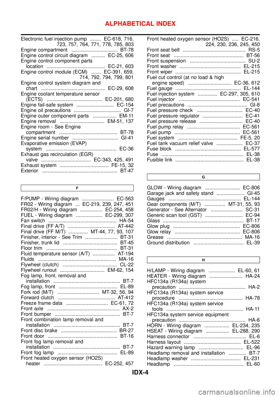
Electronic fuel injection pump ........ EC-618, 716,
723, 757, 764, 771, 778, 785, 803
Engine compartment ................................. BT-78
Engine control circuit diagram .......... EC-25, 606
Engine control component parts
location .......................................... EC-21, 603
Engine control module (ECM) ....... EC-391, 659,
714, 792, 794, 799, 801
Engine control system diagram and
chart .............................................. EC-29, 608
Engine coolant temperature sensor
(ECTS) ........................................ EC-201, 680
Engine fail-safe system ........................... EC-154
Engine oil precautions .................................. GI-7
Engine outer component parts ................. EM-11
Engine removal ................................ EM-51, 137
Engine room - See Engine
compartment .......................................... BT-78
Engine serial number ................................. GI-41
Evaporative emission (EVAP)
system ................................................... EC-36
Exhaust gas recirculation (EGR)
valve .................................... EC-343, 425, 491
Exhaust system ................................... FE-15, 32
Exterior ...................................................... BT-47
F
F/PUMP - Wiring diagram ....................... EC-563
FR02 - Wiring diagram ... EC-219, 239, 247, 451
FR02/H - Wiring diagram ................ EC-254, 458
FUEL - Wiring diagram ................... EC-299, 307
Fan switch ................................................. HA-54
Final drive (FF A/T) .................................. AT-442
Final drive (FF M/T) .............. MT-44, 77, 93, 107
Finisher, interior - See Trim ....................... BT-31
Finisher, trunk lid ....................................... BT-45
Floor trim ................................................... BT-31
Fluid temperature sensor (A/T) ................ AT-194
Fluids ........................................................ MA-16
Flywheel (clutch) ....................................... CL-22
Flywheel runout ................................ EM-62, 154
Fog lamp, front, removal and
installation ................................................ BT-7
Fog lamp, front .......................................... EL-89
Fork rod (M/T) .............................. MT-32, 56, 94
Forward clutch ......................................... AT-412
Freeze frame data .............................. EC-61, 72
Front axle .................................................... AX-2
Front bumper ............................................... BT-7
Front combination lamp removal and
installation ................................................ BT-7
Front disc brake ........................................ BR-27
Front door .................................................. BT-16
Front fog lamp removal and
installation ................................................ BT-7
Front fog lamp ........................................... EL-89
Front heated oxygen sensor (HO2S)
heater .......................................... EC-252, 457Front heated oxygen sensor (HO2S) ..... EC-216,
224, 230, 236, 245, 450
Front seat belt ............................................. RS-5
Front seat .................................................. BT-56
Front suspension ........................................ SU-2
Front washer ............................................ EL-215
Front wiper ............................................... EL-215
Fuel cut control (at no load & high
engine speed) ............................... EC-36, 612
Fuel gauge ............................................... EL-144
Fuel injection system .............. EC-297, 305, 610
Fuel injector ............................................ EC-541
Fuel precautions ........................................... GI-8
Fuel pressure check ................................. EC-40
Fuel pressure regulator ............................. EC-41
Fuel pressure release ............................... EC-40
Fuel pump relay ...................................... EC-561
Fuel pump ............................................... EC-561
Fuel system ........................................... FE-5, 20
Fuel tank vacuum relief valve ................... EC-37
Fuse block ............................................... EL-577
Fuse ........................................................... EL-38
Fusible link ................................................. EL-38
G
GLOW - Wiring diagram ......................... EC-806
Garage jack and safety stand .................... GI-45
Gauges .................................................... EL-144
Gear components (M/T) ............... MT-31, 55, 93
Generator - See Alternator ....................... SC-31
Generic scan tool (GST) ........................... EC-94
Glass .......................................................... BT-17
Glow plug ................................................ EC-806
Glow relay ............................................... EC-806
Grease ...................................................... MA-16
Ground distribution .................................... EL-39
H
H/LAMP - Wiring diagram ................... EL-60, 61
HEATER - Wiring diagram ........................ HA-24
HFC134a (R134a) system
precaution ................................................ HA-2
HFC134a (R134a) system service
procedure .............................................. HA-78
HFC134a (R134a) system service
tools ....................................................... HA-11
HFC134a system service equipment
precaution ................................................ HA-6
HORN - Wiring diagram .................. EL-234, 235
HSEAT - Wiring diagram ................. EL-288, 290
Harness connector ...................................... EL-6
Harness layout ......................................... EL-522
Hazard warning lamp ................................ EL-96
Headlamp removal and installation ............. BT-7
Headlamp washer .................................... EL-231
Headlamp .................................................. EL-60
ALPHABETICAL INDEX
IDX-4
Page 2504 of 2898
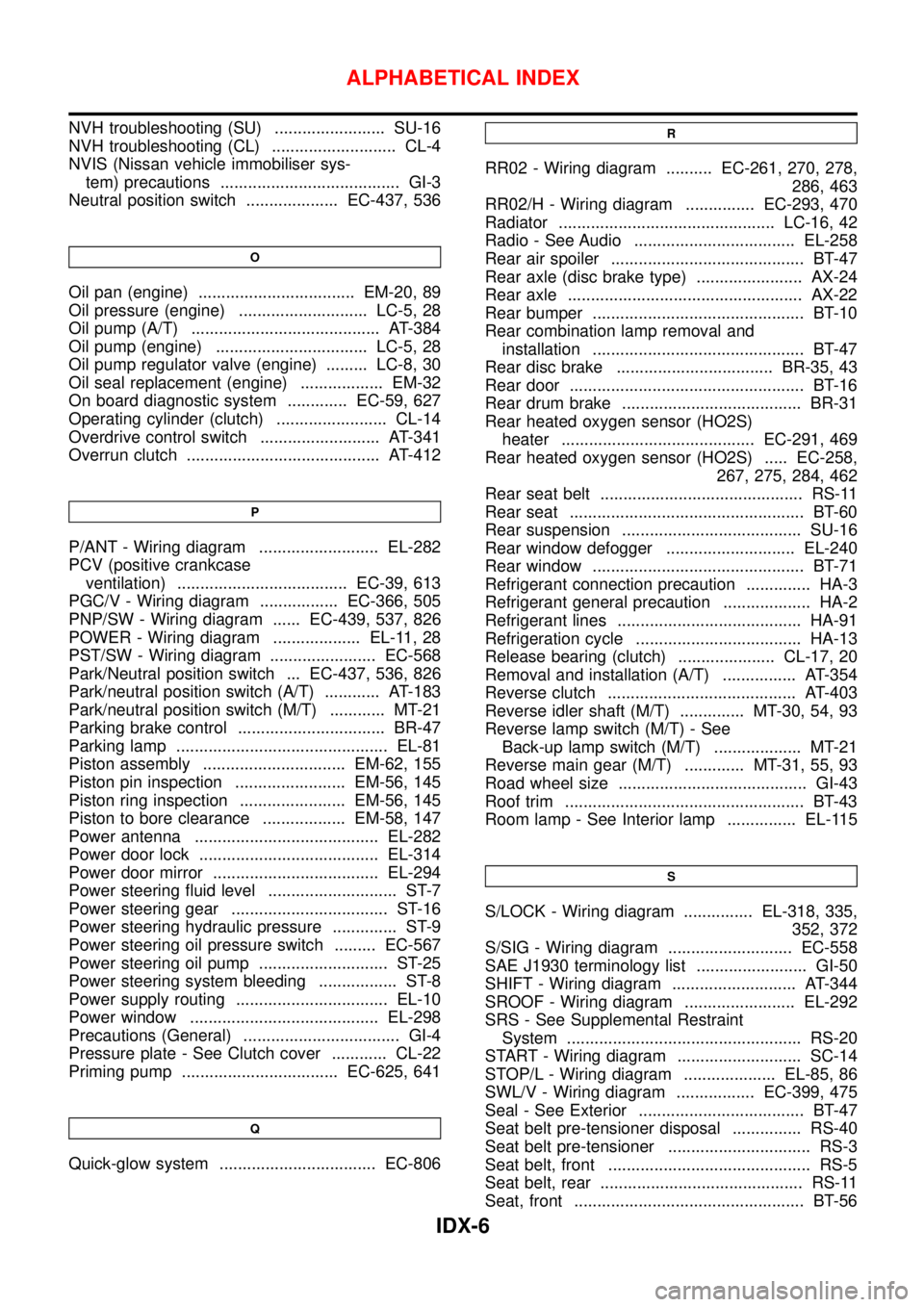
NVH troubleshooting (SU) ........................ SU-16
NVH troubleshooting (CL) ........................... CL-4
NVIS (Nissan vehicle immobiliser sys-
tem) precautions ....................................... GI-3
Neutral position switch .................... EC-437, 536
O
Oil pan (engine) .................................. EM-20, 89
Oil pressure (engine) ............................ LC-5, 28
Oil pump (A/T) ......................................... AT-384
Oil pump (engine) ................................. LC-5, 28
Oil pump regulator valve (engine) ......... LC-8, 30
Oil seal replacement (engine) .................. EM-32
On board diagnostic system ............. EC-59, 627
Operating cylinder (clutch) ........................ CL-14
Overdrive control switch .......................... AT-341
Overrun clutch .......................................... AT-412
P
P/ANT - Wiring diagram .......................... EL-282
PCV (positive crankcase
ventilation) ..................................... EC-39, 613
PGC/V - Wiring diagram ................. EC-366, 505
PNP/SW - Wiring diagram ...... EC-439, 537, 826
POWER - Wiring diagram ................... EL-11, 28
PST/SW - Wiring diagram ....................... EC-568
Park/Neutral position switch ... EC-437, 536, 826
Park/neutral position switch (A/T) ............ AT-183
Park/neutral position switch (M/T) ............ MT-21
Parking brake control ................................ BR-47
Parking lamp .............................................. EL-81
Piston assembly ............................... EM-62, 155
Piston pin inspection ........................ EM-56, 145
Piston ring inspection ....................... EM-56, 145
Piston to bore clearance .................. EM-58, 147
Power antenna ........................................ EL-282
Power door lock ....................................... EL-314
Power door mirror .................................... EL-294
Power steering fluid level ............................ ST-7
Power steering gear .................................. ST-16
Power steering hydraulic pressure .............. ST-9
Power steering oil pressure switch ......... EC-567
Power steering oil pump ............................ ST-25
Power steering system bleeding ................. ST-8
Power supply routing ................................. EL-10
Power window ......................................... EL-298
Precautions (General) .................................. GI-4
Pressure plate - See Clutch cover ............ CL-22
Priming pump .................................. EC-625, 641
Q
Quick-glow system .................................. EC-806
R
RR02 - Wiring diagram .......... EC-261, 270, 278,
286, 463
RR02/H - Wiring diagram ............... EC-293, 470
Radiator ............................................... LC-16, 42
Radio - See Audio ................................... EL-258
Rear air spoiler .......................................... BT-47
Rear axle (disc brake type) ....................... AX-24
Rear axle ................................................... AX-22
Rear bumper .............................................. BT-10
Rear combination lamp removal and
installation .............................................. BT-47
Rear disc brake .................................. BR-35, 43
Rear door ................................................... BT-16
Rear drum brake ....................................... BR-31
Rear heated oxygen sensor (HO2S)
heater .......................................... EC-291, 469
Rear heated oxygen sensor (HO2S) ..... EC-258,
267, 275, 284, 462
Rear seat belt ............................................ RS-11
Rear seat ................................................... BT-60
Rear suspension ....................................... SU-16
Rear window defogger ............................ EL-240
Rear window .............................................. BT-71
Refrigerant connection precaution .............. HA-3
Refrigerant general precaution ................... HA-2
Refrigerant lines ........................................ HA-91
Refrigeration cycle .................................... HA-13
Release bearing (clutch) ..................... CL-17, 20
Removal and installation (A/T) ................ AT-354
Reverse clutch ......................................... AT-403
Reverse idler shaft (M/T) .............. MT-30, 54, 93
Reverse lamp switch (M/T) - See
Back-up lamp switch (M/T) ................... MT-21
Reverse main gear (M/T) ............. MT-31, 55, 93
Road wheel size ......................................... GI-43
Roof trim .................................................... BT-43
Room lamp - See Interior lamp ............... EL-115
S
S/LOCK - Wiring diagram ............... EL-318, 335,
352, 372
S/SIG - Wiring diagram ........................... EC-558
SAE J1930 terminology list ........................ GI-50
SHIFT - Wiring diagram ........................... AT-344
SROOF - Wiring diagram ........................ EL-292
SRS - See Supplemental Restraint
System ................................................... RS-20
START - Wiring diagram ........................... SC-14
STOP/L - Wiring diagram .................... EL-85, 86
SWL/V - Wiring diagram ................. EC-399, 475
Seal - See Exterior .................................... BT-47
Seat belt pre-tensioner disposal ............... RS-40
Seat belt pre-tensioner ............................... RS-3
Seat belt, front ............................................ RS-5
Seat belt, rear ............................................ RS-11
Seat, front .................................................. BT-56
ALPHABETICAL INDEX
IDX-6
Page 2507 of 2898
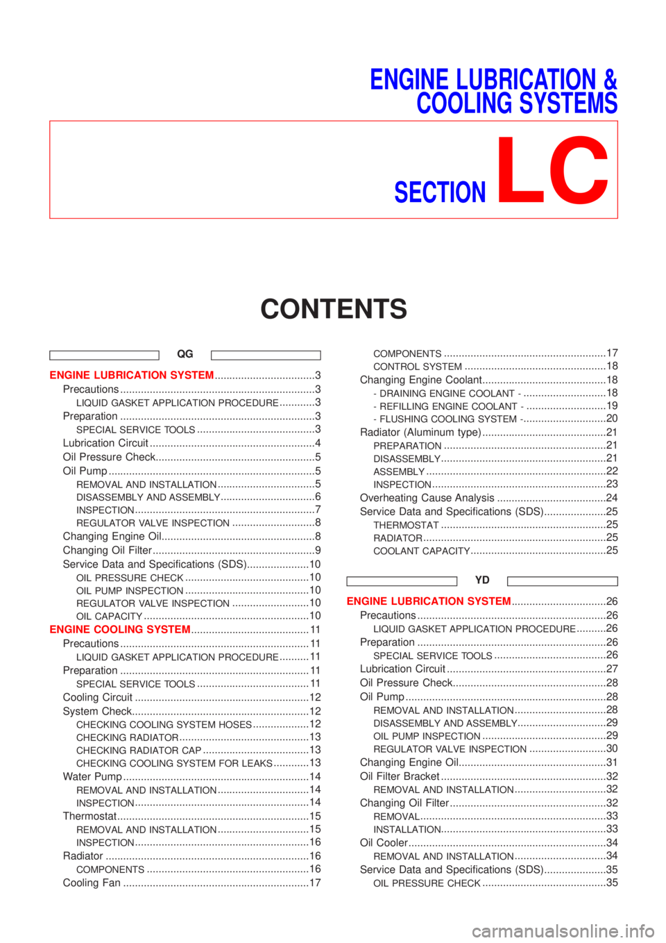
ENGINE LUBRICATION &
COOLING SYSTEMS
SECTION
LC
CONTENTS
QG
ENGINE LUBRICATION SYSTEM..................................3
Precautions ..................................................................3
LIQUID GASKET APPLICATION PROCEDURE............3
Preparation ..................................................................3
SPECIAL SERVICE TOOLS........................................3
Lubrication Circuit ........................................................4
Oil Pressure Check......................................................5
Oil Pump ......................................................................5
REMOVAL AND INSTALLATION.................................5
DISASSEMBLY AND ASSEMBLY................................6
INSPECTION.............................................................7
REGULATOR VALVE INSPECTION............................8
Changing Engine Oil....................................................8
Changing Oil Filter .......................................................9
Service Data and Specifications (SDS).....................10
OIL PRESSURE CHECK..........................................10
OIL PUMP INSPECTION..........................................10
REGULATOR VALVE INSPECTION..........................10
OIL CAPACITY........................................................10
ENGINE COOLING SYSTEM........................................ 11
Precautions ................................................................ 11
LIQUID GASKET APPLICATION PROCEDURE.......... 11
Preparation ................................................................ 11
SPECIAL SERVICE TOOLS...................................... 11
Cooling Circuit ...........................................................12
System Check............................................................12
CHECKING COOLING SYSTEM HOSES...................12
CHECKING RADIATOR............................................13
CHECKING RADIATOR CAP....................................13
CHECKING COOLING SYSTEM FOR LEAKS............13
Water Pump ...............................................................14
REMOVAL AND INSTALLATION...............................14
INSPECTION...........................................................14
Thermostat .................................................................15
REMOVAL AND INSTALLATION...............................15
INSPECTION...........................................................16
Radiator .....................................................................16
COMPONENTS.......................................................16
Cooling Fan ...............................................................17
COMPONENTS.......................................................17
CONTROL SYSTEM................................................18
Changing Engine Coolant..........................................18
- DRAINING ENGINE COOLANT -............................18
- REFILLING ENGINE COOLANT -...........................19
- FLUSHING COOLING SYSTEM -............................20
Radiator (Aluminum type) ..........................................21
PREPARATION.......................................................21
DISASSEMBLY........................................................21
ASSEMBLY.............................................................22
INSPECTION...........................................................23
Overheating Cause Analysis .....................................24
Service Data and Specifications (SDS).....................25
THERMOSTAT........................................................25
RADIATOR..............................................................25
COOLANT CAPACITY..............................................25
YD
ENGINE LUBRICATION SYSTEM................................26
Precautions ................................................................26
LIQUID GASKET APPLICATION PROCEDURE..........26
Preparation ................................................................26
SPECIAL SERVICE TOOLS......................................26
Lubrication Circuit ......................................................27
Oil Pressure Check....................................................28
Oil Pump ....................................................................28
REMOVAL AND INSTALLATION...............................28
DISASSEMBLY AND ASSEMBLY..............................29
OIL PUMP INSPECTION..........................................29
REGULATOR VALVE INSPECTION..........................30
Changing Engine Oil..................................................31
Oil Filter Bracket ........................................................32
REMOVAL AND INSTALLATION...............................32
Changing Oil Filter .....................................................32
REMOVAL...............................................................33
INSTALLATION........................................................33
Oil Cooler ...................................................................34
REMOVAL AND INSTALLATION...............................34
Service Data and Specifications (SDS).....................35
OIL PRESSURE CHECK..........................................35