2001 NISSAN ALMERA N16 Changing
[x] Cancel search: ChangingPage 650 of 2493
SEF552W
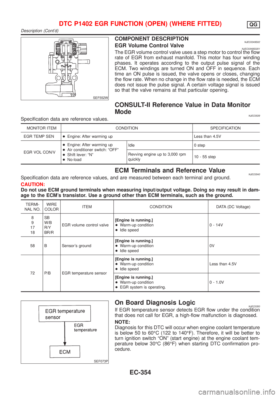
COMPONENT DESCRIPTIONNJEC0349S02EGR Volume Control ValveNJEC0349S0201The EGR volume control valve uses a step motor to control the flow
rate of EGR from exhaust manifold. This motor has four winding
phases. It operates according to the output pulse signal of the
ECM. Two windings are turned ON and OFF in sequence. Each
time an ON pulse is issued, the valve opens or closes, changing
the flow rate. When no change in the flow rate is needed, the ECM
does not issue the pulse signal. A certain voltage signal is issued
so that the valve remains at that particular opening.
CONSULT-II Reference Value in Data Monitor
Mode
NJEC0539Specification data are reference values.
MONITOR ITEM CONDITION SPECIFICATION
EGR TEMP SEN+Engine: After warming up Less than 4.5V
EGR VOL CON/V+Engine: After warming up
+Air conditioner switch: ªOFFº
+Shift lever: ªNº
+No-loadIdle 0 step
Revving engine up to 3,000 rpm
quickly10 - 55 step
ECM Terminals and Reference ValueNJEC0540Specification data are reference values, and are measured between each terminal and ground.
CAUTION:
Do not use ECM ground terminals when measuring input/output voltage. Doing so may result in dam-
age to the ECM's transistor. Use a ground other than ECM terminals, such as the ground.
TERMI-
NAL NO.WIRE
COLORITEM CONDITION DATA (DC Voltage)
8
9
17
18SB
W/B
R/Y
BR/REGR volume control valve[Engine is running.]
+Warm-up condition
+Idle speed0 - 14V
58 B Sensor's ground[Engine is running.]
+Warm-up condition
+Idle speed0V
72 P/B EGR temperature sensor[Engine is running.]
+Warm-up condition
+Idle speedLess than 4.5V
[Engine is running.]
+Warm-up condition
+EGR system is operating.0 - 1.0V
SEF073P
On Board Diagnosis LogicNJEC0350If EGR temperature sensor detects EGR flow under the condition
that does not call for EGR, a high-flow malfunction is diagnosed.
NOTE:
Diagnosis for this DTC will occur when engine coolant temperature
is below 50 to 60ÉC (122 to 140ÉF). Therefore, it will be better to
turn ignition switch ªONº (start engine) at the engine coolant tem-
perature below 30ÉC (86ÉF) when starting DTC confirmation pro-
cedure.
DTC P1402 EGR FUNCTION (OPEN) (WHERE FITTED)QG
Description (Cont'd)
EC-354
Page 690 of 2493
SEF058X
JEF835Z
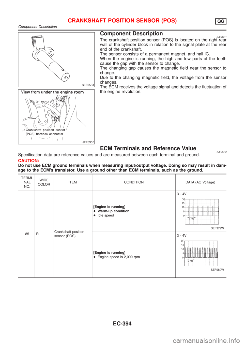
Component DescriptionNJEC1741The crankshaft position sensor (POS) is located on the right-rear
wall of the cylinder block in relation to the signal plate at the rear
end of the crankshaft.
The sensor consists of a permanent magnet, and hall IC.
When the engine is running, the high and low parts of the teeth
cause the gap with the sensor to change.
The changing gap causes the magnetic field near the sensor to
change.
Due to the changing magnetic field, the voltage from the sensor
changes.
The ECM receives the voltage signal and detects the fluctuation of
the engine revolution.
ECM Terminals and Reference ValueNJEC1742Specification data are reference values and are measured between each terminal and ground.
CAUTION:
Do not use ECM ground terminals when measuring input/output voltage. Doing so may result in dam-
age to the ECM's transistor. Use a ground other than ECM terminals, such as the ground.
TERMI-
NAL
NO.WIRE
COLORITEM CONDITION DATA (AC Voltage)
85 RCrankshaft position
sensor (POS)[Engine is running]
+Warm-up condition
+Idle speed3-4V
SEF979W
[Engine is running]
+Engine speed is 2,000 rpm3-4V
SEF980W
CRANKSHAFT POSITION SENSOR (POS)QG
Component Description
EC-394
Page 697 of 2493
SEF552W
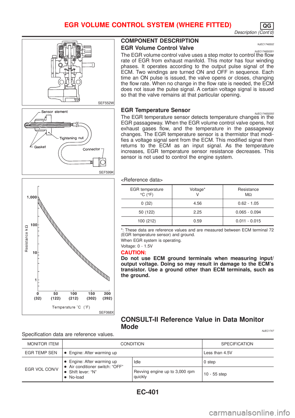
COMPONENT DESCRIPTIONNJEC1746S02EGR Volume Control ValveNJEC1746S0201The EGR volume control valve uses a step motor to control the flow
rate of EGR from exhaust manifold. This motor has four winding
phases. It operates according to the output pulse signal of the
ECM. Two windings are turned ON and OFF in sequence. Each
time an ON pulse is issued, the valve opens or closes, changing
the flow rate. When no change in the flow rate is needed, the ECM
does not issue the pulse signal. A certain voltage signal is issued
so that the valve remains at that particular opening.
SEF599K
EGR Temperature SensorNJEC1746S0202The EGR temperature sensor detects temperature changes in the
EGR passageway. When the EGR volume control valve opens, hot
exhaust gases flow, and the temperature in the passageway
changes. The EGR temperature sensor is a thermistor that modi-
fies a voltage signal sent from the ECM. This modified signal then
returns to the ECM as an input signal. As the temperature
increases, EGR temperature sensor resistance decreases. This
sensor is not used to control the engine system.
SEF068X
EGR temperature
ÉC (ÉF)Voltage*
VResistance
MW
0 (32) 4.56 0.62 - 1.05
50 (122) 2.25 0.065 - 0.094
100 (212) 0.59 0.011 - 0.015
*: These data are reference values and are measured between ECM terminal 72
(EGR temperature sensor) and ground.
When EGR system is operating.
Voltage: 0 - 1.5V
CAUTION:
Do not use ECM ground terminals when measuring input/
output voltage. Doing so may result in damage to the ECM's
transistor. Use a ground other than ECM terminals, such as
the ground.
CONSULT-II Reference Value in Data Monitor
Mode
NJEC1747Specification data are reference values.
MONITOR ITEM CONDITION SPECIFICATION
EGR TEMP SEN+Engine: After warming up Less than 4.5V
EGR VOL CON/V+Engine: After warming up
+Air conditioner switch: ªOFFº
+Shift lever: ªNº
+No-loadIdle 0 step
Revving engine up to 3,000 rpm
quickly10 - 55 step
EGR VOLUME CONTROL SYSTEM (WHERE FITTED)QG
Description (Cont'd)
EC-401
Page 813 of 2493
JEF365Y
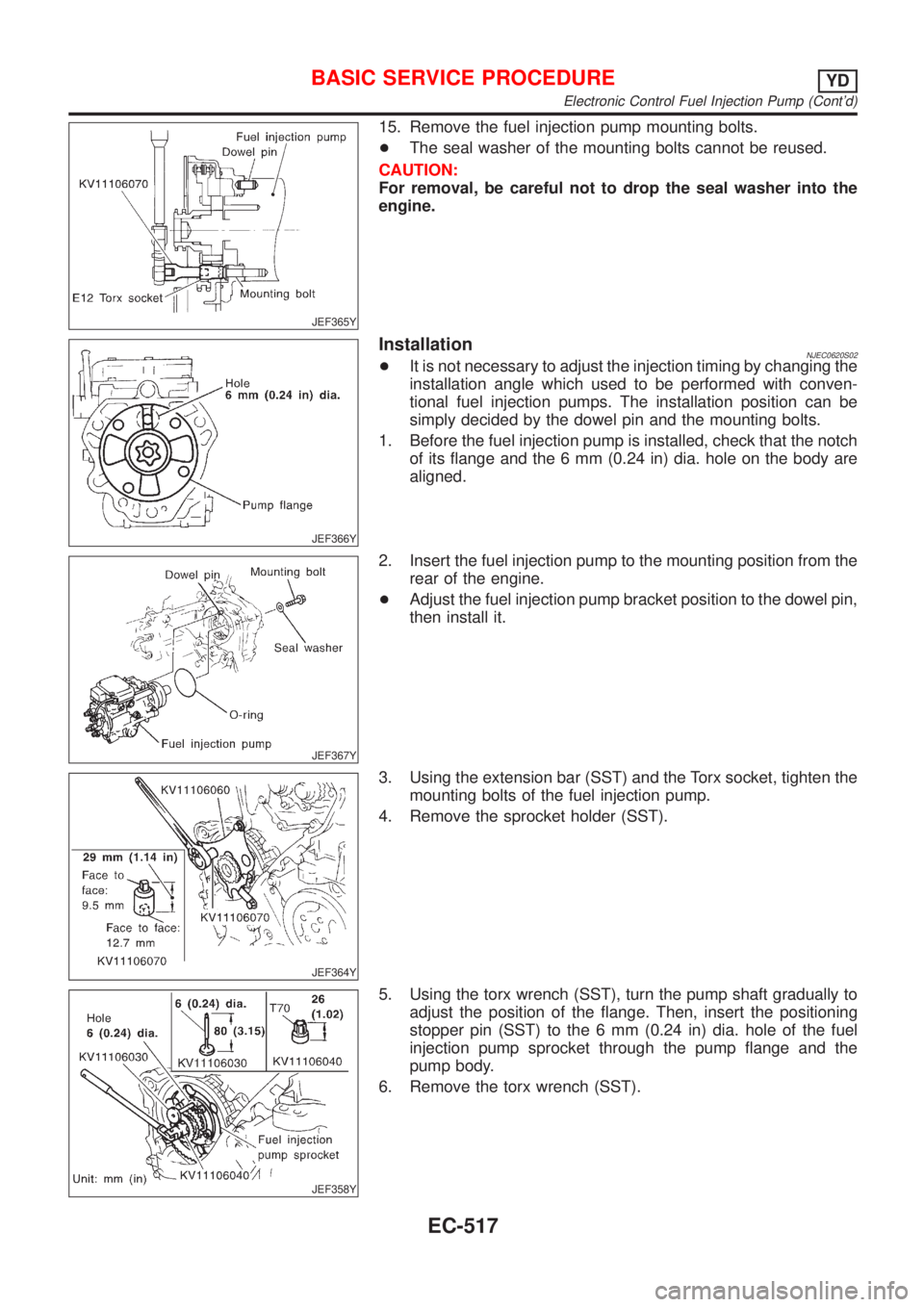
15. Remove the fuel injection pump mounting bolts.
+The seal washer of the mounting bolts cannot be reused.
CAUTION:
For removal, be careful not to drop the seal washer into the
engine.
JEF366Y
InstallationNJEC0620S02+It is not necessary to adjust the injection timing by changing the
installation angle which used to be performed with conven-
tional fuel injection pumps. The installation position can be
simply decided by the dowel pin and the mounting bolts.
1. Before the fuel injection pump is installed, check that the notch
of its flange and the 6 mm (0.24 in) dia. hole on the body are
aligned.
JEF367Y
2. Insert the fuel injection pump to the mounting position from the
rear of the engine.
+Adjust the fuel injection pump bracket position to the dowel pin,
then install it.
JEF364Y
3. Using the extension bar (SST) and the Torx socket, tighten the
mounting bolts of the fuel injection pump.
4. Remove the sprocket holder (SST).
JEF358Y
5. Using the torx wrench (SST), turn the pump shaft gradually to
adjust the position of the flange. Then, insert the positioning
stopper pin (SST) to the 6 mm (0.24 in) dia. hole of the fuel
injection pump sprocket through the pump flange and the
pump body.
6. Remove the torx wrench (SST).
BASIC SERVICE PROCEDUREYD
Electronic Control Fuel Injection Pump (Cont'd)
EC-517
Page 818 of 2493
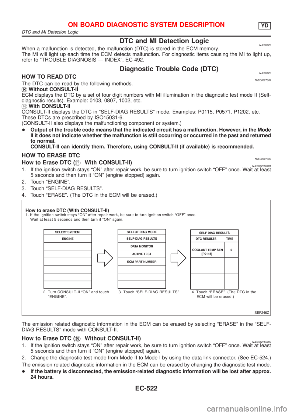
DTC and MI Detection LogicNJEC0626When a malfunction is detected, the malfunction (DTC) is stored in the ECM memory.
The MI will light up each time the ECM detects malfunction. For diagnostic items causing the MI to light up,
refer to ªTROUBLE DIAGNOSIS Ð INDEXº, EC-492.
Diagnostic Trouble Code (DTC)NJEC0627HOW TO READ DTCNJEC0627S01The DTC can be read by the following methods.
Without CONSULT-II
ECM displays the DTC by a set of four digit numbers with MI illumination in the diagnostic test mode II (Self-
diagnostic results). Example: 0103, 0807, 1002, etc.
With CONSULT-II
CONSULT-II displays the DTC in ªSELF-DIAG RESULTSº mode. Examples: P0115, P0571, P1202, etc.
These DTCs are prescribed by ISO15031-6.
(CONSULT-II also displays the malfunctioning component or system.)
+Output of the trouble code means that the indicated circuit has a malfunction. However, in the Mode
II it does not indicate whether the malfunction is still occurring or occurred in the past and returned
to normal.
CONSULT-II can identify them. Therefore, using CONSULT-II (if available) is recommended.
HOW TO ERASE DTCNJEC0627S02How to Erase DTC (With CONSULT-II)NJEC0627S02011. If the ignition switch stays ªONº after repair work, be sure to turn ignition switch ªOFFº once. Wait at least
5 seconds and then turn it ªONº (engine stopped) again.
2. Touch ªENGINEº.
3. Touch ªSELF-DIAG RESULTSº.
4. Touch ªERASEº. (The DTC in the ECM will be erased.)
SEF246Z
The emission related diagnostic information in the ECM can be erased by selecting ªERASEº in the ªSELF-
DIAG RESULTSº mode with CONSULT-II.
How to Erase DTC (Without CONSULT-II)NJEC0627S02021. If the ignition switch stays ªONº after repair work, be sure to turn ignition switch ªOFFº once. Wait at least
5 seconds and then turn it ªONº (engine stopped) again.
2. Change the diagnostic test mode from Mode II to Mode I by using the data link connector. (See EC-524.)
The emission related diagnostic information in the ECM can be erased by changing the diagnostic test mode.
+If the battery is disconnected, the emission-related diagnostic information will be lost after approx.
24 hours.
ON BOARD DIAGNOSTIC SYSTEM DESCRIPTIONYD
DTC and MI Detection Logic
EC-522
Page 902 of 2493

SEF437Y
DescriptionNJEC0672SYSTEM DESCRIPTIONNJEC0672S01The ECM and the electronic control fuel injection pump control unit
(abbreviated as the injection pump control unit) perform the real
time communication (signal exchange).
The ECM transmits the signals of the target fuel injection amount,
target fuel injection timing, and engine speed, etc., and receives
the signals of the pump speed and fuel temperature, etc. from the
injection pump control unit.
By those signals, the injection pump controls the optimum fuel
injection amount and injection timing of the spill valve and timing
control valve.
Injection pump control unit has an on board diagnostic system,
which detects malfunctions related to sensors or actuators built-into
electronic control fuel injection pump. These malfunction informa-
tion are transferred through the line (circuit) from injection pump
control unit to ECM.
FUEL INJECTION AMOUNT CONTROLNJEC0672S02In accordance with the target fuel injection amount signal from the
ECM, the injection amount is controlled by controlling the spill valve
in the injection pump and by changing the needle opening time.
FUEL INJECTION TIMING CONTROLNJEC0672S03Based on the target fuel injection timing signal from the ECM, the
injection timing is controlled in accordance with the timer spring by
performing the duty control of the timing control valve in the injec-
tion pump and by adjusting the pressure of the timer piston high
pressure chamber.
FUEL TEMPERATURE SENSORNJEC0672S04The sensor detects the fuel temperature in the injection pump and
calibrates the injection amount change by the fuel temperature.
CAMSHAFT POSITION SENSORNJEC0672S05The sensor detects the passing of the protrusion on the sensor
wheel in the injection pump by the semiconductor magnetic resis-
tance element sensor. The camshaft position sensor synchronizes
with the cam ring, and detects the actual advance amount. The
injection pump control unit measures the injection pump revolution
by the signal of the camshaft position sensor.
CONSULT-II Reference Value in Data Monitor
Mode
NJEC0673Remarks: Specification data are reference values.
MONITOR ITEM CONDITION SPECIFICATION
FUEL TEMP SEN+Engine: After warming up More than 40ÉC (104ÉF)
SPILL/V+Engine: After warming up, idle the engine. Approx. 12 - 13ÉCA
INT/A VOLUME+Engine: After warming up, idle the engine. Approx. 150 - 450 mg/st
F/CUT SIGNAL+Engine: After warming up Idle ON
DTC P1180 P9´FUEL TEMP SENYD
Description
EC-606
Page 908 of 2493
SEF437Y
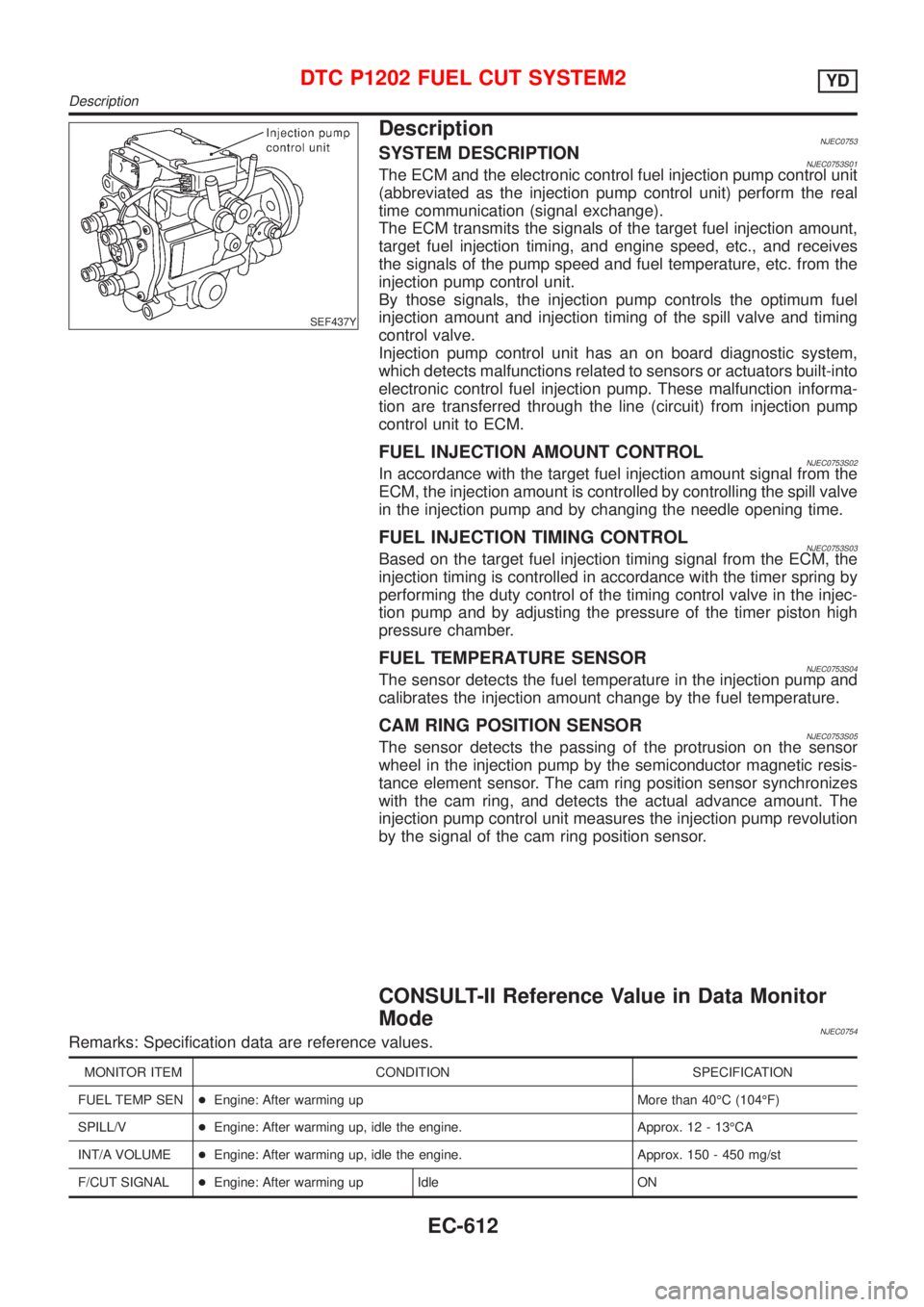
DescriptionNJEC0753SYSTEM DESCRIPTIONNJEC0753S01The ECM and the electronic control fuel injection pump control unit
(abbreviated as the injection pump control unit) perform the real
time communication (signal exchange).
The ECM transmits the signals of the target fuel injection amount,
target fuel injection timing, and engine speed, etc., and receives
the signals of the pump speed and fuel temperature, etc. from the
injection pump control unit.
By those signals, the injection pump controls the optimum fuel
injection amount and injection timing of the spill valve and timing
control valve.
Injection pump control unit has an on board diagnostic system,
which detects malfunctions related to sensors or actuators built-into
electronic control fuel injection pump. These malfunction informa-
tion are transferred through the line (circuit) from injection pump
control unit to ECM.
FUEL INJECTION AMOUNT CONTROLNJEC0753S02In accordance with the target fuel injection amount signal from the
ECM, the injection amount is controlled by controlling the spill valve
in the injection pump and by changing the needle opening time.
FUEL INJECTION TIMING CONTROLNJEC0753S03Based on the target fuel injection timing signal from the ECM, the
injection timing is controlled in accordance with the timer spring by
performing the duty control of the timing control valve in the injec-
tion pump and by adjusting the pressure of the timer piston high
pressure chamber.
FUEL TEMPERATURE SENSORNJEC0753S04The sensor detects the fuel temperature in the injection pump and
calibrates the injection amount change by the fuel temperature.
CAM RING POSITION SENSORNJEC0753S05The sensor detects the passing of the protrusion on the sensor
wheel in the injection pump by the semiconductor magnetic resis-
tance element sensor. The cam ring position sensor synchronizes
with the cam ring, and detects the actual advance amount. The
injection pump control unit measures the injection pump revolution
by the signal of the cam ring position sensor.
CONSULT-II Reference Value in Data Monitor
Mode
NJEC0754Remarks: Specification data are reference values.
MONITOR ITEM CONDITION SPECIFICATION
FUEL TEMP SEN+Engine: After warming up More than 40ÉC (104ÉF)
SPILL/V+Engine: After warming up, idle the engine. Approx. 12 - 13ÉCA
INT/A VOLUME+Engine: After warming up, idle the engine. Approx. 150 - 450 mg/st
F/CUT SIGNAL+Engine: After warming up Idle ON
DTC P1202 FUEL CUT SYSTEM2YD
Description
EC-612
Page 915 of 2493
![NISSAN ALMERA N16 2001 Electronic Repair Manual TERMI-
NAL
NO.WIRE
COLORITEM CONDITION DATA(DC Voltage)
221 LG/B Cooling fan relay (High)[Engine is running]
+Cooling fans are not operating
+Cooling fans are operating at low speedBATTERY VOLTAGE
(11 NISSAN ALMERA N16 2001 Electronic Repair Manual TERMI-
NAL
NO.WIRE
COLORITEM CONDITION DATA(DC Voltage)
221 LG/B Cooling fan relay (High)[Engine is running]
+Cooling fans are not operating
+Cooling fans are operating at low speedBATTERY VOLTAGE
(11](/manual-img/5/57351/w960_57351-914.png)
TERMI-
NAL
NO.WIRE
COLORITEM CONDITION DATA(DC Voltage)
221 LG/B Cooling fan relay (High)[Engine is running]
+Cooling fans are not operating
+Cooling fans are operating at low speedBATTERY VOLTAGE
(11 - 14V)
[Engine is running]
+Cooling fans are operating at high speedApproximately 0.1V
On Board Diagnosis LogicNJEC0663This diagnosis continuously monitors the engine coolant temperature.
If the cooling fan or another component in the cooling system malfunctions, engine coolant temperature will
rise.
When the engine coolant temperature reaches an abnormally high temperature condition, a malfunction is
indicated.
DTC Malfunction is detected when ... Check Items (Possible Cause)
P1217
0208+Cooling fan does not operate properly (Overheat).
+Cooling fan system does not operate properly
(Overheat).
+Engine coolant was not added to the system using
the proper filling method.+Harness or connectors
(The cooling fan circuit is open or shorted.)
+Cooling fan
+Radiator hose
+Radiator
+Radiator cap
+Water pump
+Thermostat
+Engine coolant temperature sensor
For more information, refer to ªMAIN 12 CAUSES OF
OVERHEATINGº, EC-633.
CAUTION:
When a malfunction is indicated, be sure to replace the coolant following the procedure in the LC-43,
ªChanging Engine Coolantº. Also, replace the engine oil.
1) Fill radiator with coolant up to specified level with a filling speed of 2 liters per minute. Be sure
to use coolant with the proper mixture ratio. Refer to MA-22, ªEngine Coolant Mixture Ratioº.
2) After refilling coolant, run engine to ensure that no water-flow noise is emitted.
DTC P1217 OVER HEATYD
ECM Terminals and Reference Value (Cont'd)
EC-619