2001 NISSAN ALMERA N16 Changing
[x] Cancel search: ChangingPage 1128 of 2493
SMT685DC
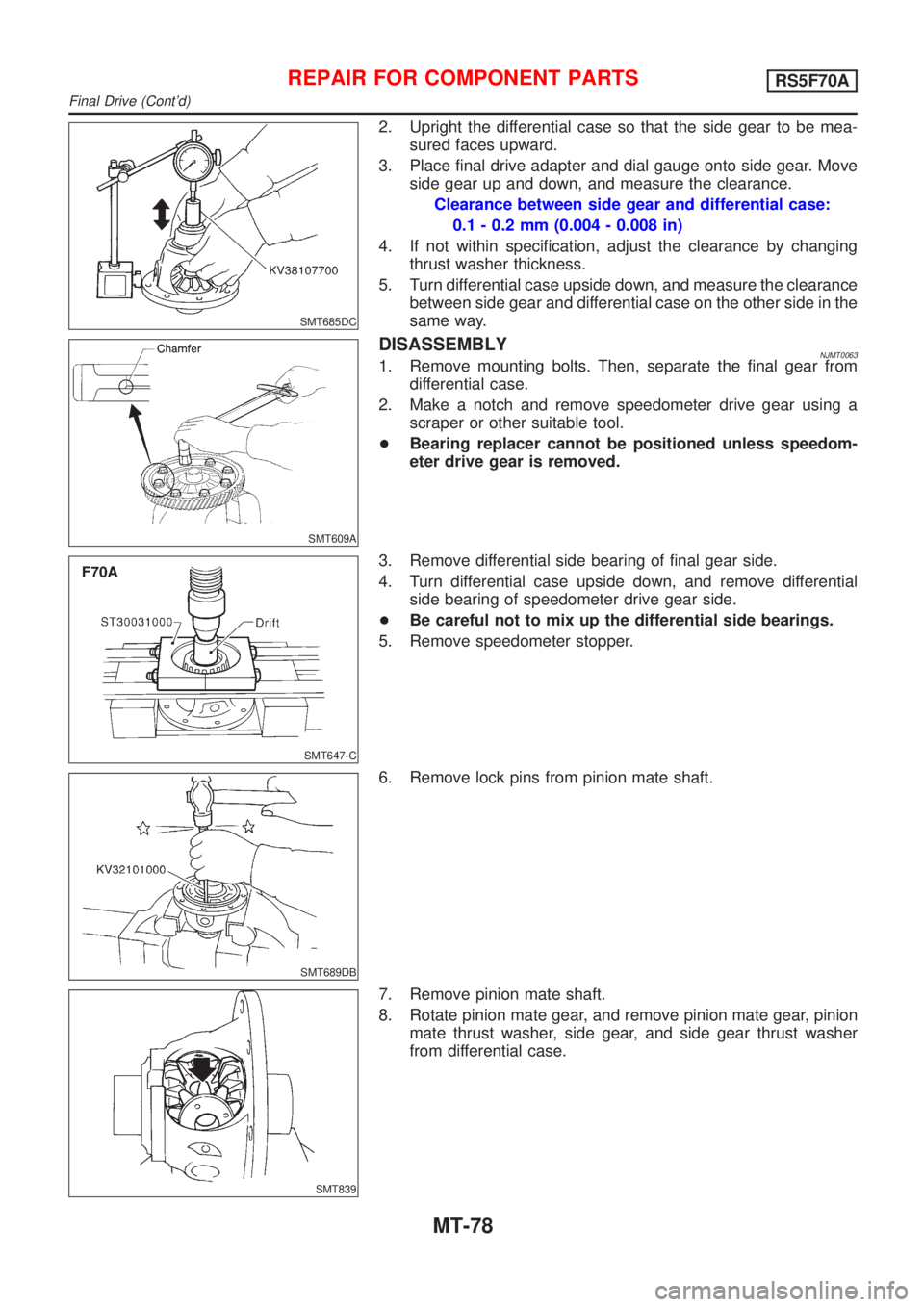
2. Upright the differential case so that the side gear to be mea-
sured faces upward.
3. Place final drive adapter and dial gauge onto side gear. Move
side gear up and down, and measure the clearance.
Clearance between side gear and differential case:
0.1 - 0.2 mm (0.004 - 0.008 in)
4. If not within specification, adjust the clearance by changing
thrust washer thickness.
5. Turn differential case upside down, and measure the clearance
between side gear and differential case on the other side in the
same way.
SMT609A
DISASSEMBLYNJMT00631. Remove mounting bolts. Then, separate the final gear from
differential case.
2. Make a notch and remove speedometer drive gear using a
scraper or other suitable tool.
+Bearing replacer cannot be positioned unless speedom-
eter drive gear is removed.
SMT647-C
3. Remove differential side bearing of final gear side.
4. Turn differential case upside down, and remove differential
side bearing of speedometer drive gear side.
+Be careful not to mix up the differential side bearings.
5. Remove speedometer stopper.
SMT689DB
6. Remove lock pins from pinion mate shaft.
SMT839
7. Remove pinion mate shaft.
8. Rotate pinion mate gear, and remove pinion mate gear, pinion
mate thrust washer, side gear, and side gear thrust washer
from differential case.
REPAIR FOR COMPONENT PARTSRS5F70A
Final Drive (Cont'd)
MT-78
Page 1158 of 2493
SMT062A
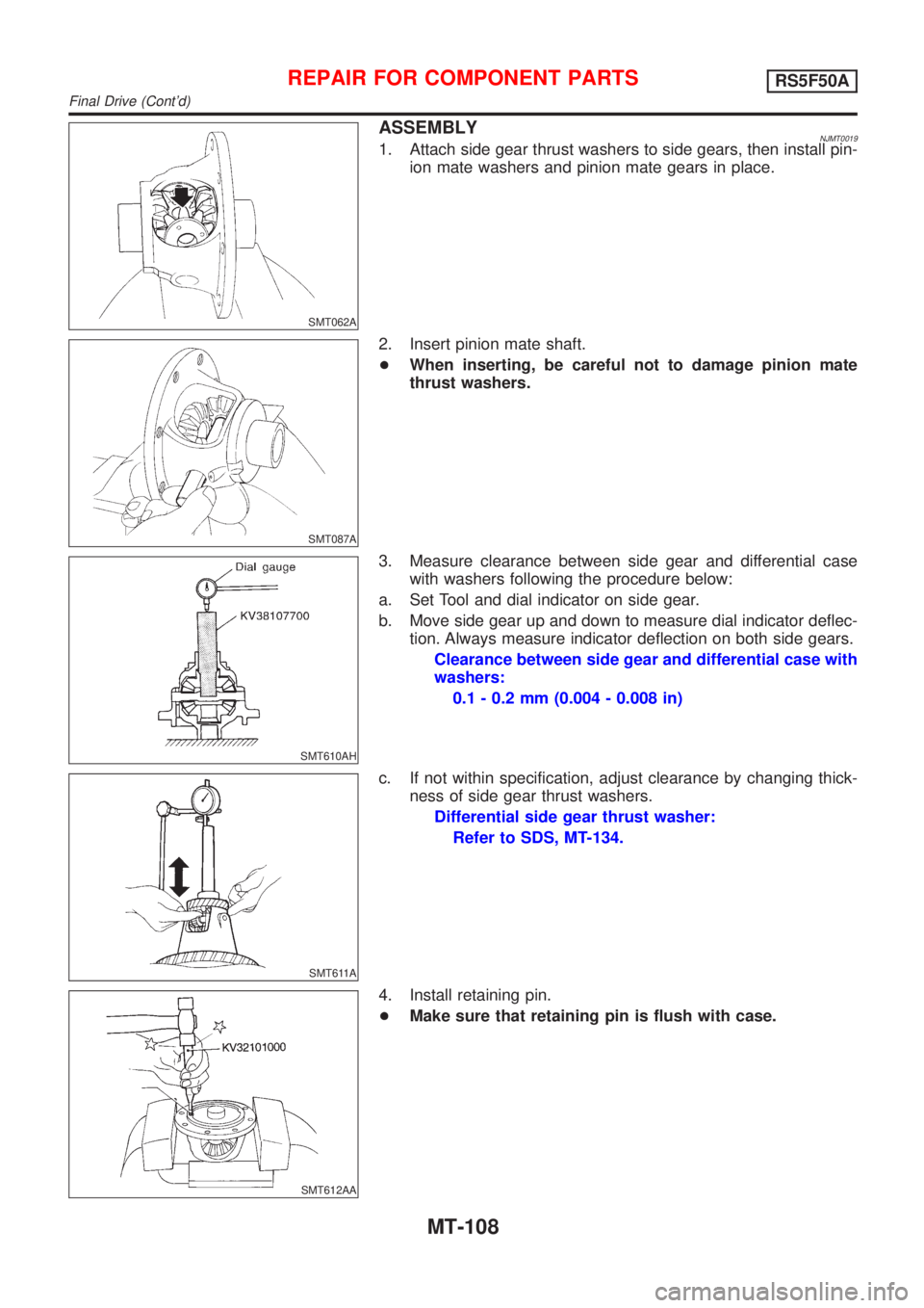
ASSEMBLYNJMT00191. Attach side gear thrust washers to side gears, then install pin-
ion mate washers and pinion mate gears in place.
SMT087A
2. Insert pinion mate shaft.
+When inserting, be careful not to damage pinion mate
thrust washers.
SMT610AH
3. Measure clearance between side gear and differential case
with washers following the procedure below:
a. Set Tool and dial indicator on side gear.
b. Move side gear up and down to measure dial indicator deflec-
tion. Always measure indicator deflection on both side gears.
Clearance between side gear and differential case with
washers:
0.1 - 0.2 mm (0.004 - 0.008 in)
SMT611A
c. If not within specification, adjust clearance by changing thick-
ness of side gear thrust washers.
Differential side gear thrust washer:
Refer to SDS, MT-134.
SMT612AA
4. Install retaining pin.
+Make sure that retaining pin is flush with case.
REPAIR FOR COMPONENT PARTSRS5F50A
Final Drive (Cont'd)
MT-108
Page 1187 of 2493
AUTOMATIC TRANSAXLE
SECTION
AT
CONTENTS
EURO-OBD
TROUBLE DIAGNOSIS - INDEX....................................5
Alphabetical & P No. Index for DTC ...........................5
PRECAUTIONS...............................................................7
Supplemental Restraint System (SRS)²AIR
BAG²and²SEAT BELT PRE-TENSIONER²...............7
Precautions for On Board Diagnostic (EURO-
OBD) System of A/T and Engine - Euro-OBD - ..........7
Precautions ..................................................................7
Service Notice or Precautions .....................................9
Wiring Diagrams and Trouble Diagnosis ...................10
PREPARATION............................................................. 11
Special Service Tools ................................................ 11
Commercial Service Tools .........................................13
A/T FLUID......................................................................15
Checking A/T Fluid ....................................................15
Changing A/T Fluid ....................................................15
OVERALL SYSTEM......................................................16
A/T Electrical Parts Location .....................................16
Circuit Diagram ..........................................................17
Cross-sectional View - ...............................................18
Hydraulic Control Circuit ............................................19
Shift Mechanism ........................................................20
Control System ..........................................................29
Control Mechanism ....................................................30
Control Valve .............................................................35
EXCEPT FOR EURO-OBD
ON BOARD DIAGNOSTIC SYSTEM............................37
CONSULT-II ...............................................................37
Diagnostic Procedure Without CONSULT-II ..............42
EURO-OBD
ON BOARD DIAGNOSTIC SYSTEM
DESCRIPTION...............................................................48Introduction ................................................................48
EURO-OBD Function for A/T System .......................48
One or Two Trip Detection Logic of EURO-OBD ......48
EURO-OBD Diagnostic Trouble Code (DTC)............48
Malfunction Indicator (MI) ..........................................52
CONSULT-II ...............................................................52
Diagnostic Procedure Without CONSULT-II ..............61
EXCEPT FOR EURO-OBD
TROUBLE DIAGNOSIS -...............................................67
Introduction ................................................................67
Work Flow ..................................................................71
EURO-OBD
TROUBLE DIAGNOSIS - INTRODUCTION..................72
Introduction ................................................................72
Work Flow ..................................................................76
TROUBLE DIAGNOSIS - BASIC INSPECTION...........78
A/T Fluid Check .........................................................78
Stall Test ....................................................................78
Line Pressure Test .....................................................82
Road Test...................................................................83
TROUBLE DIAGNOSIS - GENERAL
DESCRIPTION.............................................................103
Symptom Chart ........................................................103
TCM Terminals and Reference Value...................... 116
TROUBLE DIAGNOSIS FOR POWER SUPPLY........121
Wiring Diagram - AT - MAIN ....................................121
Diagnostic Procedure ..............................................122
EXCEPT FOR EURO-OBD
VEHICLE SPEED SENSOR.A/T..................................124
Description ...............................................................124
Wiring Diagram - AT - VSSA/T ................................126
Diagnostic Procedure ..............................................127
Page 1195 of 2493
parts. Apply petroleum jelly to protect O-rings and seals, or
hold bearings and washers in place during assembly. Do not
use grease.
+Extreme care should be taken to avoid damage to O-rings,
seals and gaskets when assembling.
+After overhaul, refill the transaxle with new ATF.
+When the A/T drain plug is removed, only some of the fluid is
drained. Old A/T fluid will remain in torque converter and ATF
cooling system.
Always follow the procedures under ªChanging A/T Fluidº in the
AT section when changing A/T fluid. Refer to ªChanging A/T
Fluidº, AT-15.
Service Notice or PrecautionsNJAT0247FAIL-SAFENJAT0247S01The TCM has an electronic Fail-Safe (limp home mode). This allows the vehicle to be driven even if a major
electrical input/output device circuit is damaged.
Under Fail-Safe, the vehicle always runs in third gear, even with a shift lever position of ª1º, ª2º or ªDº. The
customer may complain of sluggish or poor acceleration.
When the ignition key is turned ªONº following Fail-Safe operation, O/D OFF indicator lamp blinks for about
8 seconds. (For EXCEPT FOR EURO-OBD; ªSELF-DIAGNOSTIC PROCEDURE (WITHOUT CONSULT-II)º,
refer to AT-42 and for EURO-OBD; ªTCM SELF-DIAGNOSTIC PROCEDURE (No Tools)º, refer to AT-61.)
Fail-Safe may occur without electrical circuit damage if the vehicle is driven under extreme conditions (such
as excessive wheel spin followed by sudden braking). To recover normal shift pattern, turn the ignition key
ªOFFº for 5 seconds, then ªONº.
The blinking of the O/D OFF indicator lamp for about 8 seconds will appear only once and be cleared. The
customer may resume normal driving conditions.
Always follow the ªWORK FLOWº [Refer to AT-71 (Except for Euro-OBD), AT-76 (EURO-OBD).]
The SELF-DIAGNOSIS results will be as follows:
The first SELF-DIAGNOSIS will indicate damage to the vehicle speed sensor or the revolution sensor.
During the next SELF-DIAGNOSIS, performed after checking the sensor, no damages will be indicated.
TORQUE CONVERTER SERVICENJAT0247S02The torque converter should be replaced under any of the following conditions:
+External leaks in the hub weld area.
+Converter hub is scored or damaged.
+Converter pilot is broken, damaged or fits poorly into crankshaft.
+Steel particles are found after flushing the cooler and cooler lines.
+Pump is damaged or steel particles are found in the converter.
+Vehicle has TCC shudder and/or no TCC apply. Replace only after all hydraulic and electrical diagnoses
have been made. (Converter clutch material may be glazed.)
+Converter is contaminated with engine coolant containing antifreeze.
+Internal failure of stator roller clutch.
+Heavy clutch debris due to overheating (blue converter).
+Steel particles or clutch lining material found in fluid filter or on magnet when no internal parts in unit are
worn or damaged Ð indicates that lining material came from converter.
The torque converter should not be replaced if:
PRECAUTIONS
Precautions (Cont'd)
AT-9
Page 1201 of 2493
SMA827CA
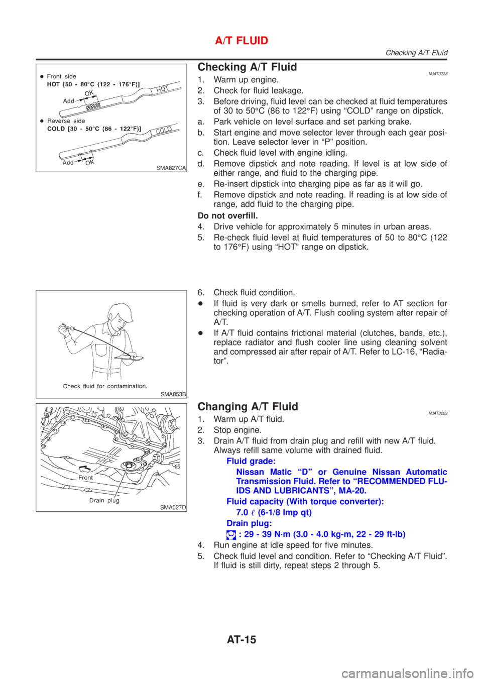
Checking A/T FluidNJAT02281. Warm up engine.
2. Check for fluid leakage.
3. Before driving, fluid level can be checked at fluid temperatures
of 30 to 50ÉC (86 to 122ÉF) using ªCOLDº range on dipstick.
a. Park vehicle on level surface and set parking brake.
b. Start engine and move selector lever through each gear posi-
tion. Leave selector lever in ªPº position.
c. Check fluid level with engine idling.
d. Remove dipstick and note reading. If level is at low side of
either range, and fluid to the charging pipe.
e. Re-insert dipstick into charging pipe as far as it will go.
f. Remove dipstick and note reading. If reading is at low side of
range, add fluid to the charging pipe.
Do not overfill.
4. Drive vehicle for approximately 5 minutes in urban areas.
5. Re-check fluid level at fluid temperatures of 50 to 80ÉC (122
to 176ÉF) using ªHOTº range on dipstick.
SMA853B
6. Check fluid condition.
+If fluid is very dark or smells burned, refer to AT section for
checking operation of A/T. Flush cooling system after repair of
A/T.
+If A/T fluid contains frictional material (clutches, bands, etc.),
replace radiator and flush cooler line using cleaning solvent
and compressed air after repair of A/T. Refer to LC-16, ªRadia-
torº.
SMA027D
Changing A/T FluidNJAT02291. Warm up A/T fluid.
2. Stop engine.
3. Drain A/T fluid from drain plug and refill with new A/T fluid.
Always refill same volume with drained fluid.
Fluid grade:
Nissan Matic ªDº or Genuine Nissan Automatic
Transmission Fluid. Refer to ªRECOMMENDED FLU-
IDS AND LUBRICANTSº, MA-20.
Fluid capacity (With torque converter):
7.0!(6-1/8 Imp qt)
Drain plug:
: 29 - 39 N´m (3.0 - 4.0 kg-m, 22 - 29 ft-lb)
4. Run engine at idle speed for five minutes.
5. Check fluid level and condition. Refer to ªChecking A/T Fluidº.
If fluid is still dirty, repeat steps 2 through 5.
A/T FLUID
Checking A/T Fluid
AT-15
Page 1275 of 2493
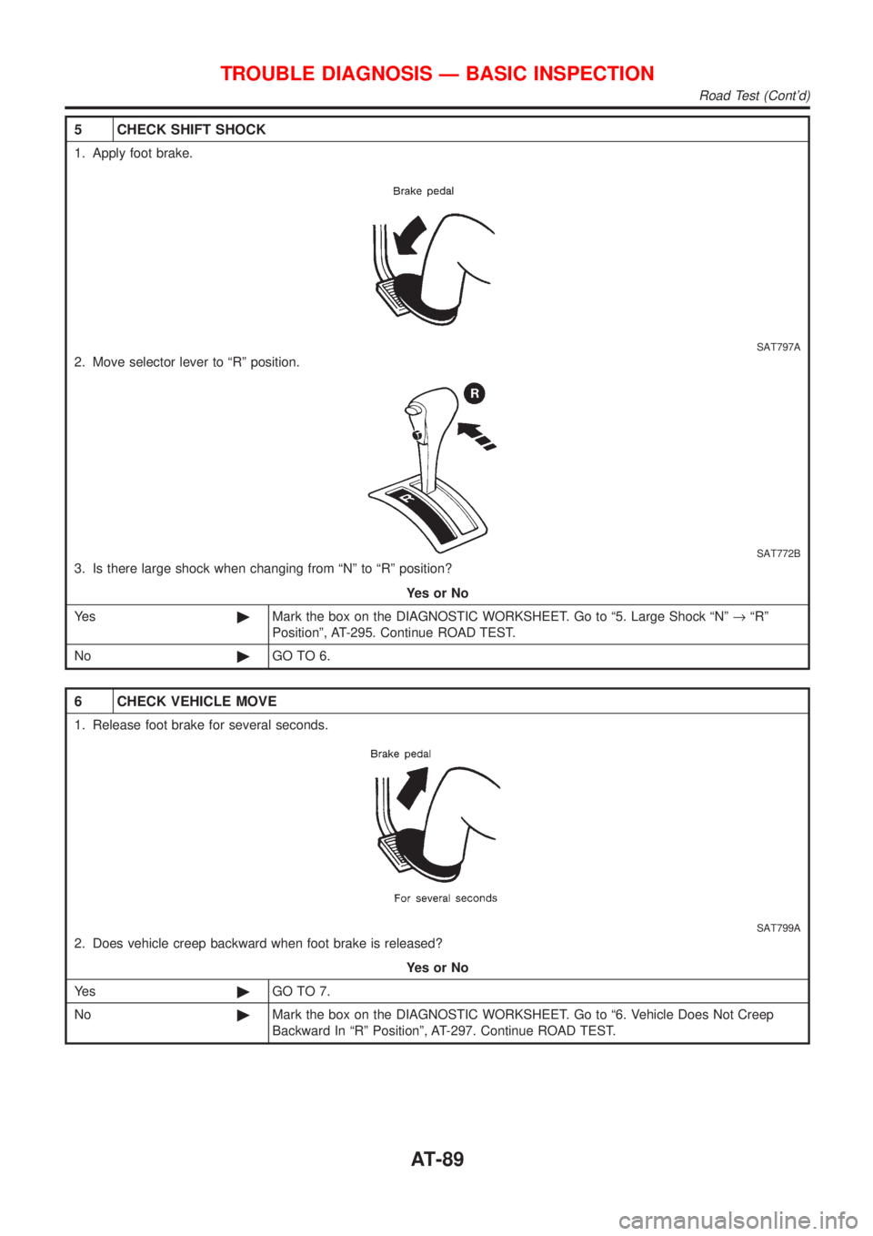
5 CHECK SHIFT SHOCK
1. Apply foot brake.
SAT797A
2. Move selector lever to ªRº position.
SAT772B
3. Is there large shock when changing from ªNº to ªRº position?
YesorNo
Ye s©Mark the box on the DIAGNOSTIC WORKSHEET. Go to ª5. Large Shock ªNº®ªRº
Positionº, AT-295. Continue ROAD TEST.
No©GO TO 6.
6 CHECK VEHICLE MOVE
1. Release foot brake for several seconds.
SAT799A
2. Does vehicle creep backward when foot brake is released?
YesorNo
Ye s©GO TO 7.
No©Mark the box on the DIAGNOSTIC WORKSHEET. Go to ª6. Vehicle Does Not Creep
Backward In ªRº Positionº, AT-297. Continue ROAD TEST.
TROUBLE DIAGNOSIS Ð BASIC INSPECTION
Road Test (Cont'd)
AT-89
Page 1289 of 2493
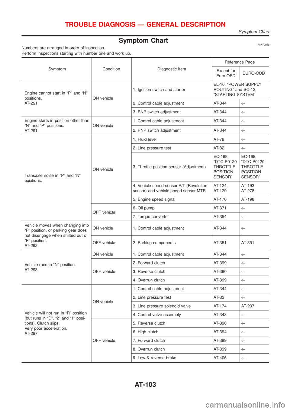
Symptom ChartNJAT0029Numbers are arranged in order of inspection.
Perform inspections starting with number one and work up.
Symptom Condition Diagnostic ItemReference Page
Except for
Euro-OBDEURO-OBD
Engine cannot start in ªPº and ªNº
positions.
AT-291ON vehicle1. Ignition switch and starterEL-10, ªPOWER SUPPLY
ROUTINGº and SC-13,
ªSTARTING SYSTEMº
2. Control cable adjustment AT-344¬
3. PNP switch adjustment AT-344¬
Engine starts in position other than
ªNº and ªPº positions.
AT-291ON vehicle1. Control cable adjustment AT-344¬
2. PNP switch adjustment AT-344¬
Transaxle noise in ªPº and ªNº
positions.ON vehicle1. Fluid level AT-78¬
2. Line pressure test AT-82¬
3. Throttle position sensor (Adjustment)EC-168,
ªDTC P0120
THROTTLE
POSITION
SENSORºEC-168,
ªDTC P0120
THROTTLE
POSITION
SENSORº
4. Vehicle speed sensor´A/T (Revolution
sensor) and vehicle speed sensor´MTRAT-124,
AT-129AT-193,
AT-278
5. Engine speed signal AT-170 AT-198
OFF vehicle6. Oil pump AT-371¬
7. Torque converter AT-354¬
Vehicle moves when changing into
ªPº position, or parking gear does
not disengage when shifted out of
ªPº position.
AT-292ON vehicle 1. Control cable adjustment AT-344¬
OFF vehicle 2. Parking components AT-351 AT-351
Vehicle runs in ªNº position.
AT-293ON vehicle 1. Control cable adjustment AT-344¬
OFF vehicle2. Forward clutch AT-399¬
3. Reverse clutch AT-390¬
4. Overrun clutch AT-399¬
Vehicle will not run in ªRº position
(but runs in ªDº, ª2º and ª1º posi-
tions). Clutch slips.
Very poor acceleration.
AT-297ON vehicle1. Control cable adjustment AT-344¬
2. Line pressure test AT-82¬
3. Line pressure solenoid valve AT-174 AT-237
4. Control valve assembly AT-343¬
OFF vehicle5. Reverse clutch AT-390¬
6. High clutch AT-394¬
7. Forward clutch AT-399¬
8. Overrun clutch AT-399¬
9. Low & reverse brake AT-406¬
TROUBLE DIAGNOSIS Ð GENERAL DESCRIPTION
Symptom Chart
AT-103
Page 1297 of 2493
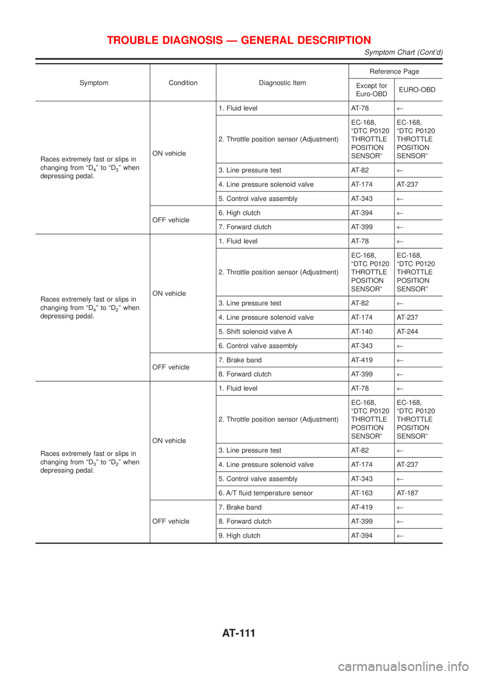
Symptom Condition Diagnostic ItemReference Page
Except for
Euro-OBDEURO-OBD
Races extremely fast or slips in
changing from ªD
4ºtoªD3º when
depressing pedal.ON vehicle1. Fluid level AT-78¬
2. Throttle position sensor (Adjustment)EC-168,
ªDTC P0120
THROTTLE
POSITION
SENSORºEC-168,
ªDTC P0120
THROTTLE
POSITION
SENSORº
3. Line pressure test AT-82¬
4. Line pressure solenoid valve AT-174 AT-237
5. Control valve assembly AT-343¬
OFF vehicle6. High clutch AT-394¬
7. Forward clutch AT-399¬
Races extremely fast or slips in
changing from ªD
4ºtoªD2º when
depressing pedal.ON vehicle1. Fluid level AT-78¬
2. Throttle position sensor (Adjustment)EC-168,
ªDTC P0120
THROTTLE
POSITION
SENSORºEC-168,
ªDTC P0120
THROTTLE
POSITION
SENSORº
3. Line pressure test AT-82¬
4. Line pressure solenoid valve AT-174 AT-237
5. Shift solenoid valve A AT-140 AT-244
6. Control valve assembly AT-343¬
OFF vehicle7. Brake band AT-419¬
8. Forward clutch AT-399¬
Races extremely fast or slips in
changing from ªD
3ºtoªD2º when
depressing pedal.ON vehicle1. Fluid level AT-78¬
2. Throttle position sensor (Adjustment)EC-168,
ªDTC P0120
THROTTLE
POSITION
SENSORºEC-168,
ªDTC P0120
THROTTLE
POSITION
SENSORº
3. Line pressure test AT-82¬
4. Line pressure solenoid valve AT-174 AT-237
5. Control valve assembly AT-343¬
6. A/T fluid temperature sensor AT-163 AT-187
OFF vehicle7. Brake band AT-419¬
8. Forward clutch AT-399¬
9. High clutch AT-394¬
TROUBLE DIAGNOSIS Ð GENERAL DESCRIPTION
Symptom Chart (Cont'd)
AT - 111