2001 NISSAN ALMERA N16 Changing
[x] Cancel search: ChangingPage 1511 of 2493
19. A/T Does Not Shift: 22®11, When Selector
Lever ª2º®ª1º Position
=NJAT0349SYMPTOM:
A/T does not shift from 2
2to 11when changing selector lever
from ª2º to ª1º position.
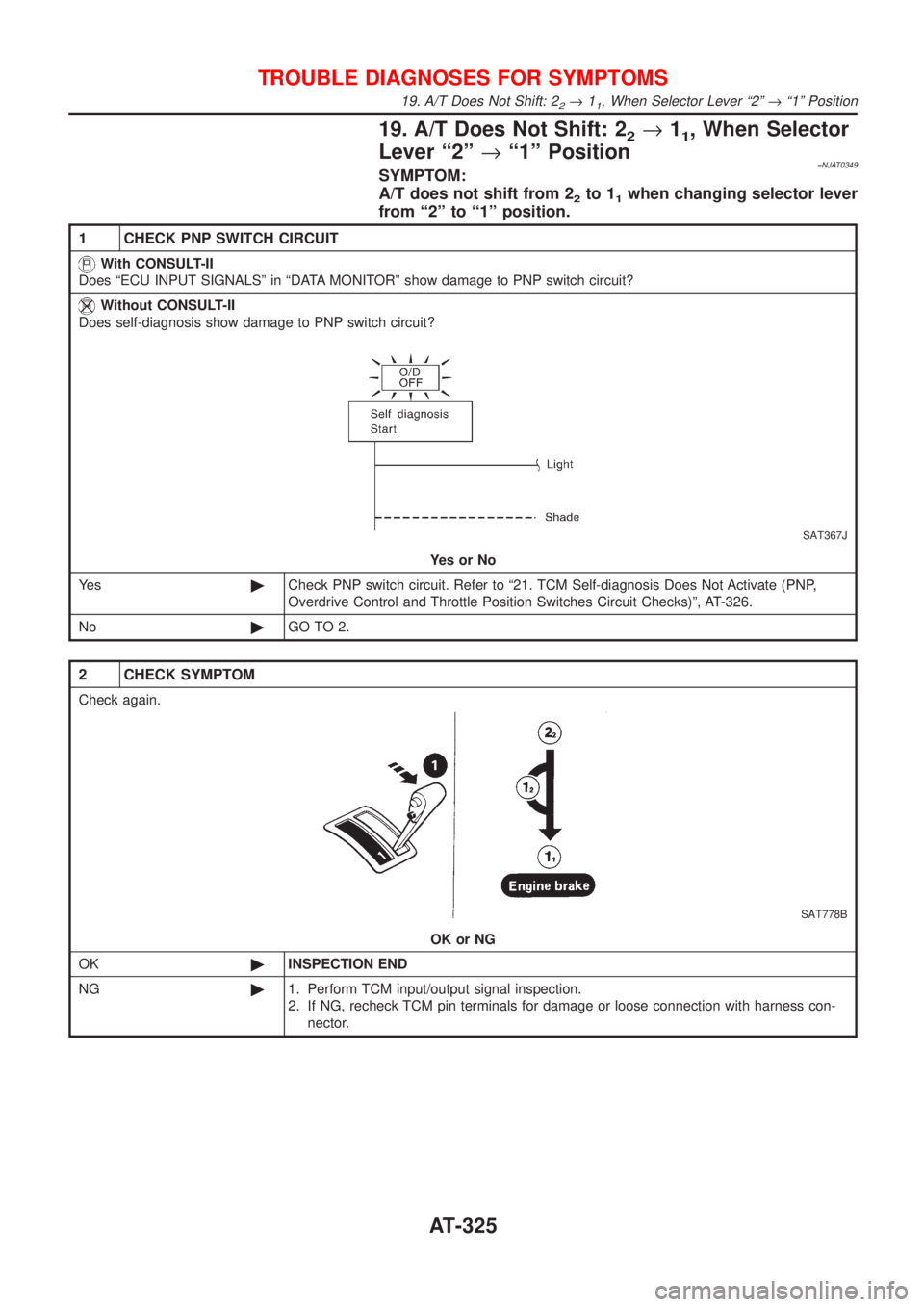
1 CHECK PNP SWITCH CIRCUIT
With CONSULT-II
Does ªECU INPUT SIGNALSº in ªDATA MONITORº show damage to PNP switch circuit?
Without CONSULT-II
Does self-diagnosis show damage to PNP switch circuit?
SAT367J
YesorNo
Ye s©Check PNP switch circuit. Refer to ª21. TCM Self-diagnosis Does Not Activate (PNP,
Overdrive Control and Throttle Position Switches Circuit Checks)º, AT-326.
No©GO TO 2.
2 CHECK SYMPTOM
Check again.
SAT778B
OK or NG
OK©INSPECTION END
NG©1. Perform TCM input/output signal inspection.
2. If NG, recheck TCM pin terminals for damage or loose connection with harness con-
nector.
TROUBLE DIAGNOSES FOR SYMPTOMS
19. A/T Does Not Shift: 22®11, When Selector Lever ª2º®ª1º Position
AT-325
Page 1612 of 2493
NAT056
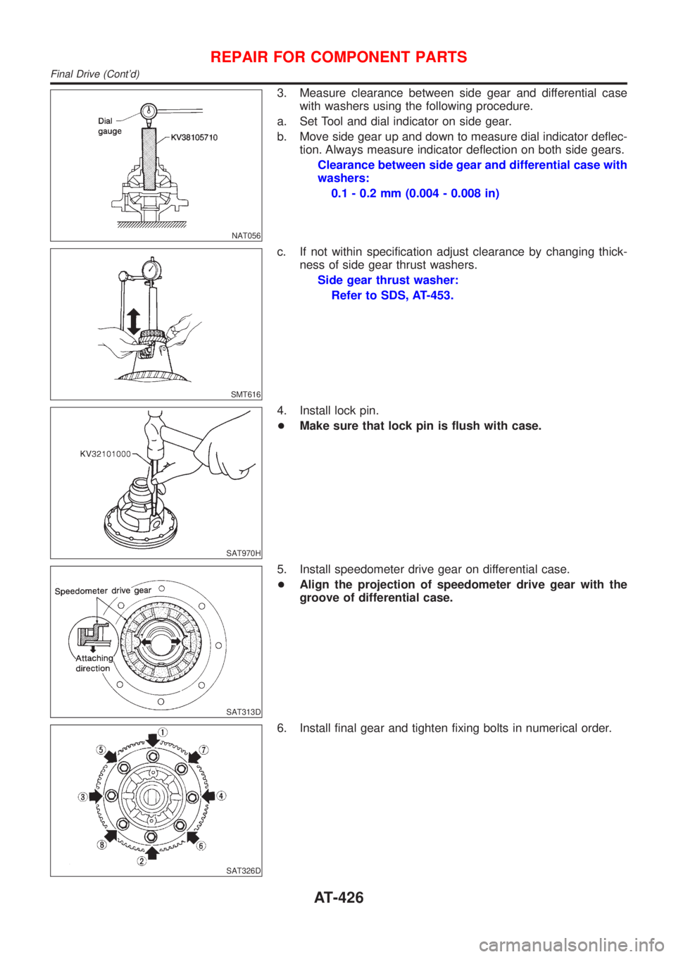
3. Measure clearance between side gear and differential case
with washers using the following procedure.
a. Set Tool and dial indicator on side gear.
b. Move side gear up and down to measure dial indicator deflec-
tion. Always measure indicator deflection on both side gears.
Clearance between side gear and differential case with
washers:
0.1 - 0.2 mm (0.004 - 0.008 in)
SMT616
c. If not within specification adjust clearance by changing thick-
ness of side gear thrust washers.
Side gear thrust washer:
Refer to SDS, AT-453.
SAT970H
4. Install lock pin.
+Make sure that lock pin is flush with case.
SAT313D
5. Install speedometer drive gear on differential case.
+Align the projection of speedometer drive gear with the
groove of differential case.
SAT326D
6. Install final gear and tighten fixing bolts in numerical order.
REPAIR FOR COMPONENT PARTS
Final Drive (Cont'd)
AT-426
Page 1699 of 2493
BRAKE SYSTEM
SECTION
BR
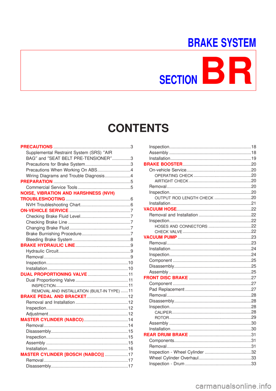
CONTENTS
PRECAUTIONS...............................................................3
Supplemental Restraint System (SRS)²AIR
BAG²and²SEAT BELT PRE-TENSIONER²...............3
Precautions for Brake System .....................................3
Precautions When Working On ABS ...........................4
Wiring Diagrams and Trouble Diagnosis .....................4
PREPARATION...............................................................5
Commercial Service Tools ...........................................5
NOISE, VIBRATION AND HARSHNESS (NVH)
TROUBLESHOOTING.....................................................6
NVH Troubleshooting Chart.........................................6
ON-VEHICLE SERVICE..................................................7
Checking Brake Fluid Level.........................................7
Checking Brake Line ...................................................7
Changing Brake Fluid ..................................................7
Brake Burnishing Procedure........................................7
Bleeding Brake System ...............................................8
BRAKE HYDRAULIC LINE.............................................9
Hydraulic Circuit...........................................................9
Removal .......................................................................9
Inspection...................................................................10
Installation ..................................................................10
DUAL PROPORTIONING VALVE................................. 11
Dual Proportioning Valve ........................................... 11
INSPECTION........................................................... 11
REMOVAL AND INSTALLATION (BUILT-IN TYPE)...... 11
BRAKE PEDAL AND BRACKET..................................12
Removal and Installation ...........................................12
Inspection...................................................................12
Adjustment .................................................................12
MASTER CYLINDER (NABCO)....................................14
Removal .....................................................................14
Disassembly...............................................................15
Inspection...................................................................15
Assembly ...................................................................15
Installation ..................................................................16
MASTER CYLINDER [BOSCH (NABCO)]...................17
Removal .....................................................................17
Disassembly...............................................................17Inspection...................................................................18
Assembly ...................................................................18
Installation ..................................................................19
BRAKE BOOSTER........................................................20
On-vehicle Service.....................................................20
OPERATING CHECK...............................................20
AIRTIGHT CHECK...................................................20
Removal .....................................................................20
Inspection...................................................................20
OUTPUT ROD LENGTH CHECK..............................20
Installation ..................................................................21
VACUUM HOSE.............................................................22
Removal and Installation ...........................................22
Inspection...................................................................22
HOSES AND CONNECTORS...................................22
CHECK VALVE........................................................22
VACUUM PUMP............................................................23
Removal .....................................................................23
Installation ..................................................................24
Inspection...................................................................24
Component ................................................................25
Disassembly...............................................................25
Assembly ...................................................................25
FRONT DISC BRAKE...................................................27
Component ................................................................27
Pad Replacement ......................................................27
Removal .....................................................................28
Disassembly...............................................................28
Inspection...................................................................28
CALIPER.................................................................28
ROTOR...................................................................29
Assembly ...................................................................30
Installation ..................................................................30
REAR DRUM BRAKE...................................................31
Components...............................................................31
Removal .....................................................................31
Inspection - Wheel Cylinder ......................................32
Wheel Cylinder Overhaul...........................................33
Inspection - Drum ......................................................33
Page 1702 of 2493
Precautions When Working On ABSNJBR0140+Use recommended tyres in combination with ABS.
+Please fit tyres or studded tyres, etc. with the same size.
+If different sizes of tyres, or tyres other than the ones rec-
ommended for use with the ABS, are fitted, stopping dis-
tance will increase and control and stability could deterio-
rate.
+When changing brake pads, please use Nissan genuine
parts.
+When fitting radios etc, do not position the radio itself,
antenna, or antenna cables within an area of about 100
mm (3.94 in) of the control unit.
+When doing any work that requires electro-welding, first
remove the control unit.
+Please take care when taking a power supply for the
audio, lamps etc., not to take this from any ABS-related
harness. (Please refer to the electrical wiring diagrams for
ABS-related harnesses)
Wiring Diagrams and Trouble DiagnosisNJBR0003When you read wiring diagrams, refer to the following:
+GI-12, ªHOW TO READ WIRING DIAGRAMSº
+EL-10, ªPOWER SUPPLY ROUTINGº
When you perform trouble diagnosis, refer to the following:
+GI-31, ªHOW TO FOLLOW TEST GROUPS IN TROUBLE DIAGNOSESº
+GI-21, ªHOW TO PERFORM EFFICIENT DIAGNOSIS FOR AN ELECTRICAL INCIDENTº
+On board self-diagnosis is available everywhere except for Europe.
PRECAUTIONS
Precautions When Working On ABS
BR-4
Page 1705 of 2493
SBR451D
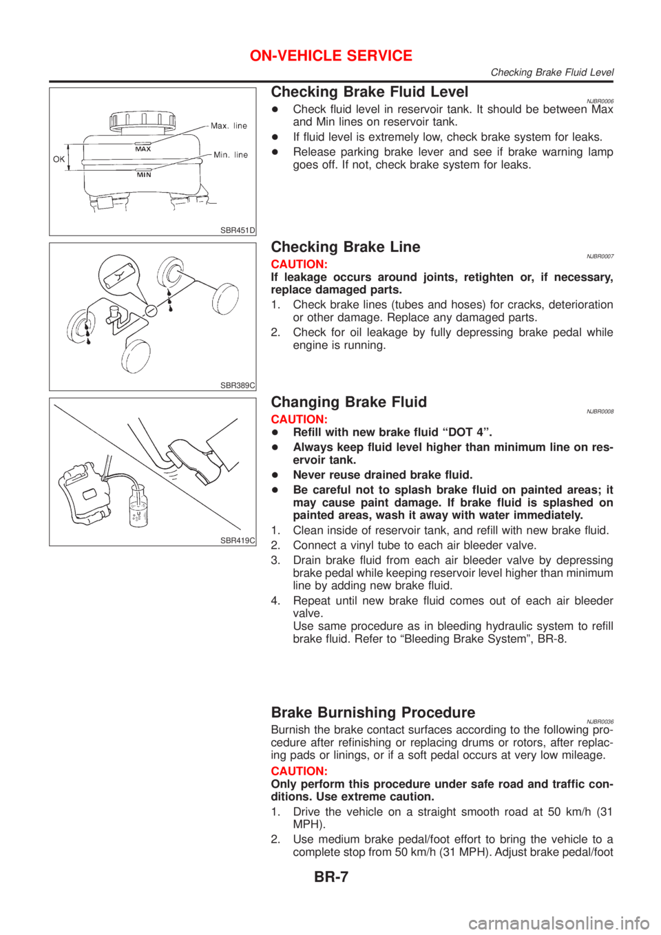
Checking Brake Fluid LevelNJBR0006+Check fluid level in reservoir tank. It should be between Max
and Min lines on reservoir tank.
+If fluid level is extremely low, check brake system for leaks.
+Release parking brake lever and see if brake warning lamp
goes off. If not, check brake system for leaks.
SBR389C
Checking Brake LineNJBR0007CAUTION:
If leakage occurs around joints, retighten or, if necessary,
replace damaged parts.
1. Check brake lines (tubes and hoses) for cracks, deterioration
or other damage. Replace any damaged parts.
2. Check for oil leakage by fully depressing brake pedal while
engine is running.
SBR419C
Changing Brake FluidNJBR0008CAUTION:
+Refill with new brake fluid ªDOT 4º.
+Always keep fluid level higher than minimum line on res-
ervoir tank.
+Never reuse drained brake fluid.
+Be careful not to splash brake fluid on painted areas; it
may cause paint damage. If brake fluid is splashed on
painted areas, wash it away with water immediately.
1. Clean inside of reservoir tank, and refill with new brake fluid.
2. Connect a vinyl tube to each air bleeder valve.
3. Drain brake fluid from each air bleeder valve by depressing
brake pedal while keeping reservoir level higher than minimum
line by adding new brake fluid.
4. Repeat until new brake fluid comes out of each air bleeder
valve.
Use same procedure as in bleeding hydraulic system to refill
brake fluid. Refer to ªBleeding Brake Systemº, BR-8.
Brake Burnishing ProcedureNJBR0036Burnish the brake contact surfaces according to the following pro-
cedure after refinishing or replacing drums or rotors, after replac-
ing pads or linings, or if a soft pedal occurs at very low mileage.
CAUTION:
Only perform this procedure under safe road and traffic con-
ditions. Use extreme caution.
1. Drive the vehicle on a straight smooth road at 50 km/h (31
MPH).
2. Use medium brake pedal/foot effort to bring the vehicle to a
complete stop from 50 km/h (31 MPH). Adjust brake pedal/foot
ON-VEHICLE SERVICE
Checking Brake Fluid Level
BR-7
Page 2066 of 2493
Heater & Cooling Unit (Heater Core)
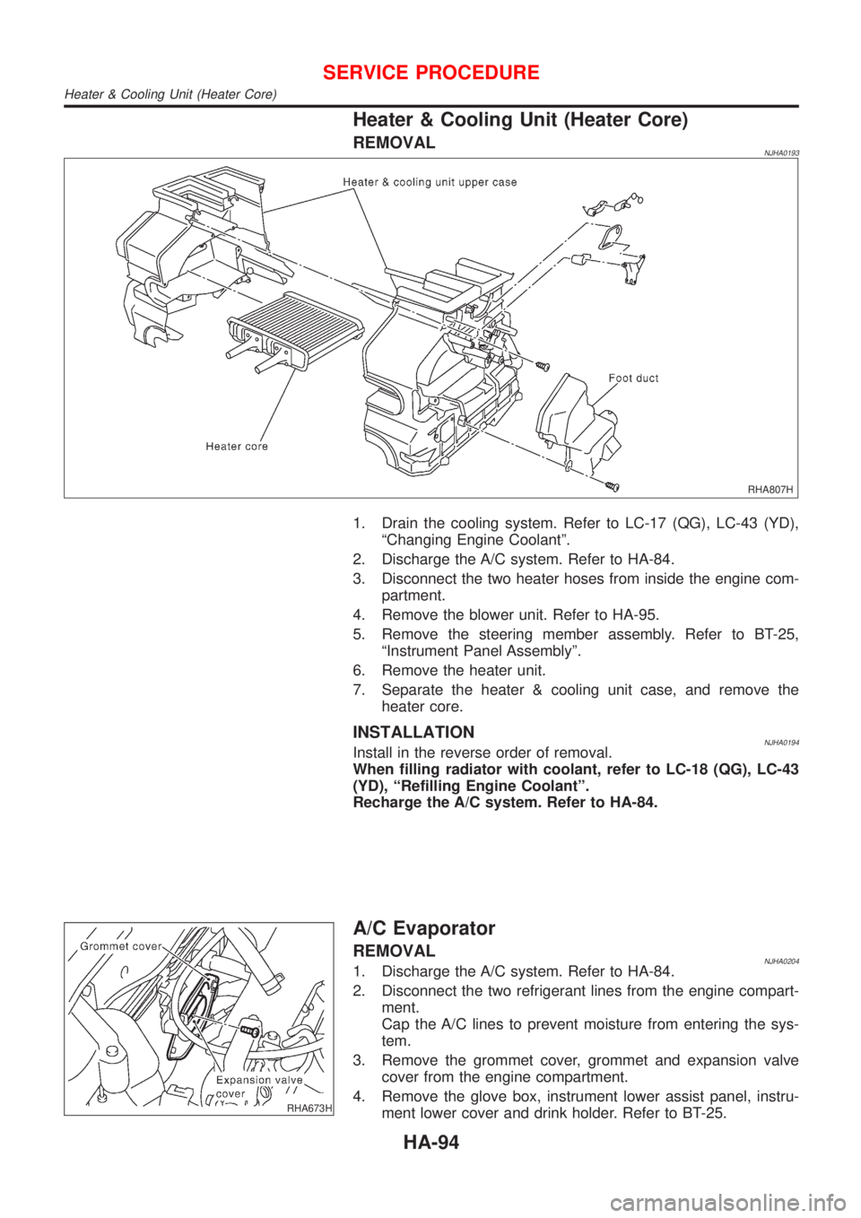
REMOVALNJHA0193
RHA807H
1. Drain the cooling system. Refer to LC-17 (QG), LC-43 (YD),
ªChanging Engine Coolantº.
2. Discharge the A/C system. Refer to HA-84.
3. Disconnect the two heater hoses from inside the engine com-
partment.
4. Remove the blower unit. Refer to HA-95.
5. Remove the steering member assembly. Refer to BT-25,
ªInstrument Panel Assemblyº.
6. Remove the heater unit.
7. Separate the heater & cooling unit case, and remove the
heater core.
INSTALLATIONNJHA0194Install in the reverse order of removal.
When filling radiator with coolant, refer to LC-18 (QG), LC-43
(YD), ªRefilling Engine Coolantº.
Recharge the A/C system. Refer to HA-84.
RHA673H
A/C Evaporator
REMOVALNJHA02041. Discharge the A/C system. Refer to HA-84.
2. Disconnect the two refrigerant lines from the engine compart-
ment.
Cap the A/C lines to prevent moisture from entering the sys-
tem.
3. Remove the grommet cover, grommet and expansion valve
cover from the engine compartment.
4. Remove the glove box, instrument lower assist panel, instru-
ment lower cover and drink holder. Refer to BT-25.
SERVICE PROCEDURE
Heater & Cooling Unit (Heater Core)
HA-94
Page 2430 of 2493
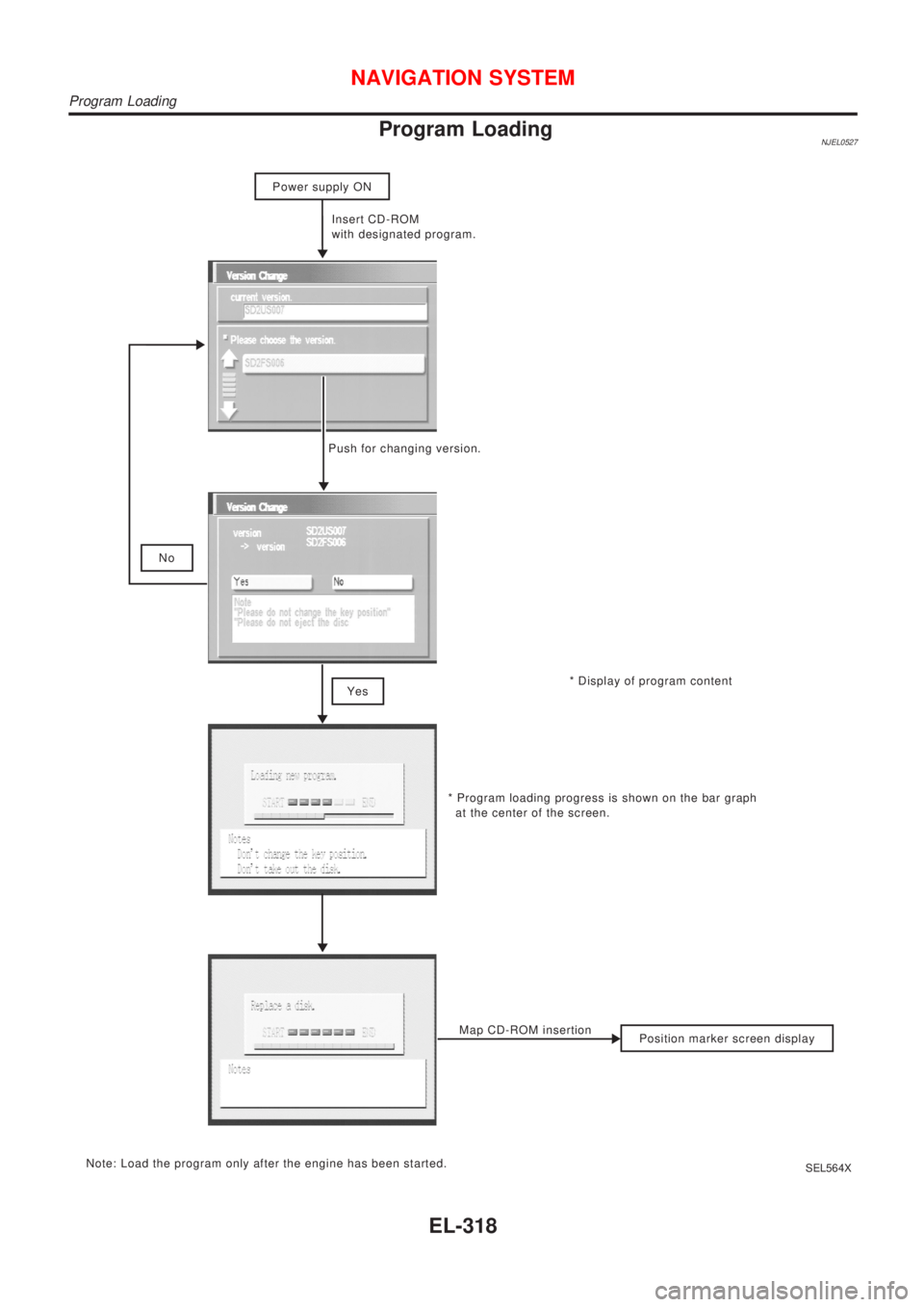
Program LoadingNJEL0527
* Display of program content Insert CD-ROM
with designated program.
Position marker screen display No
* Program loading progress is shown on the bar graph
at the center of the screen.
Note: Load the program only after the engine has been started.Map CD-ROM insertion
Power supply ON
Push for changing version.
Yes
SEL564X
NAVIGATION SYSTEM
Program Loading
EL-318