2001 NISSAN ALMERA N16 Changing
[x] Cancel search: ChangingPage 999 of 2493
ACCELERATOR CONTROL, FUEL &
EXHAUST SYSTEMS
SECTION
FE
CONTENTS
QG
PREPARATION...............................................................2
Special Service Tools ..................................................2
Commercial Service Tools ...........................................2
ACCELERATOR CONTROL SYSTEM...........................3
Removal and Installation .............................................3
Adjusting Accelerator Wire ..........................................3
FUEL SYSTEM................................................................5
Checking Fuel Lines ....................................................5
Removal and Installation .............................................5
Fuel Tank .....................................................................6
REMOVAL.................................................................6
INSTALLATION..........................................................8
Fuel Pump, Fuel Level Sensor Unit and Fuel
Filter .............................................................................9
REMOVAL.................................................................9
INSTALLATION........................................................10
EXHAUST SYSTEM...................................................... 11
Checking Exhaust System......................................... 11
Removal and Installation ........................................... 11
YD
PREPARATION.............................................................14
Special Service Tool ..................................................14Commercial Service Tool ...........................................14
ACCELERATOR CONTROL SYSTEM.........................15
Removal and Installation ...........................................15
Inspection...................................................................15
FUEL SYSTEM..............................................................16
Checking Fuel Lines ..................................................16
Water Draining from Fuel Filter .................................16
DRAINING WATER..................................................16
FUEL FILTER CHECK..............................................16
Changing Fuel Filter ..................................................16
REMOVAL...............................................................16
INSTALLATION........................................................16
Bleeding Fuel Filter....................................................17
Checking Priming Pump ............................................17
Removal and Installation ...........................................17
Fuel Tank ...................................................................18
REMOVAL...............................................................20
INSTALLATION........................................................23
Fuel Level Sensor Unit ..............................................24
REMOVAL...............................................................25
INSTALLATION........................................................26
EXHAUST SYSTEM......................................................27
Checking Exhaust System.........................................27
Removal and Installation ...........................................27
Page 1014 of 2493
SMA803A
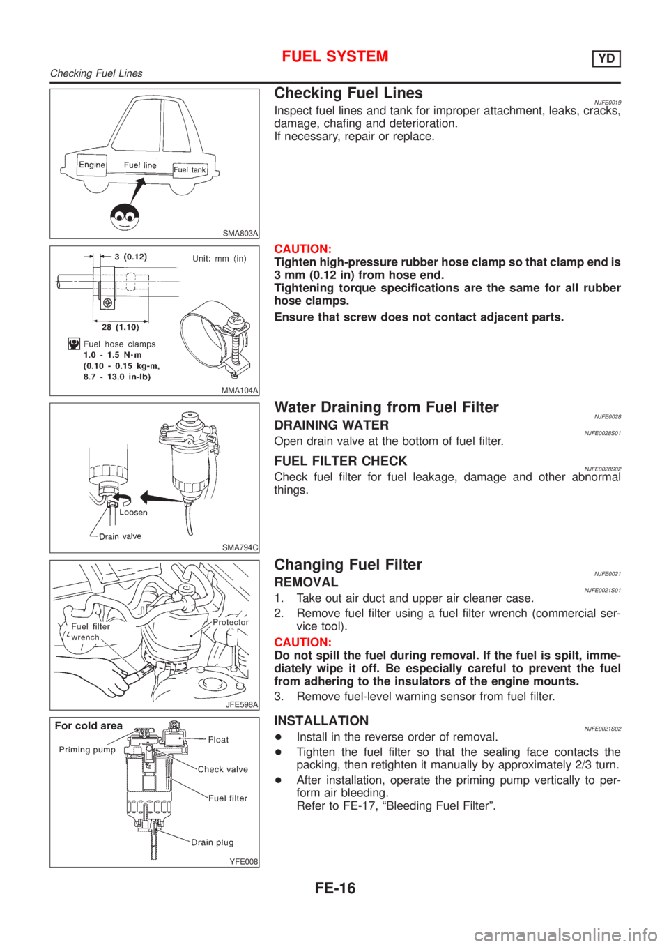
Checking Fuel LinesNJFE0019Inspect fuel lines and tank for improper attachment, leaks, cracks,
damage, chafing and deterioration.
If necessary, repair or replace.
MMA104A
CAUTION:
Tighten high-pressure rubber hose clamp so that clamp end is
3 mm (0.12 in) from hose end.
Tightening torque specifications are the same for all rubber
hose clamps.
Ensure that screw does not contact adjacent parts.
SMA794C
Water Draining from Fuel FilterNJFE0028DRAINING WATERNJFE0028S01Open drain valve at the bottom of fuel filter.
FUEL FILTER CHECKNJFE0028S02Check fuel filter for fuel leakage, damage and other abnormal
things.
JFE598A
Changing Fuel FilterNJFE0021REMOVALNJFE0021S011. Take out air duct and upper air cleaner case.
2. Remove fuel filter using a fuel filter wrench (commercial ser-
vice tool).
CAUTION:
Do not spill the fuel during removal. If the fuel is spilt, imme-
diately wipe it off. Be especially careful to prevent the fuel
from adhering to the insulators of the engine mounts.
3. Remove fuel-level warning sensor from fuel filter.
YFE008
INSTALLATIONNJFE0021S02+Install in the reverse order of removal.
+Tighten the fuel filter so that the sealing face contacts the
packing, then retighten it manually by approximately 2/3 turn.
+After installation, operate the priming pump vertically to per-
form air bleeding.
Refer to FE-17, ªBleeding Fuel Filterº.
FUEL SYSTEMYD
Checking Fuel Lines
FE-16
Page 1051 of 2493
MANUAL TRANSAXLE
SECTION
MT
CONTENTS
RS5F30A
PREPARATION...............................................................4
Special Service Tools ..................................................4
Commercial Service Tools ...........................................6
RS5F70A
PREPARATION...............................................................7
Special Service Tools ..................................................7
Commercial Service Tools ...........................................9
RS5F50A
PREPARATION.............................................................10
Special Service Tools ................................................10
Commercial Service Tools .........................................12
NOISE, VIBRATION AND HARSHNESS (NVH)
TROUBLESHOOTING...................................................13
NVH Troubleshooting Chart.......................................13
MANUAL TRANSAXLE.............................................13
RS5F30A, RS5F70A
M/T OIL..........................................................................14
Changing M/T Oil.......................................................14
Checking ....................................................................14
OIL LEAK AND OIL LEVEL.......................................14
RS5F50A
M/T OIL..........................................................................15
Changing M/T Oil.......................................................15
Checking ....................................................................15
OIL LEAK AND OIL LEVEL.......................................15
DESCRIPTION...............................................................16
Cross-sectional View - RS5F30A ..............................16Cross-sectional View - RS5F70A ..............................17
Cross-sectional View - RS5F50A ..............................18
DOUBLE-CONE SYNCHRONIZER............................19
ON-VEHICLE SERVICE................................................20
Replacing Oil Seal .....................................................20
DIFFERENTIAL OIL SEAL........................................20
STRIKING ROD OIL SEAL.......................................21
Position Switch Check ...............................................21
BACK-UP LAMP SWITCH........................................21
PNP SWITCH..........................................................22
BACK-UP LAMP SWITCH AND PNP SWITCH...........22
RS5F30A, RS5F70A
REMOVAL AND INSTALLATION.................................23
Removal .....................................................................23
Installation ..................................................................24
MODEL QG15DE ENGINE.......................................24
MODEL QG18DE ENGINE.......................................25
RS5F50A
REMOVAL AND INSTALLATION.................................26
Removal .....................................................................26
Installation ..................................................................28
MODEL YD ENGINE................................................28
TRANSAXLE GEAR CONTROL...................................29
Components...............................................................29
RS5F30A
OVERHAUL...................................................................30
Case Components .....................................................30
Gear Components .....................................................31
Shift Control Components .........................................32
DISASSEMBLY..............................................................33
REPAIR FOR COMPONENT PARTS...........................36
Input Shaft and Gears ...............................................36
DISASSEMBLY........................................................36
Page 1064 of 2493
SMA145AA
SMT512C
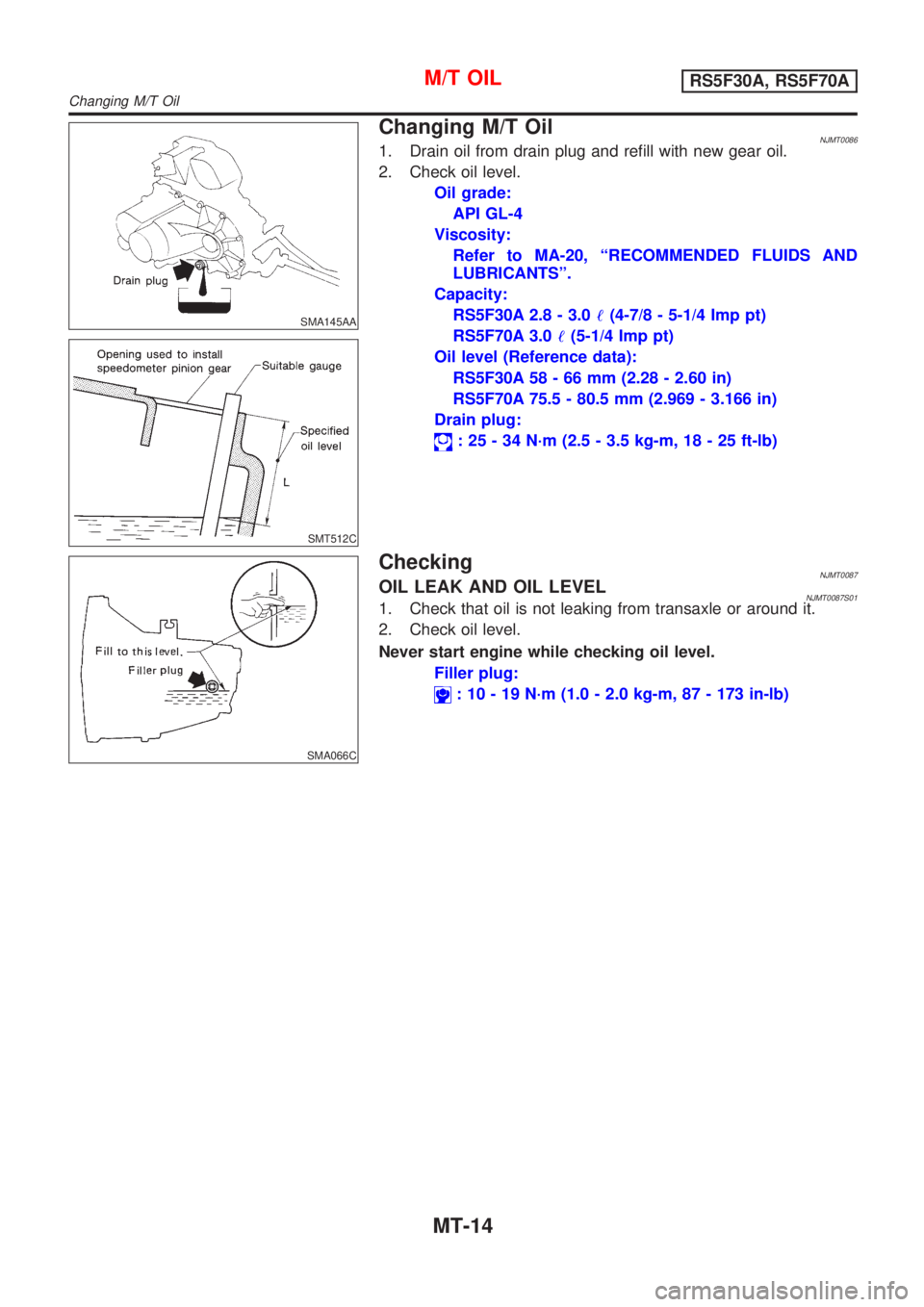
Changing M/T OilNJMT00861. Drain oil from drain plug and refill with new gear oil.
2. Check oil level.
Oil grade:
API GL-4
Viscosity:
Refer to MA-20, ªRECOMMENDED FLUIDS AND
LUBRICANTSº.
Capacity:
RS5F30A 2.8 - 3.0!(4-7/8 - 5-1/4 Imp pt)
RS5F70A 3.0!(5-1/4 Imp pt)
Oil level (Reference data):
RS5F30A 58 - 66 mm (2.28 - 2.60 in)
RS5F70A 75.5 - 80.5 mm (2.969 - 3.166 in)
Drain plug:
: 25 - 34 N´m (2.5 - 3.5 kg-m, 18 - 25 ft-lb)
SMA066C
CheckingNJMT0087OIL LEAK AND OIL LEVELNJMT0087S011. Check that oil is not leaking from transaxle or around it.
2. Check oil level.
Never start engine while checking oil level.
Filler plug:
: 10 - 19 N´m (1.0 - 2.0 kg-m, 87 - 173 in-lb)
M/T OILRS5F30A, RS5F70A
Changing M/T Oil
MT-14
Page 1065 of 2493
SMA067C
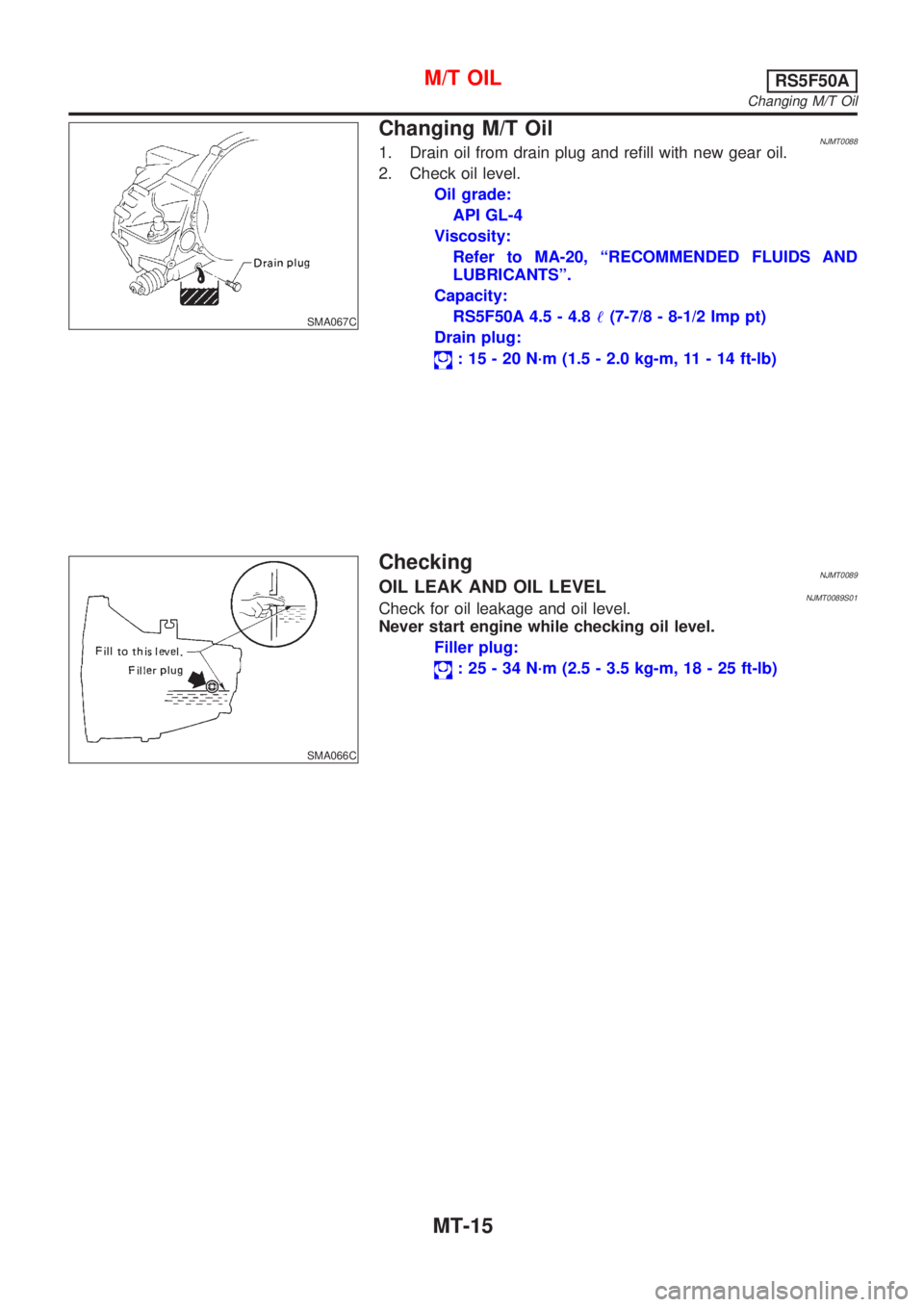
Changing M/T OilNJMT00881. Drain oil from drain plug and refill with new gear oil.
2. Check oil level.
Oil grade:
API GL-4
Viscosity:
Refer to MA-20, ªRECOMMENDED FLUIDS AND
LUBRICANTSº.
Capacity:
RS5F50A 4.5 - 4.8!(7-7/8 - 8-1/2 Imp pt)
Drain plug:
: 15 - 20 N´m (1.5 - 2.0 kg-m, 11 - 14 ft-lb)
SMA066C
CheckingNJMT0089OIL LEAK AND OIL LEVELNJMT0089S01Check for oil leakage and oil level.
Never start engine while checking oil level.
Filler plug:
: 25 - 34 N´m (2.5 - 3.5 kg-m, 18 - 25 ft-lb)
M/T OILRS5F50A
Changing M/T Oil
MT-15
Page 1095 of 2493
SMT610AB
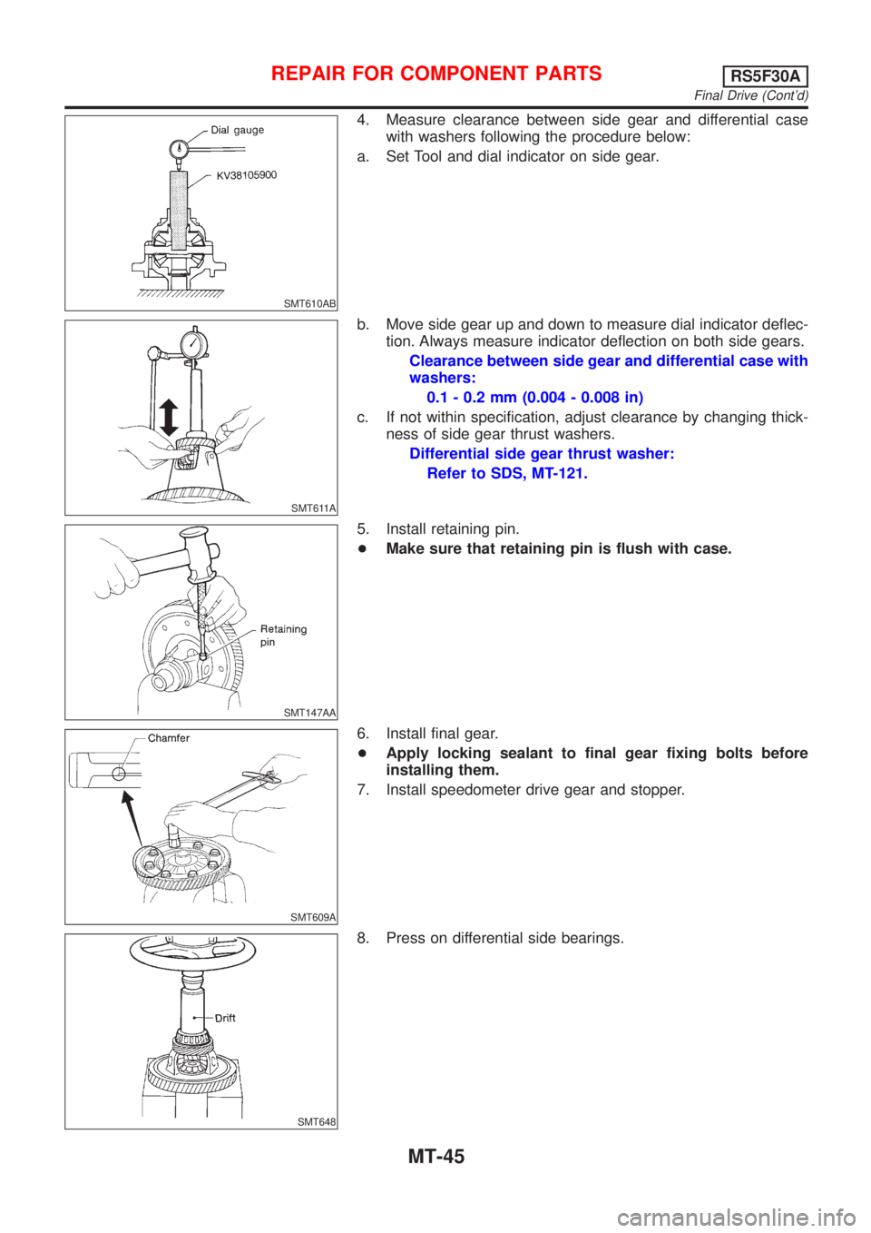
4. Measure clearance between side gear and differential case
with washers following the procedure below:
a. Set Tool and dial indicator on side gear.
SMT611A
b. Move side gear up and down to measure dial indicator deflec-
tion. Always measure indicator deflection on both side gears.
Clearance between side gear and differential case with
washers:
0.1 - 0.2 mm (0.004 - 0.008 in)
c. If not within specification, adjust clearance by changing thick-
ness of side gear thrust washers.
Differential side gear thrust washer:
Refer to SDS, MT-121.
SMT147AA
5. Install retaining pin.
+Make sure that retaining pin is flush with case.
SMT609A
6. Install final gear.
+Apply locking sealant to final gear fixing bolts before
installing them.
7. Install speedometer drive gear and stopper.
SMT648
8. Press on differential side bearings.
REPAIR FOR COMPONENT PARTSRS5F30A
Final Drive (Cont'd)
MT-45
Page 1117 of 2493
SMT695D
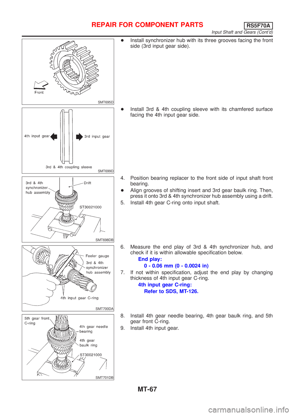
+Install synchronizer hub with its three grooves facing the front
side (3rd input gear side).
SMT699D
+Install 3rd & 4th coupling sleeve with its chamfered surface
facing the 4th input gear side.
SMT698DB
4. Position bearing replacer to the front side of input shaft front
bearing.
+Align grooves of shifting insert and 3rd gear baulk ring. Then,
press it onto 3rd & 4th synchronizer hub assembly using a drift.
5. Install 4th gear C-ring onto input shaft.
SMT700DA
6. Measure the end play of 3rd & 4th synchronizer hub, and
check if it is within allowable specification below.
End play:
0 - 0.06 mm (0 - 0.0024 in)
7. If not within specification, adjust the end play by changing
thickness of 4th input gear C-ring.
4th input gear C-ring:
Refer to SDS, MT-126.
SMT701DB
8. Install 4th gear needle bearing, 4th gear baulk ring, and 5th
gear front C-ring.
9. Install 4th input gear.
REPAIR FOR COMPONENT PARTSRS5F70A
Input Shaft and Gears (Cont'd)
MT-67
Page 1118 of 2493
SMT703D
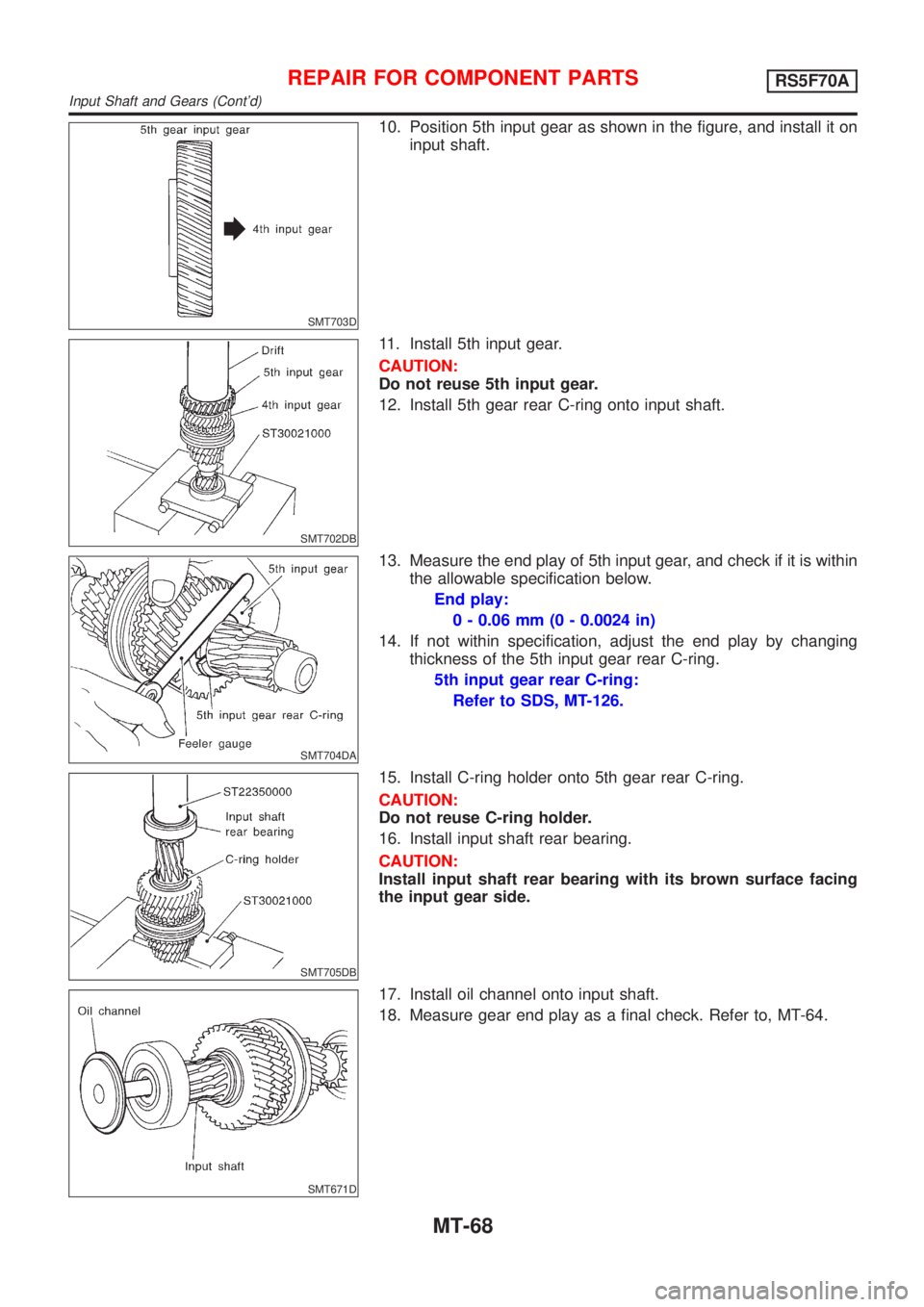
10. Position 5th input gear as shown in the figure, and install it on
input shaft.
SMT702DB
11. Install 5th input gear.
CAUTION:
Do not reuse 5th input gear.
12. Install 5th gear rear C-ring onto input shaft.
SMT704DA
13. Measure the end play of 5th input gear, and check if it is within
the allowable specification below.
End play:
0 - 0.06 mm (0 - 0.0024 in)
14. If not within specification, adjust the end play by changing
thickness of the 5th input gear rear C-ring.
5th input gear rear C-ring:
Refer to SDS, MT-126.
SMT705DB
15. Install C-ring holder onto 5th gear rear C-ring.
CAUTION:
Do not reuse C-ring holder.
16. Install input shaft rear bearing.
CAUTION:
Install input shaft rear bearing with its brown surface facing
the input gear side.
SMT671D
17. Install oil channel onto input shaft.
18. Measure gear end play as a final check. Refer to, MT-64.
REPAIR FOR COMPONENT PARTSRS5F70A
Input Shaft and Gears (Cont'd)
MT-68