2001 NISSAN ALMERA N16 check engine
[x] Cancel search: check enginePage 1016 of 2493
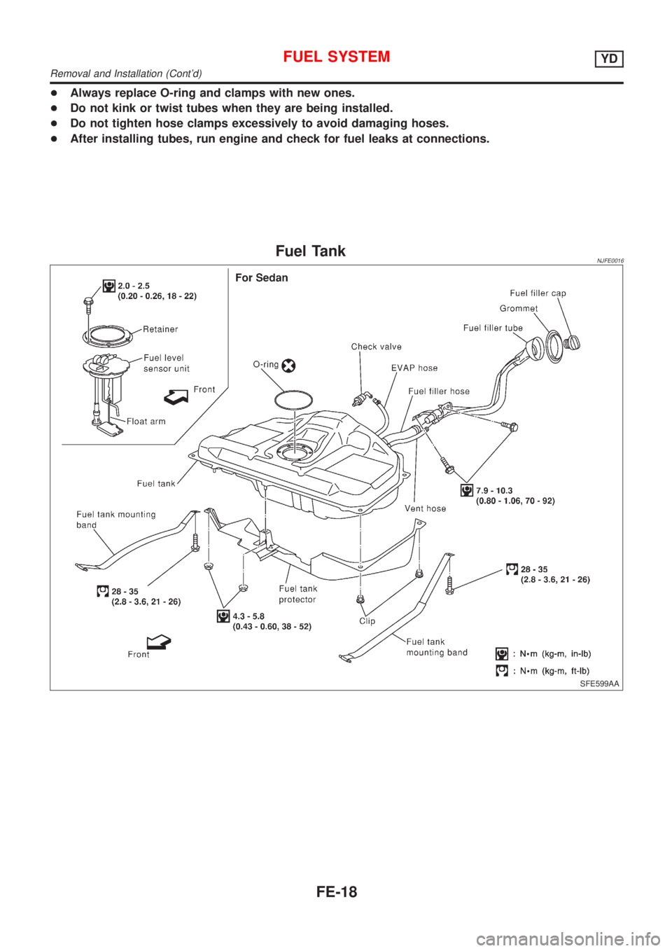
+Always replace O-ring and clamps with new ones.
+Do not kink or twist tubes when they are being installed.
+Do not tighten hose clamps excessively to avoid damaging hoses.
+After installing tubes, run engine and check for fuel leaks at connections.
Fuel TankNJFE0016
SFE599AA
FUEL SYSTEMYD
Removal and Installation (Cont'd)
FE-18
Page 1025 of 2493
SMA211A
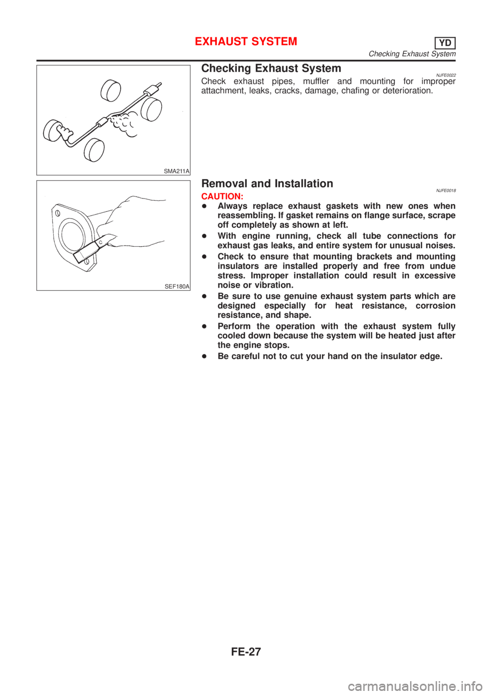
Checking Exhaust SystemNJFE0022Check exhaust pipes, muffler and mounting for improper
attachment, leaks, cracks, damage, chafing or deterioration.
SEF180A
Removal and InstallationNJFE0018CAUTION:
+Always replace exhaust gaskets with new ones when
reassembling. If gasket remains on flange surface, scrape
off completely as shown at left.
+With engine running, check all tube connections for
exhaust gas leaks, and entire system for unusual noises.
+Check to ensure that mounting brackets and mounting
insulators are installed properly and free from undue
stress. Improper installation could result in excessive
noise or vibration.
+Be sure to use genuine exhaust system parts which are
designed especially for heat resistance, corrosion
resistance, and shape.
+Perform the operation with the exhaust system fully
cooled down because the system will be heated just after
the engine stops.
+Be careful not to cut your hand on the insulator edge.
EXHAUST SYSTEMYD
Checking Exhaust System
FE-27
Page 1049 of 2493
SCL466-C
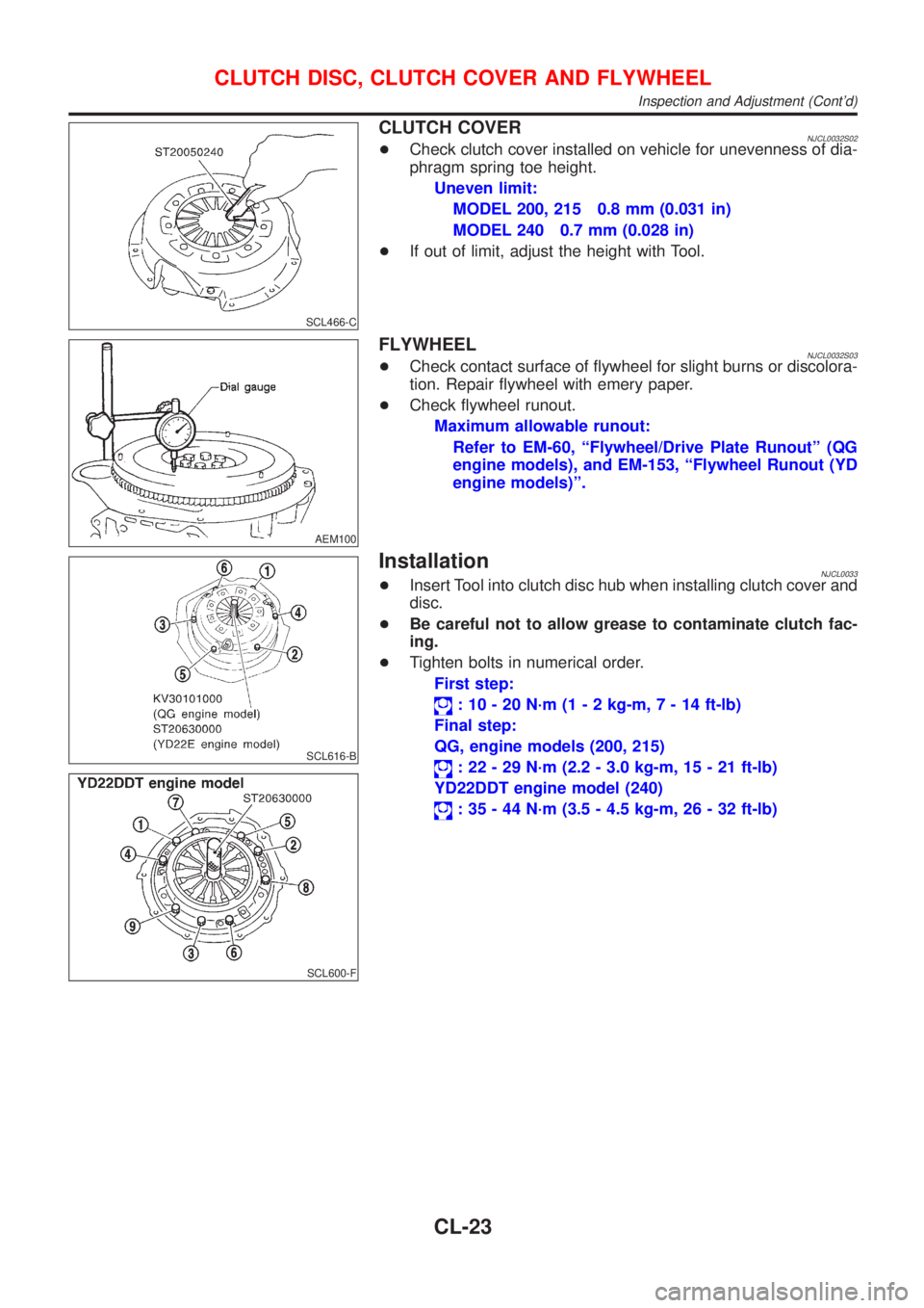
CLUTCH COVERNJCL0032S02+Check clutch cover installed on vehicle for unevenness of dia-
phragm spring toe height.
Uneven limit:
MODEL 200, 215 0.8 mm (0.031 in)
MODEL 240 0.7 mm (0.028 in)
+If out of limit, adjust the height with Tool.
AEM100
FLYWHEELNJCL0032S03+Check contact surface of flywheel for slight burns or discolora-
tion. Repair flywheel with emery paper.
+Check flywheel runout.
Maximum allowable runout:
Refer to EM-60, ªFlywheel/Drive Plate Runoutº (QG
engine models), and EM-153, ªFlywheel Runout (YD
engine models)º.
SCL616-B
SCL600-F
InstallationNJCL0033+Insert Tool into clutch disc hub when installing clutch cover and
disc.
+Be careful not to allow grease to contaminate clutch fac-
ing.
+Tighten bolts in numerical order.
First step:
: 10 - 20 N´m (1 - 2 kg-m,7-14ft-lb)
Final step:
QG, engine models (200, 215)
: 22 - 29 N´m (2.2 - 3.0 kg-m, 15 - 21 ft-lb)
YD22DDT engine model (240)
: 35 - 44 N´m (3.5 - 4.5 kg-m, 26 - 32 ft-lb)
CLUTCH DISC, CLUTCH COVER AND FLYWHEEL
Inspection and Adjustment (Cont'd)
CL-23
Page 1050 of 2493
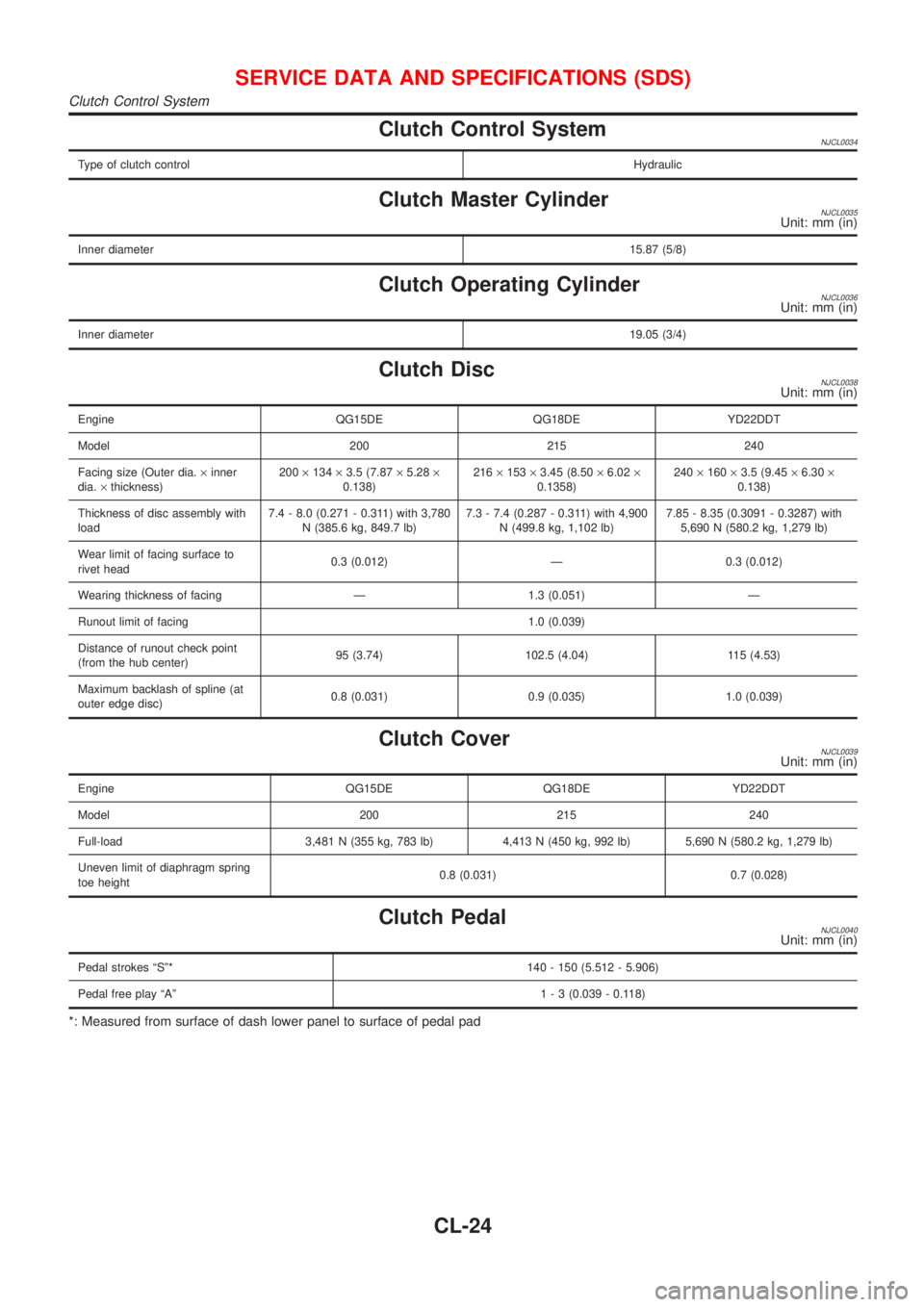
Clutch Control SystemNJCL0034
Type of clutch controlHydraulic
Clutch Master CylinderNJCL0035Unit: mm (in)
Inner diameter15.87 (5/8)
Clutch Operating CylinderNJCL0036Unit: mm (in)
Inner diameter19.05 (3/4)
Clutch DiscNJCL0038Unit: mm (in)
Engine QG15DE QG18DE YD22DDT
Model 200 215 240
Facing size (Outer dia.´inner
dia.´thickness)200´134´3.5 (7.87´5.28´
0.138)216´153´3.45 (8.50´6.02´
0.1358)240´160´3.5 (9.45´6.30´
0.138)
Thickness of disc assembly with
load7.4 - 8.0 (0.271 - 0.311) with 3,780
N (385.6 kg, 849.7 lb)7.3 - 7.4 (0.287 - 0.311) with 4,900
N (499.8 kg, 1,102 lb)7.85 - 8.35 (0.3091 - 0.3287) with
5,690 N (580.2 kg, 1,279 lb)
Wear limit of facing surface to
rivet head0.3 (0.012) Ð 0.3 (0.012)
Wearing thickness of facing Ð 1.3 (0.051) Ð
Runout limit of facing 1.0 (0.039)
Distance of runout check point
(from the hub center)95 (3.74) 102.5 (4.04) 115 (4.53)
Maximum backlash of spline (at
outer edge disc)0.8 (0.031) 0.9 (0.035) 1.0 (0.039)
Clutch CoverNJCL0039Unit: mm (in)
Engine QG15DE QG18DE YD22DDT
Model 200 215 240
Full-load 3,481 N (355 kg, 783 lb) 4,413 N (450 kg, 992 lb) 5,690 N (580.2 kg, 1,279 lb)
Uneven limit of diaphragm spring
toe height0.8 (0.031) 0.7 (0.028)
Clutch PedalNJCL0040Unit: mm (in)
Pedal strokes ªSº* 140 - 150 (5.512 - 5.906)
Pedal free play ªAº1 - 3 (0.039 - 0.118)
*: Measured from surface of dash lower panel to surface of pedal pad
SERVICE DATA AND SPECIFICATIONS (SDS)
Clutch Control System
CL-24
Page 1051 of 2493
MANUAL TRANSAXLE
SECTION
MT
CONTENTS
RS5F30A
PREPARATION...............................................................4
Special Service Tools ..................................................4
Commercial Service Tools ...........................................6
RS5F70A
PREPARATION...............................................................7
Special Service Tools ..................................................7
Commercial Service Tools ...........................................9
RS5F50A
PREPARATION.............................................................10
Special Service Tools ................................................10
Commercial Service Tools .........................................12
NOISE, VIBRATION AND HARSHNESS (NVH)
TROUBLESHOOTING...................................................13
NVH Troubleshooting Chart.......................................13
MANUAL TRANSAXLE.............................................13
RS5F30A, RS5F70A
M/T OIL..........................................................................14
Changing M/T Oil.......................................................14
Checking ....................................................................14
OIL LEAK AND OIL LEVEL.......................................14
RS5F50A
M/T OIL..........................................................................15
Changing M/T Oil.......................................................15
Checking ....................................................................15
OIL LEAK AND OIL LEVEL.......................................15
DESCRIPTION...............................................................16
Cross-sectional View - RS5F30A ..............................16Cross-sectional View - RS5F70A ..............................17
Cross-sectional View - RS5F50A ..............................18
DOUBLE-CONE SYNCHRONIZER............................19
ON-VEHICLE SERVICE................................................20
Replacing Oil Seal .....................................................20
DIFFERENTIAL OIL SEAL........................................20
STRIKING ROD OIL SEAL.......................................21
Position Switch Check ...............................................21
BACK-UP LAMP SWITCH........................................21
PNP SWITCH..........................................................22
BACK-UP LAMP SWITCH AND PNP SWITCH...........22
RS5F30A, RS5F70A
REMOVAL AND INSTALLATION.................................23
Removal .....................................................................23
Installation ..................................................................24
MODEL QG15DE ENGINE.......................................24
MODEL QG18DE ENGINE.......................................25
RS5F50A
REMOVAL AND INSTALLATION.................................26
Removal .....................................................................26
Installation ..................................................................28
MODEL YD ENGINE................................................28
TRANSAXLE GEAR CONTROL...................................29
Components...............................................................29
RS5F30A
OVERHAUL...................................................................30
Case Components .....................................................30
Gear Components .....................................................31
Shift Control Components .........................................32
DISASSEMBLY..............................................................33
REPAIR FOR COMPONENT PARTS...........................36
Input Shaft and Gears ...............................................36
DISASSEMBLY........................................................36
Page 1064 of 2493
SMA145AA
SMT512C
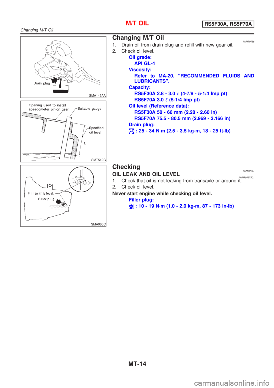
Changing M/T OilNJMT00861. Drain oil from drain plug and refill with new gear oil.
2. Check oil level.
Oil grade:
API GL-4
Viscosity:
Refer to MA-20, ªRECOMMENDED FLUIDS AND
LUBRICANTSº.
Capacity:
RS5F30A 2.8 - 3.0!(4-7/8 - 5-1/4 Imp pt)
RS5F70A 3.0!(5-1/4 Imp pt)
Oil level (Reference data):
RS5F30A 58 - 66 mm (2.28 - 2.60 in)
RS5F70A 75.5 - 80.5 mm (2.969 - 3.166 in)
Drain plug:
: 25 - 34 N´m (2.5 - 3.5 kg-m, 18 - 25 ft-lb)
SMA066C
CheckingNJMT0087OIL LEAK AND OIL LEVELNJMT0087S011. Check that oil is not leaking from transaxle or around it.
2. Check oil level.
Never start engine while checking oil level.
Filler plug:
: 10 - 19 N´m (1.0 - 2.0 kg-m, 87 - 173 in-lb)
M/T OILRS5F30A, RS5F70A
Changing M/T Oil
MT-14
Page 1065 of 2493
SMA067C
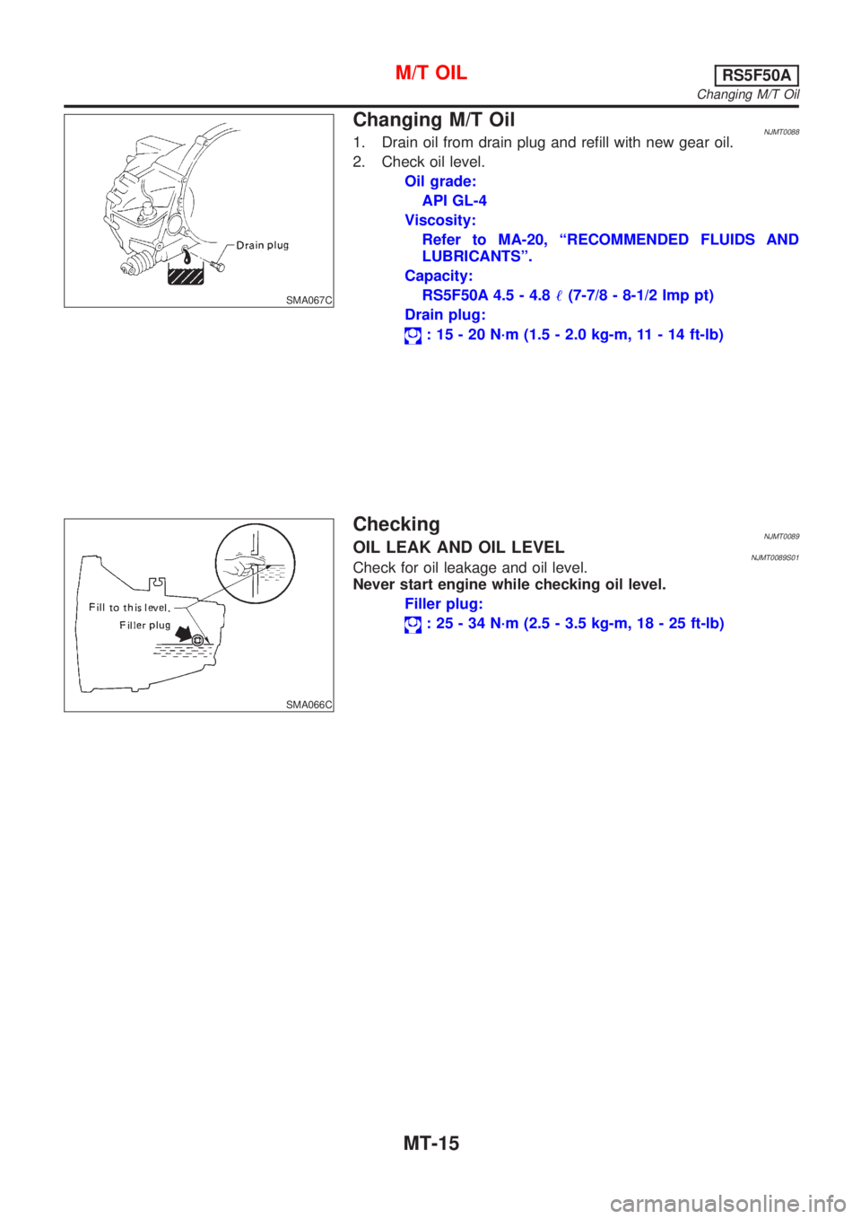
Changing M/T OilNJMT00881. Drain oil from drain plug and refill with new gear oil.
2. Check oil level.
Oil grade:
API GL-4
Viscosity:
Refer to MA-20, ªRECOMMENDED FLUIDS AND
LUBRICANTSº.
Capacity:
RS5F50A 4.5 - 4.8!(7-7/8 - 8-1/2 Imp pt)
Drain plug:
: 15 - 20 N´m (1.5 - 2.0 kg-m, 11 - 14 ft-lb)
SMA066C
CheckingNJMT0089OIL LEAK AND OIL LEVELNJMT0089S01Check for oil leakage and oil level.
Never start engine while checking oil level.
Filler plug:
: 25 - 34 N´m (2.5 - 3.5 kg-m, 18 - 25 ft-lb)
M/T OILRS5F50A
Changing M/T Oil
MT-15
Page 1187 of 2493
AUTOMATIC TRANSAXLE
SECTION
AT
CONTENTS
EURO-OBD
TROUBLE DIAGNOSIS - INDEX....................................5
Alphabetical & P No. Index for DTC ...........................5
PRECAUTIONS...............................................................7
Supplemental Restraint System (SRS)²AIR
BAG²and²SEAT BELT PRE-TENSIONER²...............7
Precautions for On Board Diagnostic (EURO-
OBD) System of A/T and Engine - Euro-OBD - ..........7
Precautions ..................................................................7
Service Notice or Precautions .....................................9
Wiring Diagrams and Trouble Diagnosis ...................10
PREPARATION............................................................. 11
Special Service Tools ................................................ 11
Commercial Service Tools .........................................13
A/T FLUID......................................................................15
Checking A/T Fluid ....................................................15
Changing A/T Fluid ....................................................15
OVERALL SYSTEM......................................................16
A/T Electrical Parts Location .....................................16
Circuit Diagram ..........................................................17
Cross-sectional View - ...............................................18
Hydraulic Control Circuit ............................................19
Shift Mechanism ........................................................20
Control System ..........................................................29
Control Mechanism ....................................................30
Control Valve .............................................................35
EXCEPT FOR EURO-OBD
ON BOARD DIAGNOSTIC SYSTEM............................37
CONSULT-II ...............................................................37
Diagnostic Procedure Without CONSULT-II ..............42
EURO-OBD
ON BOARD DIAGNOSTIC SYSTEM
DESCRIPTION...............................................................48Introduction ................................................................48
EURO-OBD Function for A/T System .......................48
One or Two Trip Detection Logic of EURO-OBD ......48
EURO-OBD Diagnostic Trouble Code (DTC)............48
Malfunction Indicator (MI) ..........................................52
CONSULT-II ...............................................................52
Diagnostic Procedure Without CONSULT-II ..............61
EXCEPT FOR EURO-OBD
TROUBLE DIAGNOSIS -...............................................67
Introduction ................................................................67
Work Flow ..................................................................71
EURO-OBD
TROUBLE DIAGNOSIS - INTRODUCTION..................72
Introduction ................................................................72
Work Flow ..................................................................76
TROUBLE DIAGNOSIS - BASIC INSPECTION...........78
A/T Fluid Check .........................................................78
Stall Test ....................................................................78
Line Pressure Test .....................................................82
Road Test...................................................................83
TROUBLE DIAGNOSIS - GENERAL
DESCRIPTION.............................................................103
Symptom Chart ........................................................103
TCM Terminals and Reference Value...................... 116
TROUBLE DIAGNOSIS FOR POWER SUPPLY........121
Wiring Diagram - AT - MAIN ....................................121
Diagnostic Procedure ..............................................122
EXCEPT FOR EURO-OBD
VEHICLE SPEED SENSOR.A/T..................................124
Description ...............................................................124
Wiring Diagram - AT - VSSA/T ................................126
Diagnostic Procedure ..............................................127