Page 1284 of 2493
3 CHECK SHIFT UP (D2TO D3)
Does A/T shift from D2to D3at the specified speed?
Read gear position, throttle position and vehicle speed.
Specified speed when shifting from D
2to D3:
Refer to Shift schedule, AT-449.
SAT960I
YesorNo
Ye s©GO TO 4.
No©Go to ª10. A/T Does Not Shift: D
2®D3º, AT-309. Continue ROAD TEST.
4 CHECK SHIFT UP (D3TO D4) AND ENGINE BRAKE
Release accelerator pedal after shifting from D2to D3.
Does A/T shift from D
3to D4and does vehicle decelerate by engine brake?
Read gear position, throttle position and vehicle speed.
SAT405H
YesorNo
Ye s©1. Stop vehicle.
2. Go to ªCruise test Ð Part 3º, AT-99.
No©Go to ª11. A/T Does Not Shift: D
3®D4º, AT-312. Continue ROAD TEST.
TROUBLE DIAGNOSIS Ð BASIC INSPECTION
Road Test (Cont'd)
AT-98
Page 1286 of 2493
2 CHECK ENGINE BRAKE
Does vehicle decelerate by engine brake?
SAT776BA
YesorNo
Ye s©GO TO 3.
No©Go to ª15. Engine Speed Does Not Return To Idle (Light Braking D
4®D3)º, AT-320.
Continue ROAD TEST.
3 CHECK SHIFT DOWN (D3TO D2)
1. Move selector lever from ªDº to ª2º position while driving in D3(O/D OFF).
2. Does A/T shift from D
3(O/D OFF) to 22?
Read gear position.
SAT791GA
YesorNo
Ye s©GO TO 4.
No©Go to ª18. A/T Does Not Shift: D
3®D2, When Selector Lever ªDº®ª2º Positionº,
AT-324. Continue ROAD TEST.
TROUBLE DIAGNOSIS Ð BASIC INSPECTION
Road Test (Cont'd)
AT-100
Page 1287 of 2493
4 CHECK ENGINE BRAKE
Does vehicle decelerate by engine brake?
SAT791GA
YesorNo
Ye s©GO TO 5.
No©Go to ª15. Engine Speed Does Not Return To Idle (Light Braking D
4®D3)º, AT-320.
Continue ROAD TEST.
5 CHECK SHIFT DOWN
1. Move selector lever from ª2º to ª1º position while driving in 22.
2. Does A/T shift from 2
2to 11position?
Read gear position.
SAT778B
YesorNo
Ye s©GO TO 6.
No©Go to ª19. A/T Does Not Shift: 2
2®11, When Selector lever ª2º®ª1º Positionº, AT-325.
Continue ROAD TEST.
TROUBLE DIAGNOSIS Ð BASIC INSPECTION
Road Test (Cont'd)
AT-101
Page 1288 of 2493
6 CHECK ENGINE BRAKE
Does vehicle decelerate by engine brake?
SAT778B
YesorNo
Ye s©1. Stop vehicle.
2. Perform self-diagnosis. Except for Euro-OBD: Refer to ªSELF-DIAGNOSTIC PROCE-
DURE (Without CONSULT-II)º, AT-42/EURO-OBD: Refer to ªTCM SELF-DIAGNOSTIC
PROCEDURE (NO TOOLS)º, AT-61.
No©Go to ª20. Vehicle Does Not Decelerate By Engine Brakeº, AT-326. Continue ROAD
TEST.
TROUBLE DIAGNOSIS Ð BASIC INSPECTION
Road Test (Cont'd)
AT-102
Page 1308 of 2493
TCM TERMINALS AND REFERENCE VALUENJAT0031S01Remarks: Specification data are reference values.
Terminal
No.Wire color Item ConditionJudgement stan-
dard
10 BR/R Power source
When turning ignition switch to
ªONº.Battery voltage
When turning ignition switch to
ªOFFº.1V or less
19 BR/R Power source Same as No. 10
25 B Ground Ð Ð
28 R/BPower source
(Memory back-up)
or
When turning ignition switch to
ªOFFº.Battery voltage
When turning ignition switch to
ªONº.Battery voltage
48 B Ground
ÐÐ
Diagnostic ProcedureNJAT0231
1 CHECK TCM POWER SOURCE STEP 1
1. Turn ignition switch to ON position.
(Do not start engine.)
2. Check voltage between TCM terminals 10, 19, 28 and ground.
SAT611J
OK or NG
OK©GO TO 2.
NG©GO TO 3.
TROUBLE DIAGNOSIS FOR POWER SUPPLY
Wiring Diagram Ð AT Ð MAIN (Cont'd)
AT-122
Page 1313 of 2493
Diagnostic ProcedureNJAT0039
1 CHECK INPUT SIGNAL (With CONSULT-II)
With CONSULT-II
1. Start engine.
2. Select ªECU INPUT SIGNALSº in ªDATA MONITORº mode for ªA/Tº with CONSULT-II.
SAT580J
3. Read out the value of ªVHCL/S SE´A/Tº while driving.
Check the value changes according to driving speed.
SAT614J
OK or NG
OK©GO TO 3.
NG©GO TO 2.
2 CHECK REVOLUTION SENSOR (With CONSULT-II)
With CONSULT-II
1. Start engine.
MTBL0452
+Harness for short or open between TCM, ECM and revolution sensor (Main harness)
OK or NG
OK©GO TO 3.
NG©Repair or replace damaged parts.
VEHICLE SPEED SENSOR´A/T
(REVOLUTION SENSOR)
EXCEPT FOR EURO-OBD
Diagnostic Procedure
AT-127
Page 1315 of 2493

SAT059K
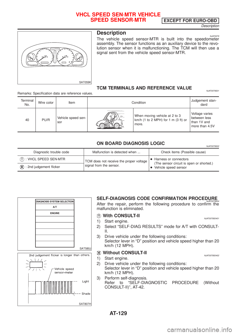
DescriptionNJAT0079The vehicle speed sensor´MTR is built into the speedometer
assembly. The sensor functions as an auxiliary device to the revo-
lution sensor when it is malfunctioning. The TCM will then use a
signal sent from the vehicle speed sensor´MTR.
TCM TERMINALS AND REFERENCE VALUENJAT0079S01Remarks: Specification data are reference values.
Terminal
No.Wire color Item ConditionJudgement stan-
dard
40 PU/RVehicle speed sen-
sor
When moving vehicle at 2 to 3
km/h (1 to 2 MPH) for1m(3ft)or
more.Voltage varies
between less
than 1V and
more than 4.5V
ON BOARD DIAGNOSIS LOGICNJAT0079S02
Diagnostic trouble code Malfunction is detected when ... Check items (Possible cause)
: VHCL SPEED SEN´MTR
TCM does not receive the proper voltage
signal from the sensor.+Harness or connectors
(The sensor circuit is open or shorted.)
+Vehicle speed sensor
: 2nd judgement flicker
SAT580J
SAT807H
SELF-DIAGNOSIS CODE CONFIRMATION PROCEDURENJAT0079S04After the repair, perform the following procedure to confirm the
malfunction is eliminated.
With CONSULT-IINJAT0079S04011) Start engine.
2) Select ªSELF-DIAG RESULTSº mode for A/T with CONSULT-
II.
3) Drive vehicle under the following conditions:
Selector lever in ªDº position and vehicle speed higher than 20
km/h (12 MPH).
Without CONSULT-IINJAT0079S04021) Start engine.
2) Drive vehicle under the following conditions:
Selector lever in ªDº position and vehicle speed higher than 20
km/h (12 MPH).
3) Perform self-diagnosis.
Refer to ªSELF-DIAGNOSTIC PROCEDURE (Without
CONSULT-II)º, AT-42.
VHCL SPEED SEN´MTR VEHICLE
SPEED SENSOR´MTR
EXCEPT FOR EURO-OBD
Description
AT-129
Page 1317 of 2493

Diagnostic ProcedureNJAT0080
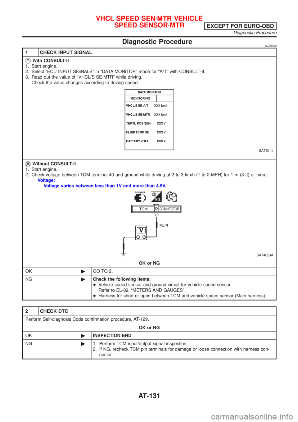
1 CHECK INPUT SIGNAL
With CONSULT-II
1. Start engine.
2. Select ªECU INPUT SIGNALSº in ªDATA MONITORº mode for ªA/Tº with CONSULT-II.
3. Read out the value of ªVHCL/S SE´MTRº while driving.
Check the value changes according to driving speed.
SAT614J
Without CONSULT-II
1. Start engine.
2. Check voltage between TCM terminal 40 and ground while driving at 2 to 3 km/h (1 to 2 MPH) for1m(3ft)ormore.
Voltage:
Voltage varies between less than 1V and more than 4.5V.
SAT465JA
OK or NG
OK©GO TO 2.
NG©Check the following items:
+Vehicle speed sensor and ground circuit for vehicle speed sensor
Refer to EL-89, ªMETERS AND GAUGESº.
+Harness for short or open between TCM and vehicle speed sensor (Main harness)
2 CHECK DTC
Perform Self-diagnosis Code confirmation procedure, AT-129.
OK or NG
OK©INSPECTION END
NG©1. Perform TCM input/output signal inspection.
2. If NG, recheck TCM pin terminals for damage or loose connection with harness con-
nector.
VHCL SPEED SEN´MTR VEHICLE
SPEED SENSOR´MTR
EXCEPT FOR EURO-OBD
Diagnostic Procedure
AT-131