2001 NISSAN ALMERA N16 check engine
[x] Cancel search: check enginePage 916 of 2493

AEC640
SEF111X
SEC163BA
MEC475B
Overall Function CheckNJEC0664Use this procedure to check the overall function of the cooling fan.
During this check, a DTC might not be confirmed.
WARNING:
Never remove the radiator cap when the engine is hot. Serious
burns could be caused by high pressure fluid escaping from
the radiator.
Wrap a thick cloth around the cap. Carefully remove the cap
by turning it a quarter turn to allow built-up pressure to
escape. Then turn the cap all the way off.
WITH CONSULT-IINJEC0664S011) Check the coolant level in the reservoir tank and radiator.
Allow engine to cool before checking coolant level.
If the coolant level in the reservoir tank and/or radiator is below
the proper range, skip the following steps and go to ªDiagnos-
tic Procedureº, EC-622.
2) Confirm whether customer filled the coolant or not. If customer
filled the coolant, skip the following steps and go to ªDiagnos-
tic Procedureº, EC-622.
3) Turn ignition switch ªONº.
4) Perform ªCOOLING FANº in ªACTIVE TESTº mode with CON-
SULT-II and make sure that cooling fans operate when touch-
ing ªHIGHº or ªLOWº.
If NG, go to ªDiagnostic Procedureº, EC-622.
WITHOUT CONSULT-IINJEC0664S021) Check the coolant level in the reservoir tank and radiator.
Allow engine to cool before checking coolant level.
If the coolant level in the reservoir tank and/or radiator is below
the proper range, skip the following steps and go to ªDiagnos-
tic Procedureº, EC-622.
2) Confirm whether customer filled the coolant or not. If customer
filled the coolant, skip the following steps and go to ªDiagnos-
tic Procedureº, EC-622.
3) Start engine.
Be careful not to overheat engine.
4) Set temperature control lever to full cold position.
5) Turn air conditioner switch ªONº.
6) Turn blower fan switch ªONº.
7) Run engine at idle for a few minutes with air conditioner oper-
ating.
Be careful not to overheat engine.
8) Make sure that cooling fans operate at low speed.
9) Turn ignition switch ªOFFº.
10) Turn air conditioner switch and blower fan switch ªOFFº.
11) Disconnect engine coolant temperature sensor harness con-
nector.
12) Connect 150Wresistor to engine coolant temperature sensor
harness connector.
13) Start engine and make sure that cooling fans operate at higher
speed than low speed.
Be careful not to overheat engine.
14) If NG, go to ªDiagnostic Procedureº, EC-622.
DTC P1217 OVER HEATYD
On Board Diagnosis Logic (Cont'd)
EC-620
Page 920 of 2493

4 CHECK COOLING FAN LOW SPEED OPERATION
Without CONSULT-II
1. Disconnect cooling fan relays-2 and -4.
SEF384Y
2. Start engine and let it idle.
3. Set temperature lever at full cold position.
4. Turn air conditioner switch ªONº.
5. Turn blower fan switch ªONº.
6. Make sure that cooling fans-1 and -2 operate at low speed.
SEC163BA
OK or NG
OK©GO TO 5.
NG©Check cooling fan low speed control circuit. (Go to PROCEDURE A, EC-627.)
DTC P1217 OVER HEATYD
Diagnostic Procedure (Cont'd)
EC-624
Page 921 of 2493

5 CHECK COOLING FAN HIGH SPEED OPERATION
Without CONSULT-II
1. Turn ignition switch ªOFFº.
2. Reconnect cooling fan relays-2 and -4.
3. Turn air conditioner switch and blower fan switch ªOFFº.
4. Disconnect engine coolant temperature sensor harness connector.
5. Connect 150Wresistor to engine coolant temperature sensor harness connector.
6. Restart engine and make sure that cooling fans-1 and -2 operate at high speed.
MEC475B
OK or NG
OK©GO TO 6.
NG©Check cooling fan high speed control circuit. (Go to PROCEDURE B, EC-630.)
6 CHECK COOLING SYSTEM FOR LEAK
Apply pressure to the cooling system with a tester, and check if the pressure drops.
Testing pressure: 157 kPa (1.57 bar, 1.6 kg/cm2, 23 psi)
CAUTION:
Higher than the specified pressure may cause radiator damage.
SLC754A
Pressure should not drop.
OK or NG
OK©GO TO 8.
NG©GO TO 7.
7 DETECT MALFUNCTIONING PART
Check the following for leak.
+Hose
+Radiator
+Water pump (Refer to LC-38, ªWater Pumpº.)
©Repair or replace.
DTC P1217 OVER HEATYD
Diagnostic Procedure (Cont'd)
EC-625
Page 923 of 2493
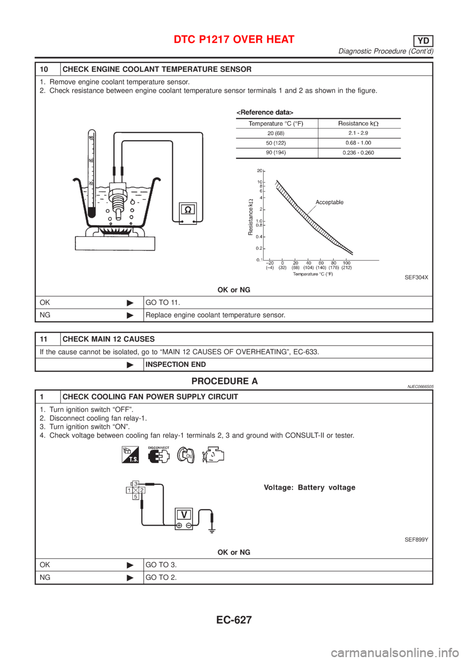
10 CHECK ENGINE COOLANT TEMPERATURE SENSOR
1. Remove engine coolant temperature sensor.
2. Check resistance between engine coolant temperature sensor terminals 1 and 2 as shown in the figure.
SEF304X
OK or NG
OK©GO TO 11.
NG©Replace engine coolant temperature sensor.
11 CHECK MAIN 12 CAUSES
If the cause cannot be isolated, go to ªMAIN 12 CAUSES OF OVERHEATINGº, EC-633.
©INSPECTION END
PROCEDURE ANJEC0666S05
1 CHECK COOLING FAN POWER SUPPLY CIRCUIT
1. Turn ignition switch ªOFFº.
2. Disconnect cooling fan relay-1.
3. Turn ignition switch ªONº.
4. Check voltage between cooling fan relay-1 terminals 2, 3 and ground with CONSULT-II or tester.
SEF899Y
OK or NG
OK©GO TO 3.
NG©GO TO 2.
DTC P1217 OVER HEATYD
Diagnostic Procedure (Cont'd)
EC-627
Page 929 of 2493
9 CHECK INTERMITTENT INCIDENT
1. Perform ªTROUBLE DIAGNOSIS FOR INTERMITTENT INCIDENTº, EC-559.
©INSPECTION END
Main 12 Causes of OverheatingNJEC0667
Engine Step Inspection item Equipment Condition Reference page
OFF 1+Blocked radiator
+Blocked radiator grille
+Blocked bumper+Visual No blocking Ð
2+Coolant mixture+Coolant tester 50 - 50% coolant mixture See MA-20, ªRECOM-
MENDED FLUIDS AND
LUBRICANTSº.
3+Coolant level+Visual Coolant up to MAX level
in reservoir tank and
radiator filler neckSee LC-17, ªChanging
Engine Coolantº.
4+Radiator cap+Pressure tester 78 - 98 kPa
(0.78 - 0.98 bar, 0.8 - 1.0
kg/cm
2, 11 - 14 psi)See LC-37, ªSystem
Checkº.
ON*
25+Coolant leaks+Visual No leaks See LC-37, ªSystem
Checkº.
ON*
26+Thermostat+Touch the upper and
lower radiator hosesBoth hoses should be
hotSee LC-40, ªThermostatº
and ªRadiatorº.
ON*
17+Cooling fan+CONSULT-II Operating See Trouble Diagnosis
for DTC P1217, EC-618.
OFF 8+Combustion gas leak+Color checker chemi-
cal tester 4 Gas ana-
lyzerNegative Ð
ON*
39+Coolant temperature
gauge+Visual Gauge less than 3/4
when drivingÐ
+Coolant overflow to
reservoir tank+Visual No overflow during driv-
ing and idlingSee LC-43, ªChanging
Engine Coolantº.
OFF*
410+Coolant return from
reservoir tank to radia-
tor+Visual Should be initial level in
reservoir tankSee LC-43, ªREFILLING
ENGINE COOLANTº.
OFF 11+Cylinder head+Straight gauge feeler
gauge0.1mm (0.004 in) Maxi-
mum distortion (warping)See EM-121, ªInspec-
tionº.
12+Cylinder block and
pistons+Visual No scuffing on cylinder
walls or pistonSee EM-143, ªInspec-
tionº.
*1: Turn the ignition switch ON.
*2: Engine running at 3,000 rpm for 10 minutes.
*3: Drive at 90 km/h (55 MPH) for 30 minutes and then let idle for 10 minutes.
*4: After 60 minutes of cool down time.
For more information, refer to LC-46, ªOVERHEATING CAUSE ANALYSISº.
DTC P1217 OVER HEATYD
Diagnostic Procedure (Cont'd)
EC-633
Page 931 of 2493
MONITOR ITEM CONDITION SPECIFICATION
BARO SEN+Ignition switch: ONAltitude
Approx.0m(0ft): Approx. 100.62
kPa (1.0062 bar, 1.026 kg/cm
2,
14.59 psi)
Approx. 1,000 m (3,281 ft): Approx.
88.95 kPa (0.8895 bar, 0.907
kg/cm
2, 12.90 psi)
Approx. 1,500 m (4,922 ft): Approx.
83.16 kPa (0.8316 bar, 0.848
kg/cm
2, 12.06 psi)
Approx. 2,000 m (6,562 ft): Approx.
78.36 kPa (0.7836 bar, 0.799
kg/cm
2, 11.36 psi)
ECM Terminals and Reference ValueNJEC0729Specification data are reference values and are measured between each terminal and ground.
CAUTION:
Do not use ECM ground terminals when measuring input/output voltage. Doing so may result in dam-
age to the ECM's transistor. Use a ground other than ECM terminals, such as the ground.
TERMI-
NAL
NO.WIRE
COLORITEM CONDITION DATA (DC Voltage)
313 L/WElectronic control fuel
injection pump[Engine is running]
+Warm-up condition
+Idle speedApproximately 0.1V
314 L/RElectronic control fuel
injection pump[Engine is running]
+Warm-up condition
+Idle speedApproximately 0.4V
316 PUElectronic control fuel
injection pump[Engine is running]
+Warm-up condition
+Idle speedApproximately 2.5V
317 PElectronic control fuel
injection pump[Engine is running]
+Warm-up condition
+Idle speedApproximately 2.5V
On Board Diagnosis LogicNJEC0730
DTC Malfunction is detected when .... Check Items (Possible cause)
P1241
0707+Fuel injection timing control system does not
function properly.+Harness or connectors
(Electronic control fuel injection pump circuit is
open or shorted.)
+Electronic control fuel injection pump
+Improper fuel quality
SEF817Y
DTC Confirmation ProcedureNJEC0731WITH CONSULT-IINJEC0731S011) Turn ignition switch ªONº and wait at least 2 seconds.
2) Select ªDATA MONITORº mode with CONSULT-II.
3) Start engine and run it for at least 2 seconds at idle speed.
(If engine does not run, turn ignition switch to ªSTARTº for at
least 2 seconds.)
4) Keep engine speed at more than 2,000 rpm for at least 10
seconds.
5) If DTC is detected, go to ªDiagnostic Procedureº, EC-638.
DTC P1241 P7´F/INJ TIMG FBYD
CONSULT-II Reference Value in Data Monitor Mode (Cont'd)
EC-635
Page 937 of 2493
MONITOR ITEM CONDITION SPECIFICATION
BARO SEN+Ignition switch: ONAltitude
Approx.0m(0ft): Approx. 100.62
kPa (1.0062 bar, 1.026 kg/cm
2,
14.59 psi)
Approx. 1,000 m (3,281 ft): Approx.
88.95 kPa (0.8895 bar, 0.907
kg/cm
2, 12.90 psi)
Approx. 1,500 m (4,922 ft): Approx.
83.16 kPa (0.8316 bar, 0.848
kg/cm
2, 12.06 psi)
Approx. 2,000 m (6,562 ft): Approx.
78.36 kPa (0.7836 bar, 0.799
kg/cm
2, 11.36 psi)
ECM Terminals and Reference ValueNJEC0716Specification data are reference values and are measured between each terminal and ground.
CAUTION:
Do not use ECM ground terminals when measuring input/output voltage. Doing so may result in dam-
age to the ECM's transistor. Use a ground other than ECM terminals, such as the ground.
TERMI-
NAL
NO.WIRE
COLORITEM CONDITION DATA (DC Voltage)
313 L/WElectronic control fuel
injection pump[Engine is running]
+Warm-up condition
+Idle speedApproximately 0.1V
314 L/RElectronic control fuel
injection pump[Engine is running]
+Warm-up condition
+Idle speedApproximately 0.4V
316 PUElectronic control fuel
injection pump[Engine is running]
+Warm-up condition
+Idle speedApproximately 2.5V
317 PElectronic control fuel
injection pump[Engine is running]
+Warm-up condition
+Idle speedApproximately 2.5V
On Board Diagnosis LogicNJEC0717
DTC Malfunction is detected when .... Check Items (Possible cause)
P1251
0704+Spill valve (Built-into electronic control fuel injec-
tion pump) does not function properly.+Harness or connectors
(Electronic control fuel injection pump circuit is
open or shorted.)
+Electronic control fuel injection pump
SEF817Y
DTC Confirmation ProcedureNJEC0718WITH CONSULT-IINJEC0718S011) Turn ignition switch ªONº and wait at least 2 seconds.
2) Select ªDATA MONITORº mode with CONSULT-II.
3) Start engine and run it for at least 2 seconds at idle speed.
(If engine does not run, turn ignition switch to ªSTARTº for at
least 2 seconds.)
4) If DTC is detected, go to ªDiagnostic Procedureº, EC-644.
WITHOUT CONSULT-IINJEC0718S021) Turn ignition switch ªONº and wait at least 2 seconds.
DTC P1251 P4´SPILL/V CIRCYD
CONSULT-II Reference Value in Data Monitor Mode (Cont'd)
EC-641
Page 943 of 2493
MONITOR ITEM CONDITION SPECIFICATION
BARO SEN+Ignition switch: ONAltitude
Approx.0m(0ft): Approx. 100.62
kPa (1.0062 bar, 1.026 kg/cm
2,
14.59 psi)
Approx. 1,000 m (3,281 ft): Approx.
88.95 kPa (0.8895 bar, 0.907
kg/cm
2, 12.90 psi)
Approx. 1,500 m (4,922 ft): Approx.
83.16 kPa (0.8316 bar, 0.848
kg/cm
2, 12.06 psi)
Approx. 2,000 m (6,562 ft): Approx.
78.36 kPa (0.7836 bar, 0.799
kg/cm
2, 11.36 psi)
ECM Terminals and Reference ValueNJEC0702Specification data are reference values and are measured between each terminal and ground.
CAUTION:
Do not use ECM ground terminals when measuring input/output voltage. Doing so may result in dam-
age to the ECM's transistor. Use a ground other than ECM terminals, such as the ground.
TERMI-
NAL
NO.WIRE
COLORITEM CONDITION DATA (DC Voltage)
313 L/WElectronic control fuel
injection pump[Engine is running]
+Warm-up condition
+Idle speedApproximately 0.1V
314 L/RElectronic control fuel
injection pump[Engine is running]
+Warm-up condition
+Idle speedApproximately 0.4V
316 PUElectronic control fuel
injection pump[Engine is running]
+Warm-up condition
+Idle speedApproximately 2.5V
317 PElectronic control fuel
injection pump[Engine is running]
+Warm-up condition
+Idle speedApproximately 2.5V
On Board Diagnosis LogicNJEC0703
DTC Malfunction is detected when .... Check Items (Possible cause)
P1337
0702+Injection pump control unit input signal [Crank-
shaft position sensor (TDC) signal] processing
function is malfunctioning.+Harness or connectors
(Electronic control fuel injection pump circuit is
open or shorted.)
+Electronic control fuel injection pump
SEF817Y
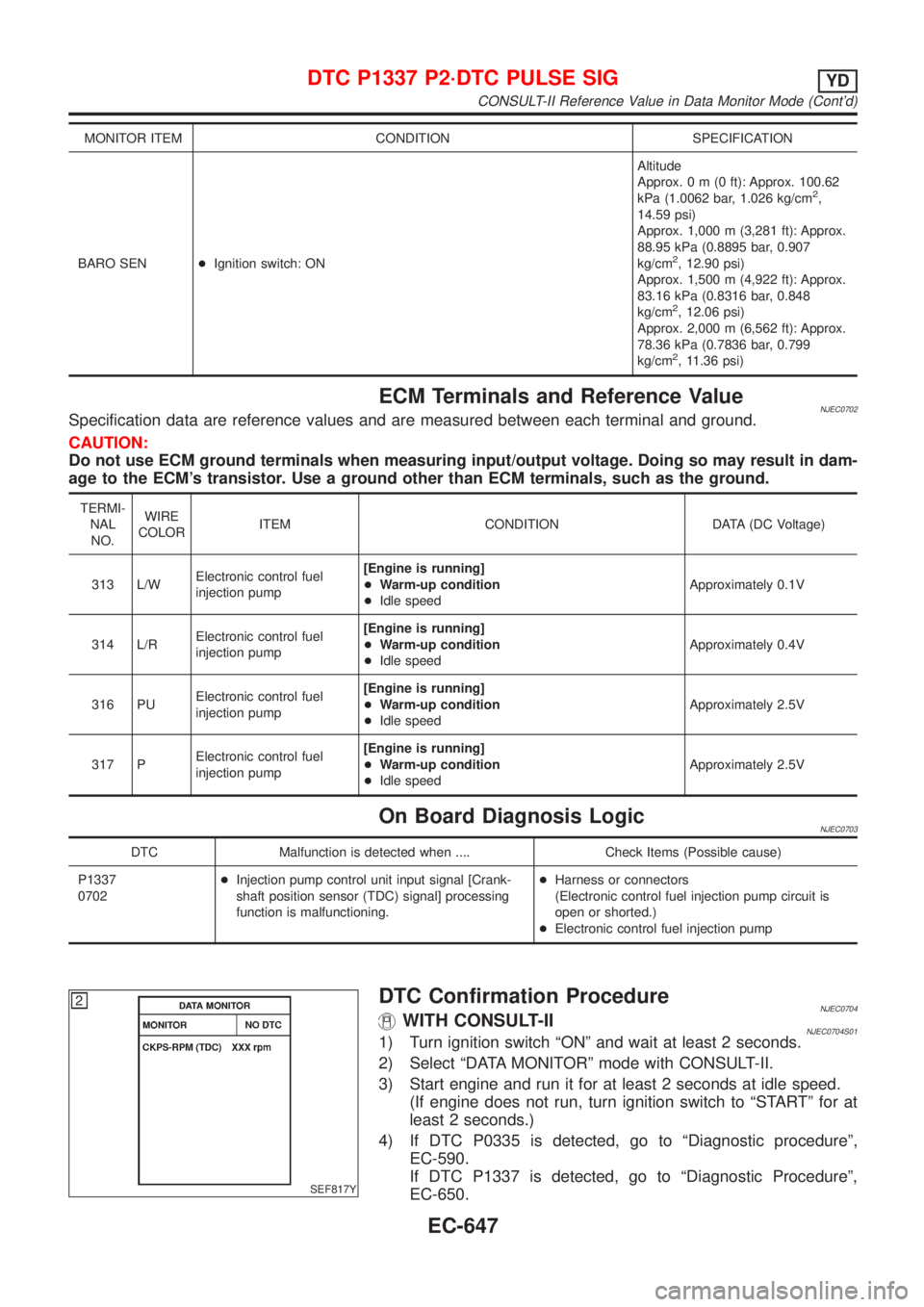
DTC Confirmation ProcedureNJEC0704WITH CONSULT-IINJEC0704S011) Turn ignition switch ªONº and wait at least 2 seconds.
2) Select ªDATA MONITORº mode with CONSULT-II.
3) Start engine and run it for at least 2 seconds at idle speed.
(If engine does not run, turn ignition switch to ªSTARTº for at
least 2 seconds.)
4) If DTC P0335 is detected, go to ªDiagnostic procedureº,
EC-590.
If DTC P1337 is detected, go to ªDiagnostic Procedureº,
EC-650.
DTC P1337 P2´DTC PULSE SIGYD
CONSULT-II Reference Value in Data Monitor Mode (Cont'd)
EC-647