2001 NISSAN ALMERA N16 torque
[x] Cancel search: torquePage 226 of 2493
SEM316A
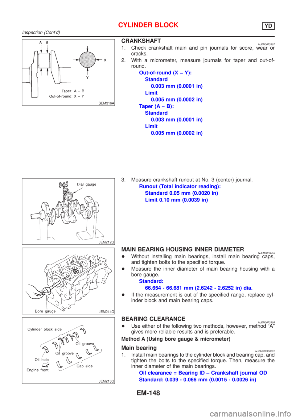
CRANKSHAFTNJEM0073S071. Check crankshaft main and pin journals for score, wear or
cracks.
2. With a micrometer, measure journals for taper and out-of-
round.
Out-of-round (X þ Y):
Standard
0.003 mm (0.0001 in)
Limit
0.005 mm (0.0002 in)
Taper (A þ B):
Standard
0.003 mm (0.0001 in)
Limit
0.005 mm (0.0002 in)
JEM212G
3. Measure crankshaft runout at No. 3 (center) journal.
Runout (Total indicator reading):
Standard 0.05 mm (0.0020 in)
Limit 0.10 mm (0.0039 in)
JEM214G
MAIN BEARING HOUSING INNER DIAMETERNJEM0073S15+Without installing main bearings, install main bearing caps,
and tighten bolts to the specified torque.
+Measure the inner diameter of main bearing housing with a
bore gauge.
Standard:
66.654 - 66.681 mm (2.6242 - 2.6252 in) dia.
+If the measurement is out of the specified range, replace cyl-
inder block and main bearing caps.
JEM213G
BEARING CLEARANCENJEM0073S08+Use either of the following two methods, however, method ªAº
gives more reliable results and is preferable.
Method A (Using bore gauge & micrometer)
Main bearingNJEM0073S08011. Install main bearings to the cylinder block and bearing cap, and
tighten the bolts to the specified torque. Then, measure the
inner diameter of the main bearings.
Oil clearance = Bearing ID ± Crankshaft journal OD
Standard: 0.039 - 0.066 mm (0.0015 - 0.0026 in)
CYLINDER BLOCKYD
Inspection (Cont'd)
EM-148
Page 228 of 2493
62.951 - 62.959
(2.4784 - 2.4787)2+Bearing grade No.
+Bearing thickness
+Oil clearance
+Identification colorSTD 2
1.824 - 1.828
(0.0718 - 0.0720)
0.039 - 0.066
(0.0015 - 0.0026)
GreenSTD 3
1.828 - 1.832
(0.0720 - 0.0721)
0.039 - 0.066
(0.0015 - 0.0026)
YellowSTD 4
1.832 - 1.836
(0.0721 - 0.0723)
0.039 - 0.066
(0.0015 - 0.0026)
Blue
3. When the specified oil clearance is not obtained with standard
size main bearings, use undersized bearings.
+When an undersized bearing is used, measure the inner diam-
eter of the bearing while the bearing is installed. Grind crank-
shaft journal so that the specified oil clearance is obtained.
JEM216G
Undersize bearing
Unit: mm (in)
Size Thickness
US 0.25 (0.0098) 1.949 - 1.953 (0.0767 - 0.0769)
CAUTION:
When grinding the crankshaft journal to use an undersize
bearing, avoid damaging the fillet R.
AEM027
Connecting Rod Bearing (Big end)NJEM0073S08021. Install connecting rod bearing to connecting rod and cap.
2. Install connecting rod cap to connecting rod.
Tighten bolts to the specified torque.
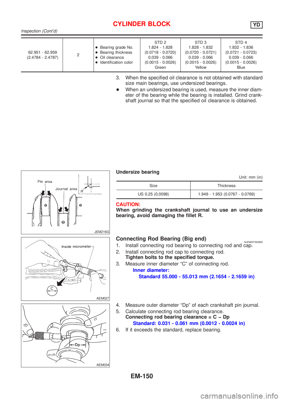
3. Measure inner diameter ªCº of connecting rod.
Inner diameter:
Standard 55.000 - 55.013 mm (2.1654 - 2.1659 in)
AEM034
4. Measure outer diameter ªDpº of each crankshaft pin journal.
5. Calculate connecting rod bearing clearance.
Connecting rod bearing clearance=CþDp
Standard: 0.031 - 0.061 mm (0.0012 - 0.0024 in)
6. If it exceeds the standard, replace bearing.
CYLINDER BLOCKYD
Inspection (Cont'd)
EM-150
Page 230 of 2493
Standard dimension R:
1.5 - 1.7 mm (0.0591 - 0.0669 in)
EM142
Method B (Using plastigage)
CAUTION:
+Do not turn crankshaft or connecting rod while plastigage
is being inserted.
+When bearing clearance exceeds the specified limit,
ensure that the proper bearing has been installed. If incor-
rect bearing clearance exists, use a thicker or undersized
main bearing to ensure specified clearance.
SEM502G
MAIN BEARING CRUSH HEIGHTNJEM0073S16+When the bearing cap is removed after being tightened to the
specified torque with main bearings installed, the tip end of
bearing must protrude.
Standard: There must be crush height.
+If the standard is not met, replace main bearings.
JEM219G
MAIN BEARING CAP BOLT DEFORMATIONNJEM0073S17+Measure the outer diameter of threaded area, d1 and d2, at the
points specified in the figure.
+When the necked point is identified at a point other than where
specified, measure at the point as d2.
+Calculate the difference between d1 and d2.
Limit: 0.13 mm (0.0051 in)
SEM673E
CONNECTING ROD BUSHING CLEARANCE (SMALL
END)
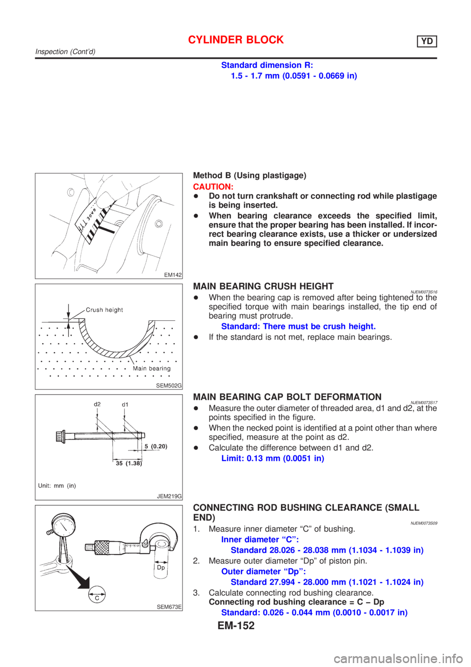
NJEM0073S091. Measure inner diameter ªCº of bushing.
Inner diameter ªCº:
Standard 28.026 - 28.038 mm (1.1034 - 1.1039 in)
2. Measure outer diameter ªDpº of piston pin.
Outer diameter ªDpº:
Standard 27.994 - 28.000 mm (1.1021 - 1.1024 in)
3. Calculate connecting rod bushing clearance.
Connecting rod bushing clearance=CþDp
Standard: 0.026 - 0.044 mm (0.0010 - 0.0017 in)
CYLINDER BLOCKYD
Inspection (Cont'd)
EM-152
Page 233 of 2493
JEM224G
4. Install main bearings and thrust bearings.
a. Remove debris, dust, and oil from the locations on the cylin-
der block and main bearing caps where bearings are installed.
b. Install thrust bearing on each side of cylinder block No. 3
housing.
+Install thrust bearings with oil groove facing in the direction of
the crankshaft arm (outside).
JEM213G
c. Be sure to install main bearings in the correct direction.
+Make sure those with oil holes or oil grooves are mounted on
the cylinder block side, and those without oil holes or oil
grooves are on the main cap side.
+Before installing, apply engine oil on the front (inner) surfaces
of bearings. Do not apply oil to the back surfaces, but thor-
oughly clean them.
+Align stopper notches on bearings and install.
+Check the oil holes on cylinder block and those on bearings
are aligned.
JEM225G
5. Install crankshaft to cylinder block.
+Make sure crankshaft rotates smoothly by hand.
6. Install main bearing caps.
+Identify main bearing caps by the punched mark. Install
correctly, matching the journal No. on the bearing cap and the
journal, with the front mark facing forward.
+Main bearing caps are commonly processed with the cylinder
block. Therefore, caps and cylinder block should be replaced
as a set.
JEM200G
JEM226G
7. Check the main bearing cap bolts for deformation.
Refer to EM-152, ªMAIN BEARING CAP BOLT DEFORMA-
TIONº.
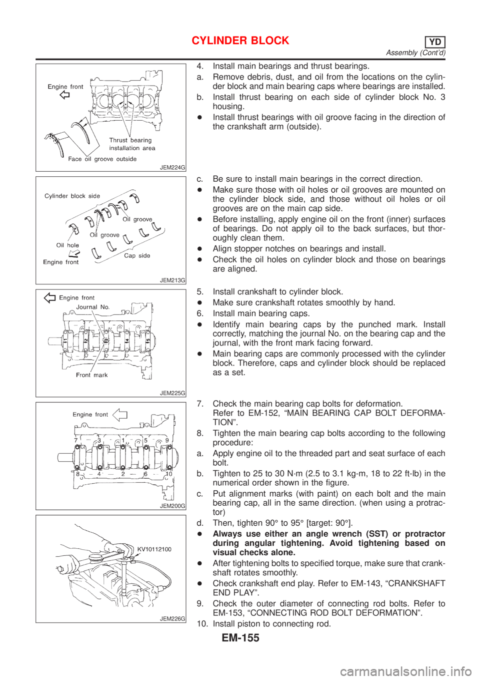
8. Tighten the main bearing cap bolts according to the following
procedure:
a. Apply engine oil to the threaded part and seat surface of each
bolt.
b. Tighten to 25 to 30 N´m (2.5 to 3.1 kg-m, 18 to 22 ft-lb) in the
numerical order shown in the figure.
c. Put alignment marks (with paint) on each bolt and the main
bearing cap, all in the same direction. (when using a protrac-
tor)
d. Then, tighten 90É to 95É [target: 90É].
+Always use either an angle wrench (SST) or protractor
during angular tightening. Avoid tightening based on
visual checks alone.
+After tightening bolts to specified torque, make sure that crank-
shaft rotates smoothly.
+Check crankshaft end play. Refer to EM-143, ªCRANKSHAFT
END PLAYº.
9. Check the outer diameter of connecting rod bolts. Refer to
EM-153, ªCONNECTING ROD BOLT DEFORMATIONº.
10. Install piston to connecting rod.
CYLINDER BLOCKYD
Assembly (Cont'd)
EM-155
Page 235 of 2493
JEM233G
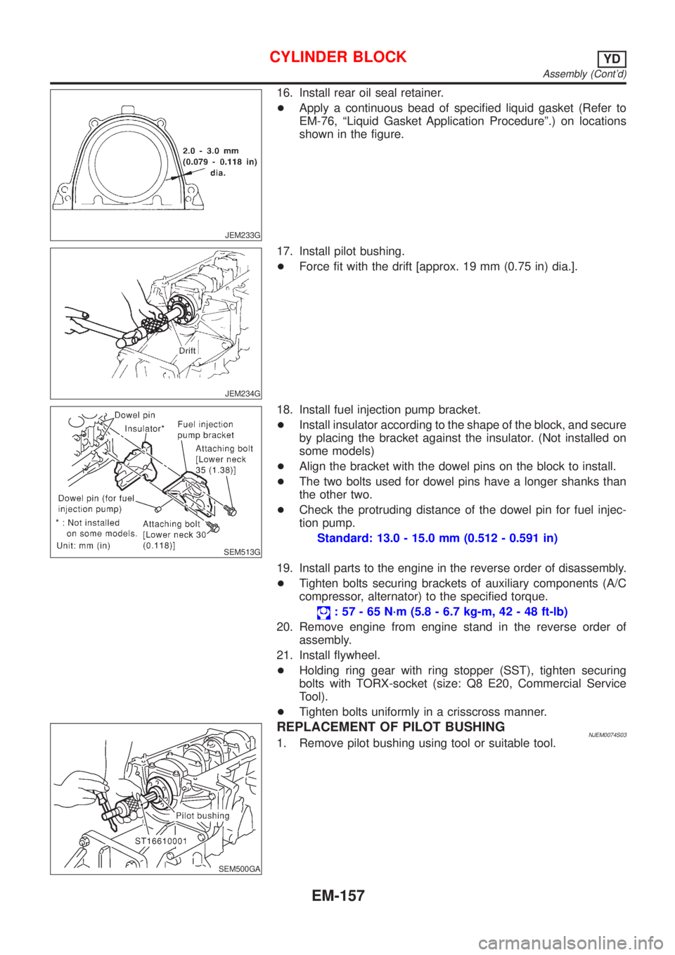
16. Install rear oil seal retainer.
+Apply a continuous bead of specified liquid gasket (Refer to
EM-76, ªLiquid Gasket Application Procedureº.) on locations
shown in the figure.
JEM234G
17. Install pilot bushing.
+Force fit with the drift [approx. 19 mm (0.75 in) dia.].
SEM513G
18. Install fuel injection pump bracket.
+Install insulator according to the shape of the block, and secure
by placing the bracket against the insulator. (Not installed on
some models)
+Align the bracket with the dowel pins on the block to install.
+The two bolts used for dowel pins have a longer shanks than
the other two.
+Check the protruding distance of the dowel pin for fuel injec-
tion pump.
Standard: 13.0 - 15.0 mm (0.512 - 0.591 in)
19. Install parts to the engine in the reverse order of disassembly.
+Tighten bolts securing brackets of auxiliary components (A/C
compressor, alternator) to the specified torque.
: 57 - 65 N´m (5.8 - 6.7 kg-m, 42 - 48 ft-lb)
20. Remove engine from engine stand in the reverse order of
assembly.
21. Install flywheel.
+Holding ring gear with ring stopper (SST), tighten securing
bolts with TORX-socket (size: Q8 E20, Commercial Service
Tool).
+Tighten bolts uniformly in a crisscross manner.
SEM500GA
REPLACEMENT OF PILOT BUSHINGNJEM0074S031. Remove pilot bushing using tool or suitable tool.
CYLINDER BLOCKYD
Assembly (Cont'd)
EM-157
Page 315 of 2493

SEF605X
+Do not operate fuel pump when there is no fuel in lines.
+Tighten fuel hose clamps to the specified torque.
SEF709Y
+Do not depress accelerator pedal when starting.
+Immediately after starting, do not rev up engine unneces-
sarily.
+Do not rev up engine just prior to shutdown.
SEF708Y
+When installing C.B. ham radio or a mobile phone, be sure
to observe the following as it may adversely affect elec-
tronic control systems depending on installation location.
1)Keep the antenna as far as possible from the electronic
control units.
2)Keep the antenna feeder line more than 20 cm (8 in) away
from the harness of electronic controls.
Do not let them run parallel for a long distance.
3)Adjust the antenna and feeder line so that the standing-
wave ratio can be kept smaller.
4)Be sure to ground the radio to vehicle body.
Wiring Diagrams and Trouble DiagnosisNJEC0006When you read Wiring diagrams, refer to the following:
+GI-12, ªHOW TO READ WIRING DIAGRAMSº
+EL-10, ªPOWER SUPPLY ROUTINGº for power distribution
circuit
When you perform trouble diagnosis, refer to the following:
+GI-31, ªHOW TO FOLLOW TEST GROUP IN TROUBLE
DIAGNOSISº
+GI-21, ªHOW TO PERFORM EFFICIENT DIAGNOSIS FOR
AN ELECTRICAL INCIDENTº
PRECAUTIONSQG
Engine Fuel & Emission Control System (Cont'd)
EC-19
Page 334 of 2493
SEF094Y
SEF214Y
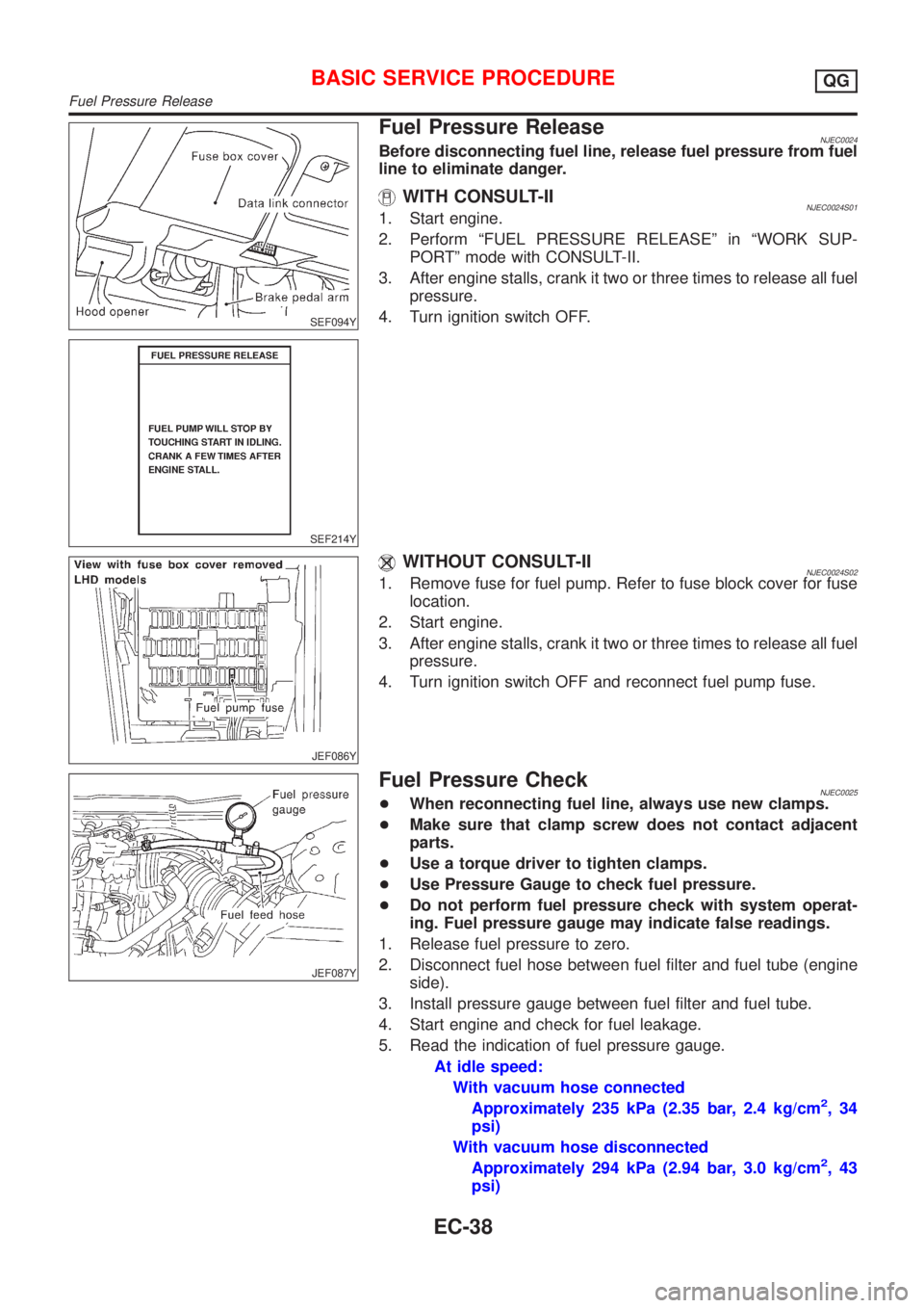
Fuel Pressure ReleaseNJEC0024Before disconnecting fuel line, release fuel pressure from fuel
line to eliminate danger.
WITH CONSULT-IINJEC0024S011. Start engine.
2. Perform ªFUEL PRESSURE RELEASEº in ªWORK SUP-
PORTº mode with CONSULT-II.
3. After engine stalls, crank it two or three times to release all fuel
pressure.
4. Turn ignition switch OFF.
JEF086Y
WITHOUT CONSULT-IINJEC0024S021. Remove fuse for fuel pump. Refer to fuse block cover for fuse
location.
2. Start engine.
3. After engine stalls, crank it two or three times to release all fuel
pressure.
4. Turn ignition switch OFF and reconnect fuel pump fuse.
JEF087Y
Fuel Pressure CheckNJEC0025+When reconnecting fuel line, always use new clamps.
+Make sure that clamp screw does not contact adjacent
parts.
+Use a torque driver to tighten clamps.
+Use Pressure Gauge to check fuel pressure.
+Do not perform fuel pressure check with system operat-
ing. Fuel pressure gauge may indicate false readings.
1. Release fuel pressure to zero.
2. Disconnect fuel hose between fuel filter and fuel tube (engine
side).
3. Install pressure gauge between fuel filter and fuel tube.
4. Start engine and check for fuel leakage.
5. Read the indication of fuel pressure gauge.
At idle speed:
With vacuum hose connected
Approximately 235 kPa (2.35 bar, 2.4 kg/cm
2,34
psi)
With vacuum hose disconnected
Approximately 294 kPa (2.94 bar, 3.0 kg/cm
2,43
psi)
BASIC SERVICE PROCEDUREQG
Fuel Pressure Release
EC-38
Page 336 of 2493

JEF089Y
7. Align protrusions of fuel tubes with those of fuel injectors.
Insert fuel injectors straight into fuel tubes.
8. After properly inserting fuel injectors, check to make sure that
fuel tube protrusions are engaged with those of fuel injectors,
and that flanges of fuel tubes are engaged with clips.
JEF815Y
9. Tighten fuel tube assembly mounting nuts in numerical
sequence (indicated in the Figure at left) and in two stages.
: Tightening torque N´m (kg-m, ft-lb)
1st stage:
12 - 13 (1.2 - 1.4, 9 - 10)
2nd stage:
17 - 23 (1.7 - 2.4, 13 - 17)
10. Insert fuel hoses into fuel tubes so that ends of fuel hoses butt
up against fuel tubes; fasten with clamps, avoiding bulges.
CAUTION:
After properly connecting fuel tube assembly to injector and
fuel hose, check connection for fuel leakage.
BASIC SERVICE PROCEDUREQG
Injector (Cont'd)
EC-40