Page 481 of 2493
7) Make sure that ªOKº is displayed after touching ªSELF-DIAG
RESULTSº. If ªNGº is displayed, refer to ªDiagnostic
Procedureº, EC-185.
SEF011X
Overall Function CheckNJEC0108Use this procedure to check the overall function of the heated oxy-
gen sensor 1 (front) circuit. During this check, a 1st trip DTC might
not be confirmed.
Without CONSULT-II
1) Start engine and warm it up to normal operating temperature.
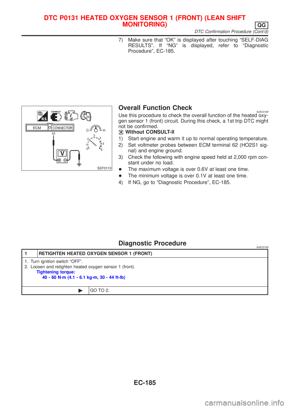
2) Set voltmeter probes between ECM terminal 62 (HO2S1 sig-
nal) and engine ground.
3) Check the following with engine speed held at 2,000 rpm con-
stant under no load.
+The maximum voltage is over 0.6V at least one time.
+The minimum voltage is over 0.1V at least one time.
4) If NG, go to ªDiagnostic Procedureº, EC-185.
Diagnostic ProcedureNJEC0109
1 RETIGHTEN HEATED OXYGEN SENSOR 1 (FRONT)
1. Turn ignition switch ªOFFº.
2. Loosen and retighten heated oxygen sensor 1 (front).
Tightening torque:
40 - 60 N´m (4.1 - 6.1 kg-m, 30 - 44 ft-lb)
©GO TO 2.
DTC P0131 HEATED OXYGEN SENSOR 1 (FRONT) (LEAN SHIFT
MONITORING)
QG
DTC Confirmation Procedure (Cont'd)
EC-185
Page 487 of 2493
7) Make sure that ªOKº is displayed after touching ªSELF-DIAG
RESULTSº. If ªNGº is displayed, refer to ªDiagnostic
Procedureº, EC-191.
SEF011X
Overall Function CheckNJEC0116Use this procedure to check the overall function of the heated oxy-
gen sensor 1 (front) circuit. During this check, a 1st trip DTC might
not be confirmed.
Without CONSULT-II
1) Start engine and warm it up to normal operating temperature.
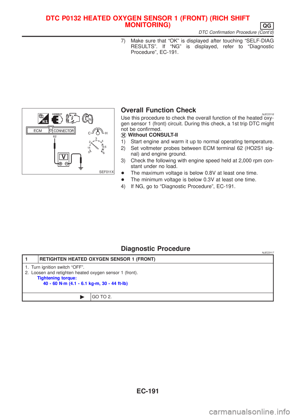
2) Set voltmeter probes between ECM terminal 62 (HO2S1 sig-
nal) and engine ground.
3) Check the following with engine speed held at 2,000 rpm con-
stant under no load.
+The maximum voltage is below 0.8V at least one time.
+The minimum voltage is below 0.3V at least one time.
4) If NG, go to ªDiagnostic Procedureº, EC-191.
Diagnostic ProcedureNJEC0117
1 RETIGHTEN HEATED OXYGEN SENSOR 1 (FRONT)
1. Turn ignition switch ªOFFº.
2. Loosen and retighten heated oxygen sensor 1 (front).
Tightening torque:
40 - 60 N´m (4.1 - 6.1 kg-m, 30 - 44 ft-lb)
©GO TO 2.
DTC P0132 HEATED OXYGEN SENSOR 1 (FRONT) (RICH SHIFT
MONITORING)
QG
DTC Confirmation Procedure (Cont'd)
EC-191
Page 495 of 2493
Diagnostic ProcedureNJEC0126
1 RETIGHTEN GROUND SCREWS
1. Turn ignition switch ªOFFº.
2. Loosen and retighten engine ground screws.
JEF104Y
©GO TO 2.
2 RETIGHTEN HEATED OXYGEN SENSOR 1 (FRONT)
Loosen and retighten heated oxygen sensor 1 (front).
Tightening torque:
40 - 60 N´m (4.1 - 6.1 kg-m, 30 - 44 ft-lb)
©GO TO 3.
3 CHECK EXHAUST AIR LEAK
1. Start engine and run it at idle.
2. Listen for an exhaust air leak before three way catalyst.
SEF099P
OK or NG
OK©GO TO 4.
NG©Repair or replace.
4 CHECK FOR INTAKE AIR LEAK
Listen for an intake air leak after the mass air flow sensor.
OK or NG
OK©GO TO 5.
NG©Repair or replace.
DTC P0133 HEATED OXYGEN SENSOR 1 (FRONT)
(RESPONSE MONITORING)
QG
Diagnostic Procedure
EC-199
Page 502 of 2493

Diagnostic ProcedureNJEC0134
1 RETIGHTEN HEATED OXYGEN SENSOR 1 (FRONT)
Loosen and retighten heated oxygen sensor 1 (front).
Tightening torque:
40 - 60 N´m (4.1 - 6.1 kg-m, 30 - 44 ft-lb)
©GO TO 2.
2 CHECK INPUT SIGNAL CIRCUIT
1. Disconnect heated oxygen sensor 1 (front) harness connector and ECM harness connector.
SEF012XA
2. Check harness continuity between ECM terminal 62 and heated oxygen sensor 1 (front) harness connector terminal 2.
Refer to wiring diagram.
Continuity should exist.
3. Check harness continuity between ECM terminal 62 (or terminal 2) and ground.
Continuity should not exist.
4. Also check harness for short to power.
OK or NG
OK©GO TO 3.
NG©Repair open circuit or short to ground or short to power in harness or connectors.
3 CHECK HARNESS CONNECTOR
Check heated oxygen sensor 1 (front) harness connector for water.
Water should not exist.
OK or NG
OK©GO TO 4.
NG©Repair or replace harness connector.
4 CHECK HEATED OXYGEN SENSOR 1 (FRONT)
Refer to ªComponent Inspectionº, EC-207.
OK or NG
OK©GO TO 5.
NG©Replace heated oxygen sensor 1 (front).
5 CHECK INTERMITTENT INCIDENT
Perform ªTROUBLE DIAGNOSIS FOR INTERMITTENT INCIDENTº, EC-144.
©INSPECTION END
DTC P0134 HEATED OXYGEN SENSOR 1 (FRONT) (HIGH VOLTAGE)QG
Diagnostic Procedure
EC-206
Page 672 of 2493
4 RETIGHTEN GROUND SCREWS
1. Turn ignition switch ªOFFº.
2. Loosen and retighten engine ground screws.
JEF104Y
3. Disconnect heated oxygen sensor 1 (front) harness connector.
SEF012XA
©GO TO 5.
5 RETIGHTEN HEATED OXYGEN SENSOR 1 (FRONT)
Loosen and retighten corresponding heated oxygen sensor 1 (front).
Tightening torque:
40 - 50 N´m (4.1 - 5.1 kg-m, 30 - 37 ft-lb)
©GO TO 6.
6 CHECK INPUT SIGNAL CIRCUIT
1. Disconnect ECM harness connector.
2. Check harness continuity between ECM terminal 62 and heated oxygen sensor 1 (front) harness connector terminal 2.
Refer to wiring diagram.
Continuity should exist.
3. Check harness continuity between ECM terminal 62 (or terminal 2) and ground.
Continuity should not exist.
4. Also check harness for short to power.
OK or NG
OK©GO TO 7.
NG©Repair open circuit or short to ground or short to power in harness or connectors.
HEATED OXYGEN SENSOR 1 (FRONT)QG
Diagnostic Procedure (Cont'd)
EC-376
Page 980 of 2493
15 CHECK HARNESS CONTINUITY BETWEEN GLOW RELAY AND GLOW PLUG FOR OPEN AND SHORT
1. Disconnect glow plug harness connector.
2. Check harness continuity between glow relay terminal 3 and glow plug harness connector. Refer to Wiring Diagram.
Continuity should exist.
3. Also check harness for short to ground and short to power.
OK or NG
OK©GO TO 16.
NG©Repair open circuit or short to ground or short to power in harness or connectors.
16 CHECK GLOW RELAY
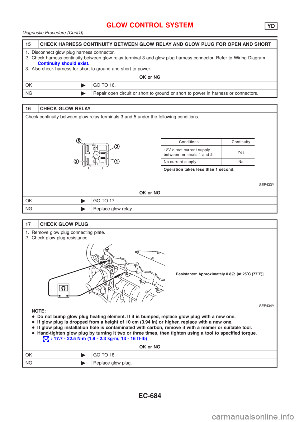
Check continuity between glow relay terminals 3 and 5 under the following conditions.
SEF433Y
OK or NG
OK©GO TO 17.
NG©Replace glow relay.
17 CHECK GLOW PLUG
1. Remove glow plug connecting plate.
2. Check glow plug resistance.
SEF434Y
NOTE:
+Do not bump glow plug heating element. If it is bumped, replace glow plug with a new one.
+If glow plug is dropped from a height of 10 cm (3.94 in) or higher, replace with a new one.
+If glow plug installation hole is contaminated with carbon, remove it with a reamer or suitable tool.
+Hand-tighten glow plug by turning it two or three times, then tighten using a tool to specified torque.
: 17.7 - 22.5 N´m (1.8 - 2.3 kg-m, 13 - 16 ft-lb)
OK or NG
OK©GO TO 18.
NG©Replace glow plug.
GLOW CONTROL SYSTEMYD
Diagnostic Procedure (Cont'd)
EC-684
Page 1003 of 2493
SMA803A
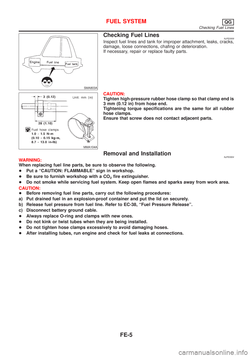
Checking Fuel LinesNJFE0009Inspect fuel lines and tank for improper attachment, leaks, cracks,
damage, loose connections, chafing or deterioration.
If necessary, repair or replace faulty parts.
MMA104A
CAUTION:
Tighten high-pressure rubber hose clamp so that clamp end is
3 mm (0.12 in) from hose end.
Tightening torque specifications are the same for all rubber
hose clamps.
Ensure that screw does not contact adjacent parts.
Removal and InstallationNJFE0004WARNING:
When replacing fuel line parts, be sure to observe the following.
+Put a ªCAUTION: FLAMMABLEº sign in workshop.
+Be sure to furnish workshop with a CO
2fire extinguisher.
+Do not smoke while servicing fuel system. Keep open flames and sparks away from work area.
CAUTION:
+Before removing fuel line parts, carry out the following procedures:
a) Put drained fuel in an explosion-proof container and put the lid on securely.
b) Release fuel pressure from fuel line. Refer to EC-38, ªFuel Pressure Releaseº.
c) Disconnect battery ground cable.
+Always replace O-ring and clamps with new ones.
+Do not kink or twist tubes when they are being installed.
+Do not tighten hose clamps excessively to avoid damaging hoses.
+After installing tubes, run engine and check for fuel leaks at connections.
FUEL SYSTEMQG
Checking Fuel Lines
FE-5
Page 1009 of 2493
SMA211A
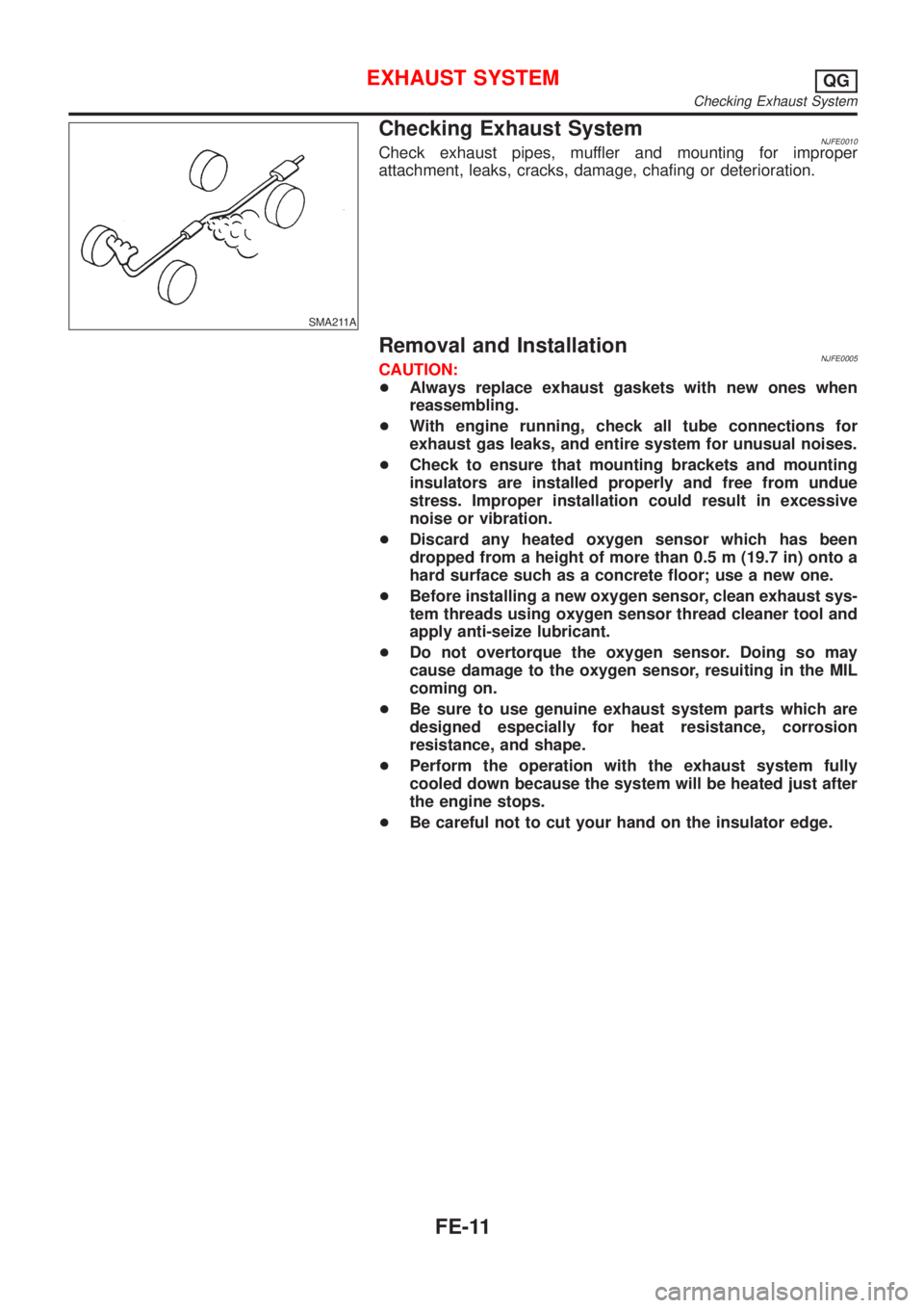
Checking Exhaust SystemNJFE0010Check exhaust pipes, muffler and mounting for improper
attachment, leaks, cracks, damage, chafing or deterioration.
Removal and InstallationNJFE0005CAUTION:
+Always replace exhaust gaskets with new ones when
reassembling.
+With engine running, check all tube connections for
exhaust gas leaks, and entire system for unusual noises.
+Check to ensure that mounting brackets and mounting
insulators are installed properly and free from undue
stress. Improper installation could result in excessive
noise or vibration.
+Discard any heated oxygen sensor which has been
dropped from a height of more than 0.5 m (19.7 in) onto a
hard surface such as a concrete floor; use a new one.
+Before installing a new oxygen sensor, clean exhaust sys-
tem threads using oxygen sensor thread cleaner tool and
apply anti-seize lubricant.
+Do not overtorque the oxygen sensor. Doing so may
cause damage to the oxygen sensor, resuiting in the MIL
coming on.
+Be sure to use genuine exhaust system parts which are
designed especially for heat resistance, corrosion
resistance, and shape.
+Perform the operation with the exhaust system fully
cooled down because the system will be heated just after
the engine stops.
+Be careful not to cut your hand on the insulator edge.
EXHAUST SYSTEMQG
Checking Exhaust System
FE-11