2001 NISSAN ALMERA N16 torque
[x] Cancel search: torquePage 1014 of 2493
SMA803A
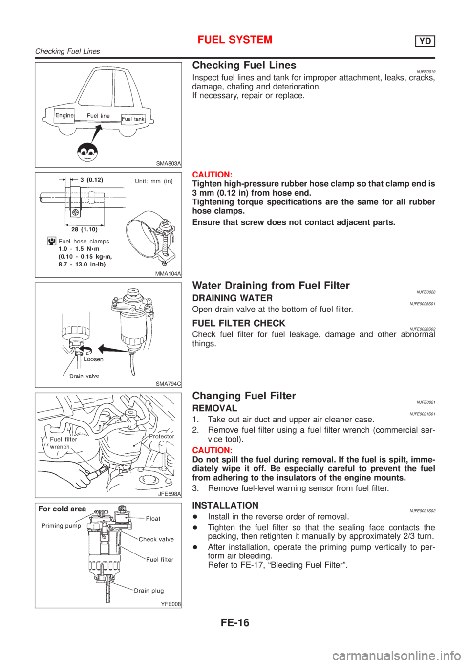
Checking Fuel LinesNJFE0019Inspect fuel lines and tank for improper attachment, leaks, cracks,
damage, chafing and deterioration.
If necessary, repair or replace.
MMA104A
CAUTION:
Tighten high-pressure rubber hose clamp so that clamp end is
3 mm (0.12 in) from hose end.
Tightening torque specifications are the same for all rubber
hose clamps.
Ensure that screw does not contact adjacent parts.
SMA794C
Water Draining from Fuel FilterNJFE0028DRAINING WATERNJFE0028S01Open drain valve at the bottom of fuel filter.
FUEL FILTER CHECKNJFE0028S02Check fuel filter for fuel leakage, damage and other abnormal
things.
JFE598A
Changing Fuel FilterNJFE0021REMOVALNJFE0021S011. Take out air duct and upper air cleaner case.
2. Remove fuel filter using a fuel filter wrench (commercial ser-
vice tool).
CAUTION:
Do not spill the fuel during removal. If the fuel is spilt, imme-
diately wipe it off. Be especially careful to prevent the fuel
from adhering to the insulators of the engine mounts.
3. Remove fuel-level warning sensor from fuel filter.
YFE008
INSTALLATIONNJFE0021S02+Install in the reverse order of removal.
+Tighten the fuel filter so that the sealing face contacts the
packing, then retighten it manually by approximately 2/3 turn.
+After installation, operate the priming pump vertically to per-
form air bleeding.
Refer to FE-17, ªBleeding Fuel Filterº.
FUEL SYSTEMYD
Checking Fuel Lines
FE-16
Page 1029 of 2493
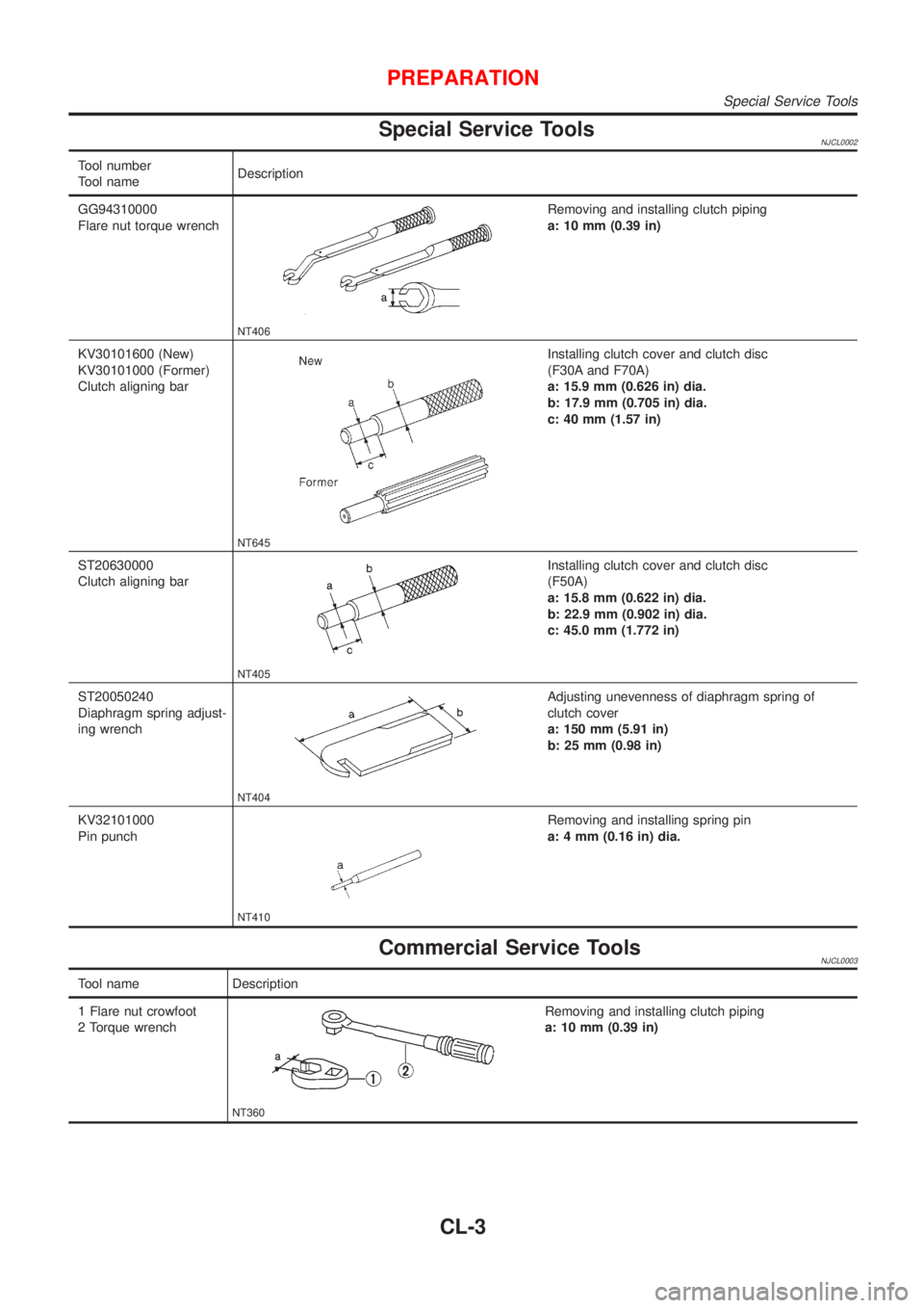
Special Service ToolsNJCL0002
Tool number
Tool nameDescription
GG94310000
Flare nut torque wrench
NT406
Removing and installing clutch piping
a: 10 mm (0.39 in)
KV30101600 (New)
KV30101000 (Former)
Clutch aligning bar
NT645
Installing clutch cover and clutch disc
(F30A and F70A)
a: 15.9 mm (0.626 in) dia.
b: 17.9 mm (0.705 in) dia.
c: 40 mm (1.57 in)
ST20630000
Clutch aligning bar
NT405
Installing clutch cover and clutch disc
(F50A)
a: 15.8 mm (0.622 in) dia.
b: 22.9 mm (0.902 in) dia.
c: 45.0 mm (1.772 in)
ST20050240
Diaphragm spring adjust-
ing wrench
NT404
Adjusting unevenness of diaphragm spring of
clutch cover
a: 150 mm (5.91 in)
b: 25 mm (0.98 in)
KV32101000
Pin punch
NT410
Removing and installing spring pin
a: 4 mm (0.16 in) dia.
Commercial Service ToolsNJCL0003
Tool name Description
1 Flare nut crowfoot
2 Torque wrench
NT360
Removing and installing clutch piping
a: 10 mm (0.39 in)
PREPARATION
Special Service Tools
CL-3
Page 1036 of 2493
CLUTCH PEDAL ADJUSTMENTNJCL0006S04Pedal StrokeNJCL0006S04011. Loosen the pedal stopper bolt completely (so there is no con-
tact between pedal and stopper bolt).
2. Adjust pedal stroke to the specified value with the master cyl-
inder push rod.
3. Adjust the pedal stopper bolt until it is just in contact with the
pedal, then tighten the lock nut.
4. Once stroke is set to specification, adjust clutch pedal free
play.
Pedal stroke ªSº.
Refer to ªSDSº, CL-24.
Pedal Free PlayNJCL0006S04021. Adjust pedal free play to the specified value with the master
cylinder push rod.
2. Tighten lock nut of the master cylinder push rod.
+Push on the clutch pedal until resistance is felt, and check the
distance the pedal moves.
Pedal free play ªAº.
Refer to ªSDSº, CL-24.
SCL838
SCL839
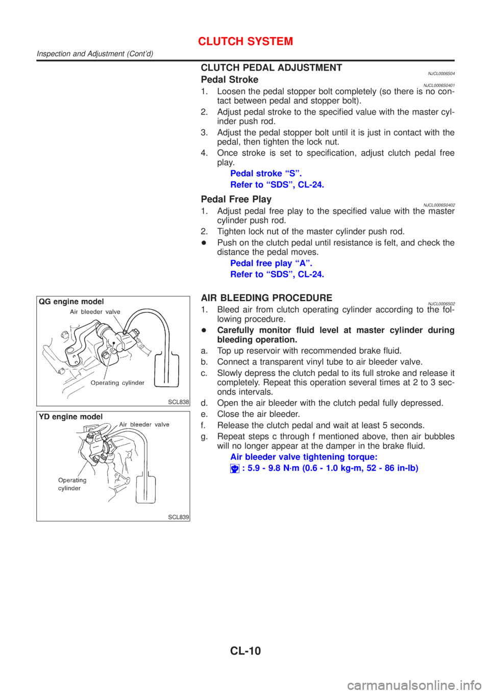
AIR BLEEDING PROCEDURENJCL0006S021. Bleed air from clutch operating cylinder according to the fol-
lowing procedure.
+Carefully monitor fluid level at master cylinder during
bleeding operation.
a. Top up reservoir with recommended brake fluid.
b. Connect a transparent vinyl tube to air bleeder valve.
c. Slowly depress the clutch pedal to its full stroke and release it
completely. Repeat this operation several times at 2 to 3 sec-
onds intervals.
d. Open the air bleeder with the clutch pedal fully depressed.
e. Close the air bleeder.
f. Release the clutch pedal and wait at least 5 seconds.
g. Repeat steps c through f mentioned above, then air bubbles
will no longer appear at the damper in the brake fluid.
Air bleeder valve tightening torque:
: 5.9 - 9.8 N´m (0.6 - 1.0 kg-m, 52 - 86 in-lb)
CLUTCH SYSTEM
Inspection and Adjustment (Cont'd)
CL-10
Page 1038 of 2493
RemovalNJCL00081. Drain brake fluid.
CAUTION:
Be careful not to splash brake fluid on painted areas; it may
cause paint damage. If brake fluid is splashed on painted
areas, wash it away with water immediately.
2. Remove clutch tube using a flare nut wrench.
3. Remove snap pin between clutch pedal and push rod, and
remove clevis pin.
4. Unscrew master cylinder assembly mounting nuts and remove
master cylinder assembly from vehicle.
InstallationNJCL00091. Connect clutch tube to master cylinder assembly, and hand-
tighten flare nut.
2. Install master cylinder assembly to vehicle, and tighten mount-
ing nuts to the specified torque.
: 11 - 14 N´m (1.1 - 1.5 kg-m,8-10ft-lb)
3. Tighten clutch tube flare nut using a flare nut torque wrench.
: 15 - 18 N´m (1.5 - 1.8 kg-m, 11 - 13 ft-lb)
4. After installing clevis pin, install snap pin to connect clutch
pedal to push rod.
5. After finishing the operation, bleed air from clutch piping con-
nector and operating cylinder. (Refer to ªAir Bleeding
Procedureº, CL-10.)
SCL725
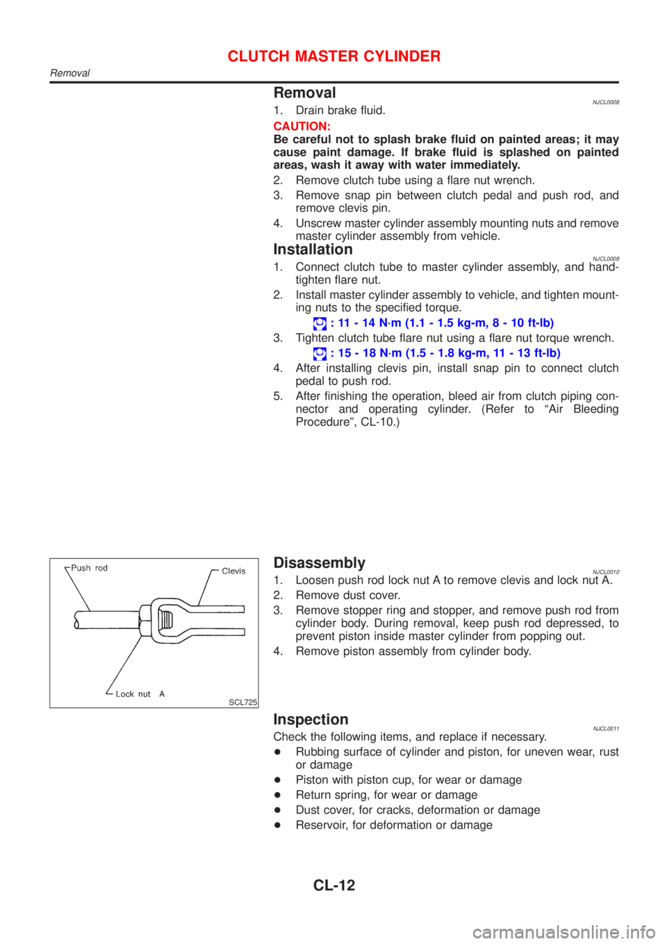
DisassemblyNJCL00101. Loosen push rod lock nut A to remove clevis and lock nut A.
2. Remove dust cover.
3. Remove stopper ring and stopper, and remove push rod from
cylinder body. During removal, keep push rod depressed, to
prevent piston inside master cylinder from popping out.
4. Remove piston assembly from cylinder body.
InspectionNJCL0011Check the following items, and replace if necessary.
+Rubbing surface of cylinder and piston, for uneven wear, rust
or damage
+Piston with piston cup, for wear or damage
+Return spring, for wear or damage
+Dust cover, for cracks, deformation or damage
+Reservoir, for deformation or damage
CLUTCH MASTER CYLINDER
Removal
CL-12
Page 1039 of 2493
AssemblyNJCL00121. Apply rubber lubricant to the sliding part of piston assembly,
and insert piston assembly.
2. After installing stopper to push rod, install stopper ring while
keeping piston assembly depressed by hand, so that piston
assembly will not pop out.
CAUTION:
Stopper ring cannot be reused. Always use a new stopper ring
for assembly.
3. Install dust cover.
4. Install clevis to push rod, and tighten lock nut A to the speci-
fied torque.
:8-10N´m(0.8 - 1.1 kg-m, 70 - 95 in-lb)
5. Install spring pin using a pin punch.
CLUTCH MASTER CYLINDER
Assembly
CL-13
Page 1042 of 2493
SCL729
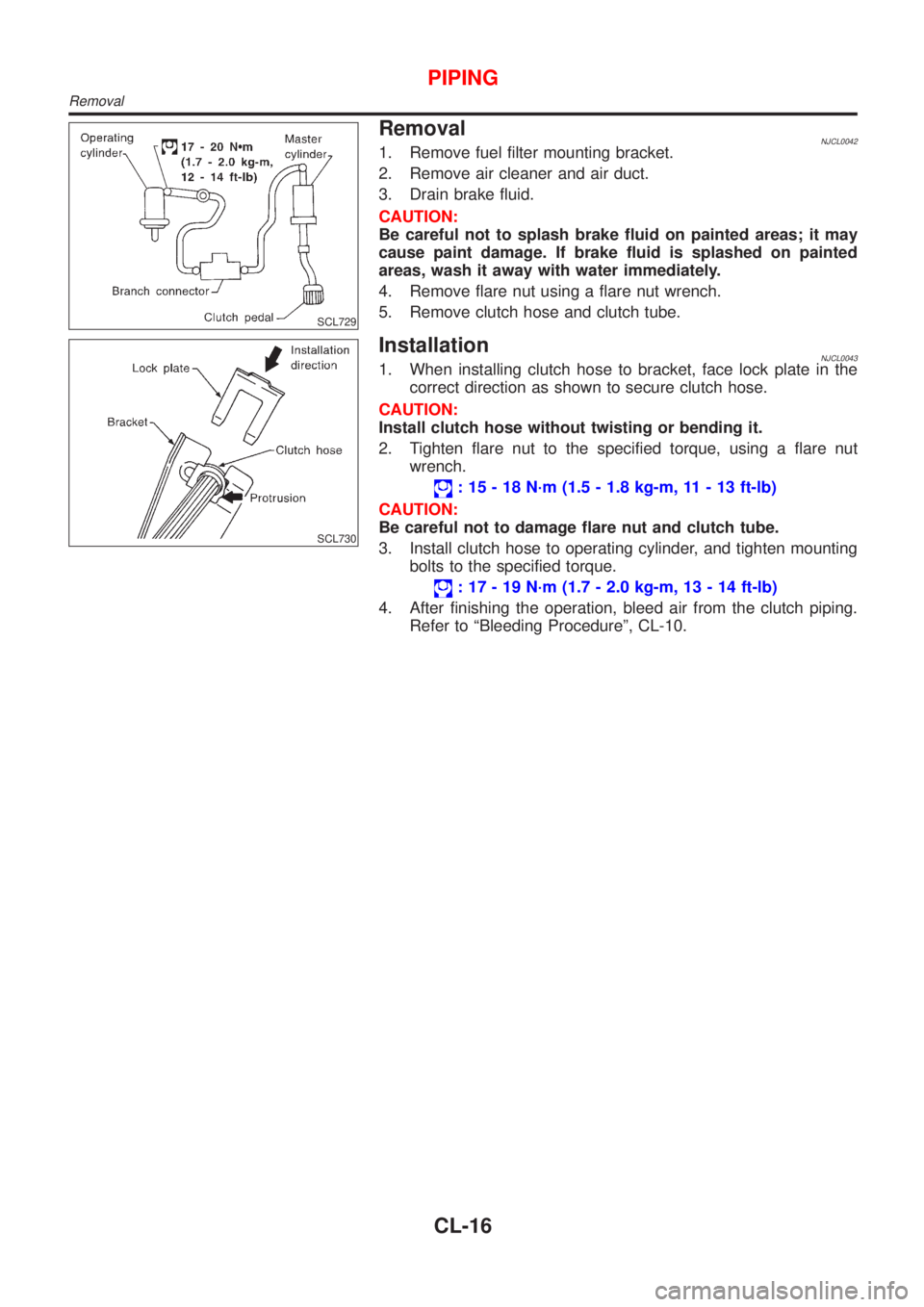
RemovalNJCL00421. Remove fuel filter mounting bracket.
2. Remove air cleaner and air duct.
3. Drain brake fluid.
CAUTION:
Be careful not to splash brake fluid on painted areas; it may
cause paint damage. If brake fluid is splashed on painted
areas, wash it away with water immediately.
4. Remove flare nut using a flare nut wrench.
5. Remove clutch hose and clutch tube.
SCL730
InstallationNJCL00431. When installing clutch hose to bracket, face lock plate in the
correct direction as shown to secure clutch hose.
CAUTION:
Install clutch hose without twisting or bending it.
2. Tighten flare nut to the specified torque, using a flare nut
wrench.
: 15 - 18 N´m (1.5 - 1.8 kg-m, 11 - 13 ft-lb)
CAUTION:
Be careful not to damage flare nut and clutch tube.
3. Install clutch hose to operating cylinder, and tighten mounting
bolts to the specified torque.
: 17 - 19 N´m (1.7 - 2.0 kg-m, 13 - 14 ft-lb)
4. After finishing the operation, bleed air from the clutch piping.
Refer to ªBleeding Procedureº, CL-10.
PIPING
Removal
CL-16
Page 1052 of 2493
INSPECTION...........................................................37
ASSEMBLY.............................................................37
Mainshaft and Gears .................................................39
DISASSEMBLY........................................................39
INSPECTION...........................................................41
ASSEMBLY.............................................................42
Final Drive..................................................................43
DISASSEMBLY........................................................43
INSPECTION...........................................................44
ASSEMBLY.............................................................44
Shift Control Components .........................................46
INSPECTION...........................................................46
Case Components .....................................................46
DISASSEMBLY AND ASSEMBLY..............................46
ADJUSTMENT...............................................................49
Differential Side Bearing Preload ..............................49
Mainshaft Bearing Preload ........................................50
ASSEMBLY....................................................................51
RS5F70A
OVERHAUL...................................................................54
Case Components .....................................................54
Gear Components .....................................................55
Shift Control Components .........................................56
Final Drive Components ............................................57
DISASSEMBLY..............................................................58
Transaxle Case ..........................................................58
Clutch Housing ..........................................................60
REPAIR FOR COMPONENT PARTS...........................64
Input Shaft and Gears ...............................................64
DISASSEMBLY........................................................64
INSPECTION...........................................................65
ASSEMBLY.............................................................66
Mainshaft and Gears .................................................69
DISASSEMBLY........................................................69
INSPECTION...........................................................70
ASSEMBLY.............................................................72
Final Drive..................................................................77
PRE-INSPECTION...................................................77
DISASSEMBLY........................................................78
INSPECTION...........................................................79
ASSEMBLY.............................................................79
Shift Control Components .........................................81
INSPECTION...........................................................81
ASSEMBLY....................................................................82
Clutch Housing ..........................................................82
Transaxle Case ..........................................................86
RS5F50A
OVERHAUL...................................................................92
Case Components .....................................................92
Gear Components .....................................................93
Shift Control Components .........................................94DISASSEMBLY..............................................................95
REPAIR FOR COMPONENT PARTS...........................98
Input Shaft and Gears ...............................................98
DISASSEMBLY........................................................98
INSPECTION...........................................................99
ASSEMBLY...........................................................100
Mainshaft and Gears ...............................................103
DISASSEMBLY......................................................103
INSPECTION.........................................................104
ASSEMBLY...........................................................105
Final Drive................................................................107
DISASSEMBLY......................................................107
INSPECTION.........................................................107
ASSEMBLY...........................................................108
Shift Control Components .......................................109
INSPECTION.........................................................109
Case Components ...................................................109
REMOVAL AND INSTALLATION.............................109
ADJUSTMENT............................................................. 111
Input Shaft End Play and Differential Side
Bearing Preload ....................................................... 111
DIFFERENTIAL SIDE............................................. 111
INPUT SHAFT SIDE............................................... 112
Mainshaft Bearing Preload ...................................... 112
ASSEMBLY.................................................................. 114
RS5F30A
SERVICE DATA AND SPECIFICATIONS (SDS)....... 118
General Specifications ............................................. 118
TRANSAXLE......................................................... 118
FINAL GEAR......................................................... 118
Gear End Play ......................................................... 119
Clearance Between Baulk Ring and Gear .............. 119
1ST, 2ND, 3RD, 4TH & 5TH BAULK RING............... 119
Available Check Plugs ............................................. 119
REVERSE CHECK PLUGS..................................... 119
Available Snap Rings .............................................. 119
INPUT SHAFT FRONT BEARING........................... 119
INPUT SHAFT 5TH SYNCHRONIZER HUB.............120
INPUT SHAFT REAR BEARING..............................120
Available C-rings......................................................120
MAINSHAFT C-RING.............................................120
Available Washers ...................................................120
DIFFERENTIAL SIDE GEAR THRUST WASHER......120
Available Shims - Mainshaft and Differential Side
Bearing Preload and Adjusting Shim.......................121
BEARING PRELOAD (REUSED BEARING).............121
TURNING TORQUE (NEW BEARING).....................121
MAINSHAFT REAR BEARING ADJUSTING SHIMS..121
DIFFERENTIAL SIDE BEARING ADJUSTING
SHIMS
..................................................................122
CONTENTS(Cont'd)
MT-2
Page 1053 of 2493
RS5F70A
SERVICE DATA AND SPECIFICATIONS (SDS).......123
General Specifications .............................................123
TRANSAXLE.........................................................123
FINAL GEAR.........................................................123
Gear End Play .........................................................124
Clearance Coupling Sleeve .....................................124
1ST, 2ND, 3RD, 4TH, 5TH & REVERSE
COUPLING SLEEVE
..............................................124
Clearance Between Baulk Ring and Gear ..............124
3RD, 4TH, 5TH, REVERSE BAULK RING................124
1ST AND 2ND DOUBLE BAULK RING....................124
Available Snap Rings ..............................................125
SNAP RING...........................................................125
Available C-rings......................................................125
4TH INPUT GEAR C-RING.....................................125
5TH INPUT GEAR REAR C-RING...........................125
MAINSHAFT C-RING.............................................126
Available Adjusting Shims .......................................127
INPUT SHAFT REAR BEARING ADJUSTING
SHIM
....................................................................127
MAINSHAFT ADJUSTING SHIM..............................128
MAINSHAFT REAR BEARING ADJUSTING SHIM....128
Available Thrust Washer..........................................129
MAINSHAFT THRUST WASHER.............................129
Available Washers ...................................................129
DIFFERENTIAL SIDE GEAR THRUST WASHER......129
Available Shims - Differential Side Bearing
Preload and Adjusting Shim ....................................130
BEARING PRELOAD.............................................130
DIFFERENTIAL SIDE BEARING ADJUSTING
SHIMS
..................................................................130RS5F50A
SERVICE DATA AND SPECIFICATIONS (SDS).......131
General Specifications .............................................131
TRANSAXLE.........................................................131
FINAL GEAR.........................................................131
Gear End Play .........................................................132
Clearance Between Baulk Ring and Gear ..............132
3RD, 4TH & 5TH BAULK RING...............................132
1ST AND 2ND DOUBLE BAULK RING....................132
REVERSE BAULK RING........................................132
Available Snap Rings ..............................................133
1ST & 2ND SYNCHRONIZER HUB (AT
MAINSHAFT)
.........................................................133
3RD & 4TH SYNCHRONIZER HUB (AT INPUT
SHAFT)
.................................................................133
5TH MAIN GEAR (AT MAINSHAFT)........................133
Available Thrust Washer..........................................133
4TH INPUT GEAR (AT INPUT SHAFT)....................133
DIFFERENTIAL SIDE GEAR THRUST WASHER......133
Available Shims .......................................................134
BEARING PRELOAD AND END PLAY....................134
TOTAL TURNING TORQUE (NEW BEARING)..........134
MAINSHAFT BEARING ADJUSTING SHIM..............134
TABLE FOR SELECTING MAINSHAFT BEARING
ADJUSTING SHIM(S)
.............................................134
INPUT SHAFT BEARING ADJUSTING SHIM...........135
TABLE FOR SELECTING INPUT SHAFT BEARING
ADJUSTING SHIM(S)
.............................................135
DIFFERENTIAL SIDE BEARING ADJUSTING
SHIM
....................................................................135
TABLE FOR SELECTING DIFFERENTIAL SIDE
BEARING ADJUSTING SHIM(S)
.............................136
CONTENTS(Cont'd)
MT-3