2001 NISSAN ALMERA N16 Air condition
[x] Cancel search: Air conditionPage 1726 of 2493
SBR976B
SBR932C
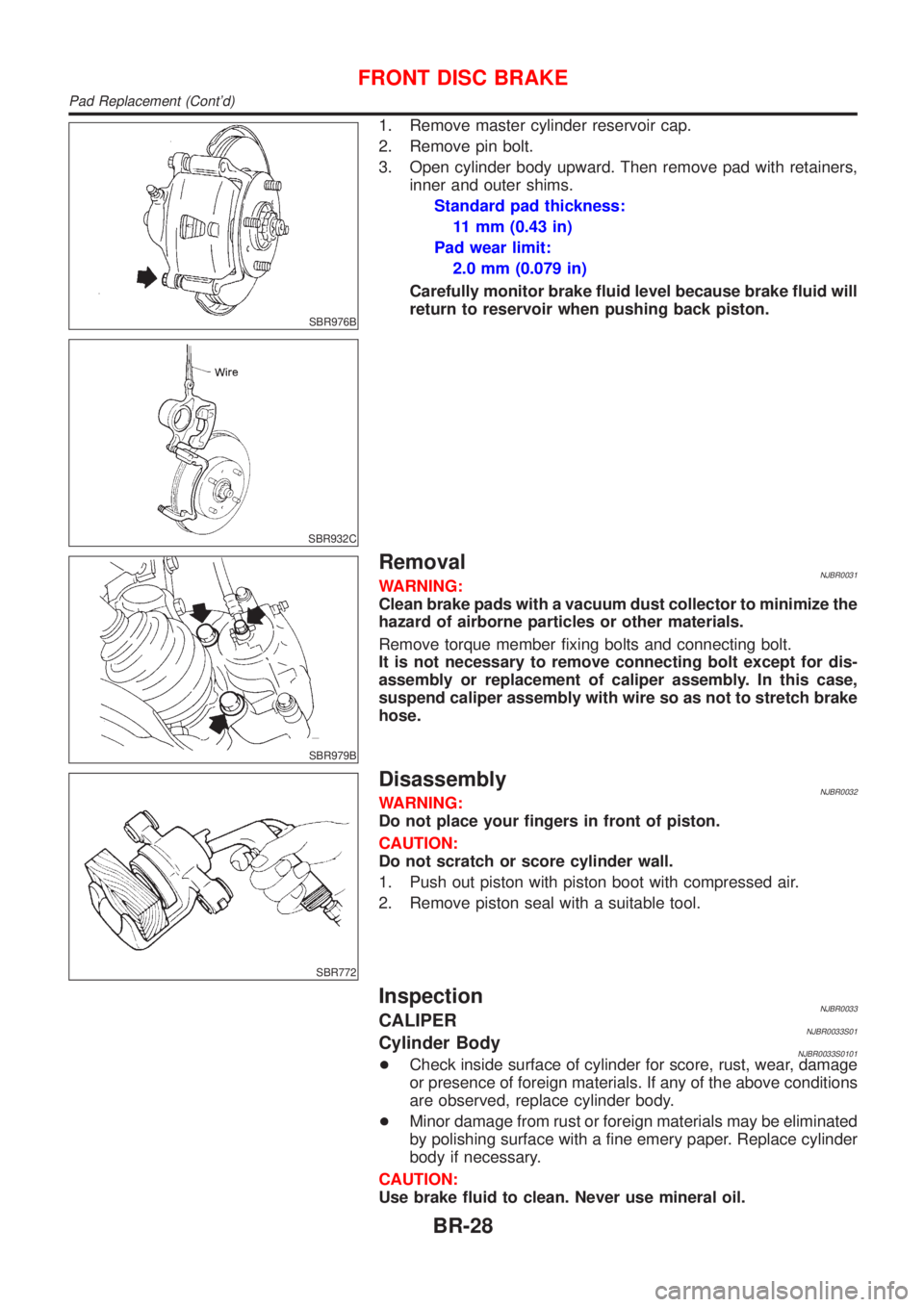
1. Remove master cylinder reservoir cap.
2. Remove pin bolt.
3. Open cylinder body upward. Then remove pad with retainers,
inner and outer shims.
Standard pad thickness:
11 mm (0.43 in)
Pad wear limit:
2.0 mm (0.079 in)
Carefully monitor brake fluid level because brake fluid will
return to reservoir when pushing back piston.
SBR979B
RemovalNJBR0031WARNING:
Clean brake pads with a vacuum dust collector to minimize the
hazard of airborne particles or other materials.
Remove torque member fixing bolts and connecting bolt.
It is not necessary to remove connecting bolt except for dis-
assembly or replacement of caliper assembly. In this case,
suspend caliper assembly with wire so as not to stretch brake
hose.
SBR772
DisassemblyNJBR0032WARNING:
Do not place your fingers in front of piston.
CAUTION:
Do not scratch or score cylinder wall.
1. Push out piston with piston boot with compressed air.
2. Remove piston seal with a suitable tool.
InspectionNJBR0033CALIPERNJBR0033S01Cylinder BodyNJBR0033S0101+Check inside surface of cylinder for score, rust, wear, damage
or presence of foreign materials. If any of the above conditions
are observed, replace cylinder body.
+Minor damage from rust or foreign materials may be eliminated
by polishing surface with a fine emery paper. Replace cylinder
body if necessary.
CAUTION:
Use brake fluid to clean. Never use mineral oil.
FRONT DISC BRAKE
Pad Replacement (Cont'd)
BR-28
Page 1727 of 2493
PistonNJBR0033S0102CAUTION:
Piston sliding surface is plated. Do not polish with emery
paper even if rust or foreign materials are stuck to sliding
surface.
Check piston for score, rust, wear, damage or presence of foreign
materials. Replace if any of the above conditions are observed.
Slide Pin, Pin Bolt and Pin BootNJBR0033S0103Check for wear, cracks or other damage. Replace if any of the
above conditions are observed.
ROTORNJBR0033S02Rubbing SurfaceNJBR0033S0201Check rotor for roughness, cracks or chips.
SBR219C
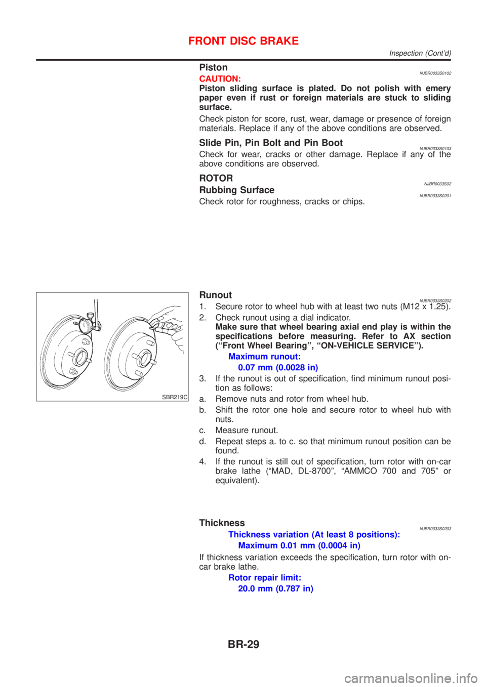
RunoutNJBR0033S02021. Secure rotor to wheel hub with at least two nuts (M12 x 1.25).
2. Check runout using a dial indicator.
Make sure that wheel bearing axial end play is within the
specifications before measuring. Refer to AX section
(ªFront Wheel Bearingº, ªON-VEHICLE SERVICEº).
Maximum runout:
0.07 mm (0.0028 in)
3. If the runout is out of specification, find minimum runout posi-
tion as follows:
a. Remove nuts and rotor from wheel hub.
b. Shift the rotor one hole and secure rotor to wheel hub with
nuts.
c. Measure runout.
d. Repeat steps a. to c. so that minimum runout position can be
found.
4. If the runout is still out of specification, turn rotor with on-car
brake lathe (ªMAD, DL-8700º, ªAMMCO 700 and 705º or
equivalent).
ThicknessNJBR0033S0203Thickness variation (At least 8 positions):
Maximum 0.01 mm (0.0004 in)
If thickness variation exceeds the specification, turn rotor with on-
car brake lathe.
Rotor repair limit:
20.0 mm (0.787 in)
FRONT DISC BRAKE
Inspection (Cont'd)
BR-29
Page 1737 of 2493
Pin and Pin BootNJBR0041S0104Check for wear, cracks or other damage.
Replace if any of the above conditions are observed.
SBR219C
ROTORNJBR0041S02Rubbing SurfaceNJBR0041S0201Check rotor for roughness, cracks or chips.
RunoutNJBR0041S02021. Secure rotor to wheel hub with two nuts (M12 x 1.25).
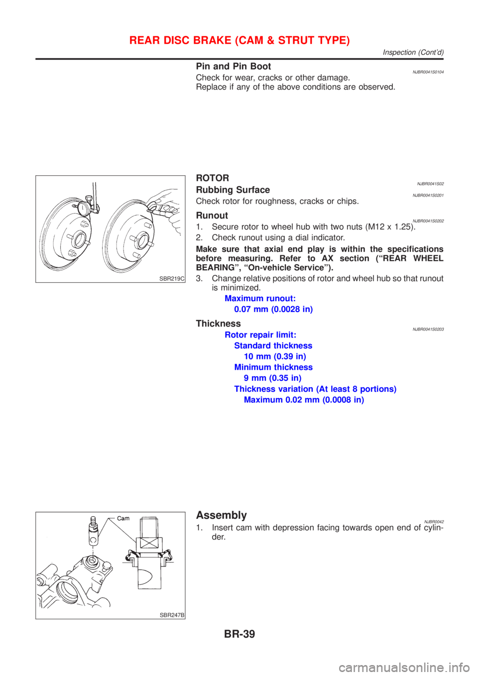
2. Check runout using a dial indicator.
Make sure that axial end play is within the specifications
before measuring. Refer to AX section (ªREAR WHEEL
BEARINGº, ªOn-vehicle Serviceº).
3. Change relative positions of rotor and wheel hub so that runout
is minimized.
Maximum runout:
0.07 mm (0.0028 in)
ThicknessNJBR0041S0203Rotor repair limit:
Standard thickness
10 mm (0.39 in)
Minimum thickness
9 mm (0.35 in)
Thickness variation (At least 8 portions)
Maximum 0.02 mm (0.0008 in)
SBR247B
AssemblyNJBR00421. Insert cam with depression facing towards open end of cylin-
der.
REAR DISC BRAKE (CAM & STRUT TYPE)
Inspection (Cont'd)
BR-39
Page 1743 of 2493
NBR427
RemovalNJBR0143WARNING:
Clean brake pads with a vacuum dust collector to minimize the
hazard of airborne particles or other materials.
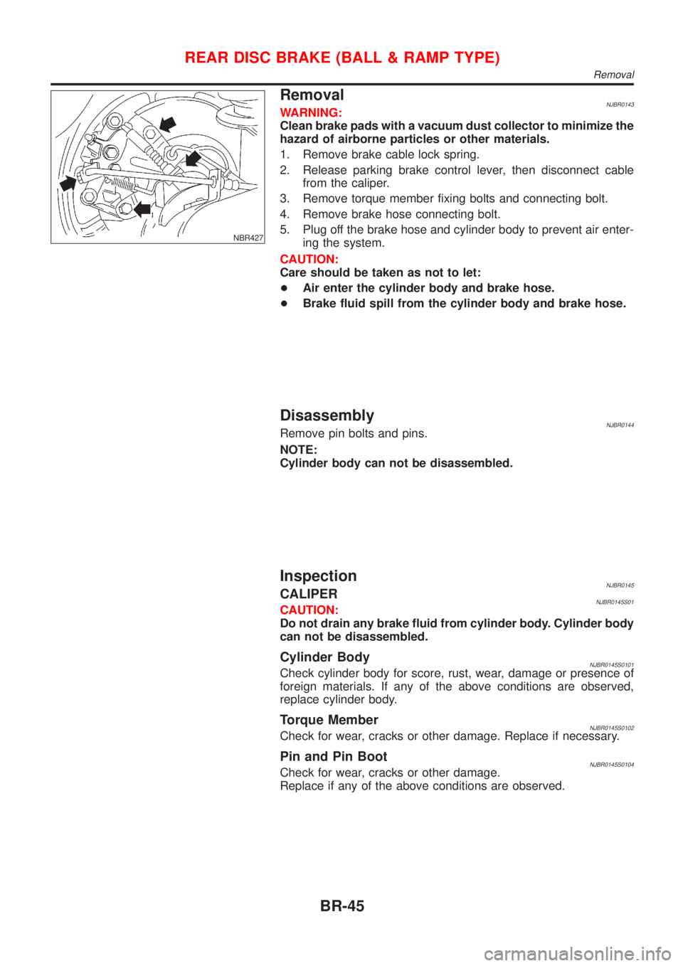
1. Remove brake cable lock spring.
2. Release parking brake control lever, then disconnect cable
from the caliper.
3. Remove torque member fixing bolts and connecting bolt.
4. Remove brake hose connecting bolt.
5. Plug off the brake hose and cylinder body to prevent air enter-
ing the system.
CAUTION:
Care should be taken as not to let:
+Air enter the cylinder body and brake hose.
+Brake fluid spill from the cylinder body and brake hose.
DisassemblyNJBR0144Remove pin bolts and pins.
NOTE:
Cylinder body can not be disassembled.
InspectionNJBR0145CALIPERNJBR0145S01CAUTION:
Do not drain any brake fluid from cylinder body. Cylinder body
can not be disassembled.
Cylinder BodyNJBR0145S0101Check cylinder body for score, rust, wear, damage or presence of
foreign materials. If any of the above conditions are observed,
replace cylinder body.
Torque MemberNJBR0145S0102Check for wear, cracks or other damage. Replace if necessary.
Pin and Pin BootNJBR0145S0104Check for wear, cracks or other damage.
Replace if any of the above conditions are observed.
REAR DISC BRAKE (BALL & RAMP TYPE)
Removal
BR-45
Page 1762 of 2493
SEF233G
SEF234G
How to Perform Trouble Diagnoses for Quick
and Accurate Repair
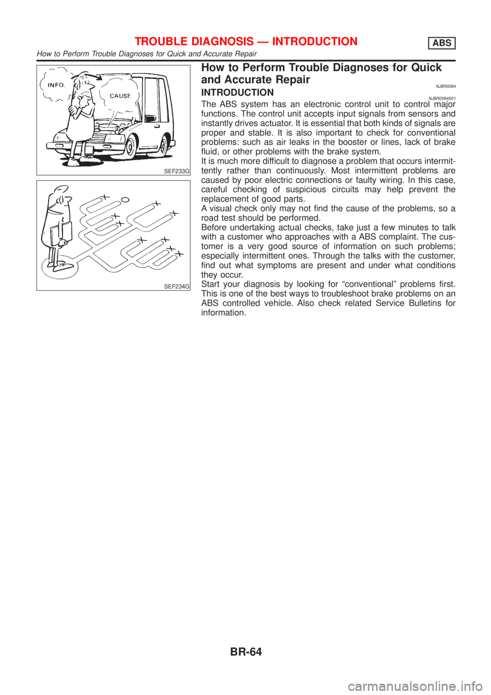
NJBR0094INTRODUCTIONNJBR0094S01The ABS system has an electronic control unit to control major
functions. The control unit accepts input signals from sensors and
instantly drives actuator. It is essential that both kinds of signals are
proper and stable. It is also important to check for conventional
problems: such as air leaks in the booster or lines, lack of brake
fluid, or other problems with the brake system.
It is much more difficult to diagnose a problem that occurs intermit-
tently rather than continuously. Most intermittent problems are
caused by poor electric connections or faulty wiring. In this case,
careful checking of suspicious circuits may help prevent the
replacement of good parts.
A visual check only may not find the cause of the problems, so a
road test should be performed.
Before undertaking actual checks, take just a few minutes to talk
with a customer who approaches with a ABS complaint. The cus-
tomer is a very good source of information on such problems;
especially intermittent ones. Through the talks with the customer,
find out what symptoms are present and under what conditions
they occur.
Start your diagnosis by looking for ªconventionalº problems first.
This is one of the best ways to troubleshoot brake problems on an
ABS controlled vehicle. Also check related Service Bulletins for
information.
TROUBLE DIAGNOSIS Ð INTRODUCTIONABS
How to Perform Trouble Diagnoses for Quick and Accurate Repair
BR-64
Page 1781 of 2493
5. Pedal Vibration and Noise=NJBR0108
1 INSPECTION START
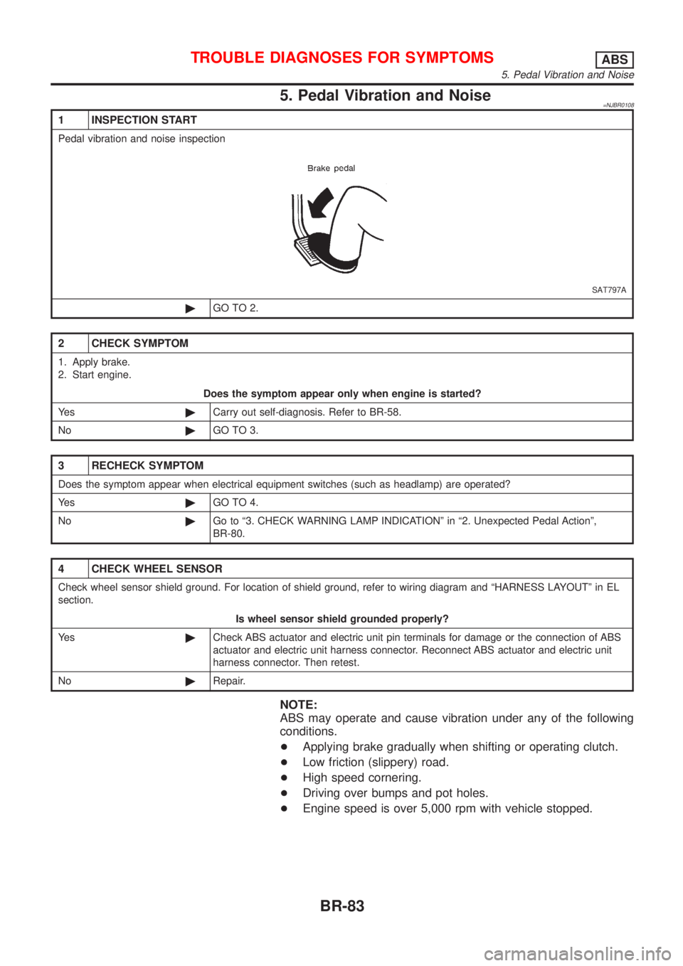
Pedal vibration and noise inspection
SAT797A
©GO TO 2.
2 CHECK SYMPTOM
1. Apply brake.
2. Start engine.
Does the symptom appear only when engine is started?
Ye s©Carry out self-diagnosis. Refer to BR-58.
No©GO TO 3.
3 RECHECK SYMPTOM
Does the symptom appear when electrical equipment switches (such as headlamp) are operated?
Ye s©GO TO 4.
No©Go to ª3. CHECK WARNING LAMP INDICATIONº in ª2. Unexpected Pedal Actionº,
BR-80.
4 CHECK WHEEL SENSOR
Check wheel sensor shield ground. For location of shield ground, refer to wiring diagram and ªHARNESS LAYOUTº in EL
section.
Is wheel sensor shield grounded properly?
Ye s©Check ABS actuator and electric unit pin terminals for damage or the connection of ABS
actuator and electric unit harness connector. Reconnect ABS actuator and electric unit
harness connector. Then retest.
No©Repair.
NOTE:
ABS may operate and cause vibration under any of the following
conditions.
+Applying brake gradually when shifting or operating clutch.
+Low friction (slippery) road.
+High speed cornering.
+Driving over bumps and pot holes.
+Engine speed is over 5,000 rpm with vehicle stopped.
TROUBLE DIAGNOSES FOR SYMPTOMSABS
5. Pedal Vibration and Noise
BR-83
Page 1808 of 2493
SST051C
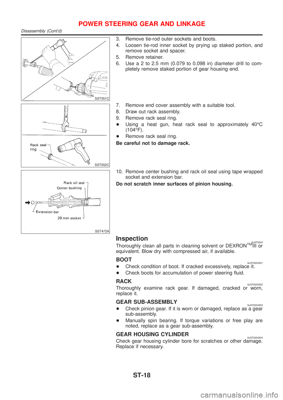
3. Remove tie-rod outer sockets and boots.
4. Loosen tie-rod inner socket by prying up staked portion, and
remove socket and spacer.
5. Remove retainer.
6. Usea2to2.5mm(0.079 to 0.098 in) diameter drill to com-
pletely remove staked portion of gear housing end.
SST052C
7. Remove end cover assembly with a suitable tool.
8. Draw out rack assembly.
9. Remove rack seal ring.
+Using a heat gun, heat rack seal to approximately 40ÉC
(104ÉF).
+Remove rack seal ring.
Be careful not to damage rack.
SST472A
10. Remove center bushing and rack oil seal using tape wrapped
socket and extension bar.
Do not scratch inner surfaces of pinion housing.
InspectionNJST0024Thoroughly clean all parts in cleaning solvent or DEXRONTMIII or
equivalent. Blow dry with compressed air, if available.
BOOTNJST0024S01+Check condition of boot. If cracked excessively, replace it.
+Check boots for accumulation of power steering fluid.
RACKNJST0024S02Thoroughly examine rack gear. If damaged, cracked or worn,
replace it.
GEAR SUB-ASSEMBLYNJST0024S03+Check pinion gear. If it is worn or damaged, replace as a gear
sub-assembly.
+Manually spin bearing. If torque variations or free play are
noted, replace as a gear sub-assembly.
GEAR HOUSING CYLINDERNJST0024S04Check gear housing cylinder bore for scratches or other damage.
Replace if necessary.
POWER STEERING GEAR AND LINKAGE
Disassembly (Cont'd)
ST-18
Page 1845 of 2493
SRS797-A
Maintenance ItemsNJRS0012CAUTION:
Do not use electrical test equipment to check SRS circuit.
1. Check operation of ªAIR BAGº warning lamp.
After turning ignition key to ªONº position, ªAIR BAGº warning
lamp illuminates. The ªAIR BAGº warning lamp will go off after
about 7 seconds if no malfunction is detected. If any of the fol-
lowing ªAIR BAGº warning lamp conditions occur, immediately
check the air bag system. Refer to RS-49 for details.
+The ªAIR BAGº warning lamp does not illuminate when the
ignition switch is turned ªONº.
+The ªAIR BAGº warning lamp does not go off about 7 seconds
after the ignition switch is turned ªONº.
+The ªAIR BAGº warning lamp blinks after about 7 seconds after
the ignition switch is turned ªONº.
2. Visually check SRS components.
1) Diagnosis sensor unit
+Check diagnosis sensor unit and bracket for dents, cracks and
deformities.
+Check connectors for damage, and terminals for deformities.
2) Air bag module and steering wheel
+Remove air bag module from steering wheel, instrument panel
or seatback. Check harness cover and connectors for damage,
terminals for deformities, and harness for binding.
+Install driver air bag module to steering wheel to check fit or
alignment with the wheel.
+Check steering wheel for excessive free play.
+Install front passenger air bag module to instrument panel to
check fit or alignment with the instrument panel.
+Install front side air bag module to seatback to check fit and
alignment with the seat.
3) Spiral cable
+Check spiral cable for dents, cracks, or deformities.
+Check connectors and protective tape for damage.
+Check steering wheel for noise, binding or heavy operation.
4) Main harness, body harness, side air bag module sub-harness
+Check connectors for poor connections, damage, and termi-
nals for deformities.
+Check harnesses for binding, chafing or cut.
5) Front seat belt pre-tensioner
+Check harness cover and connectors for damage, terminals
for deformities, and harness for binding.
+Check belts for damage and anchors for loose mounting.
+Check retractor for smooth operation.
+Perform self-diagnosis for seat belt pre-tensioner using ªAIR
BAGº warning lamp or CONSULT-II.
Refer to ªSRS Operation Checkº for details. (RS-49)
6) Side air bag (satellite) sensor
+Check side air bag (satellite) sensor (including bracket portion)
for dents, cracks or deformities.
+Check connectors for damage, and terminals for deformities.
CAUTION:
Replace previously used special bolts, hex bolts and ground
bolt with new ones.
SUPPLEMENTAL RESTRAINT SYSTEM (SRS)
Maintenance Items
RS-25