2001 NISSAN ALMERA N16 Air condition
[x] Cancel search: Air conditionPage 996 of 2493
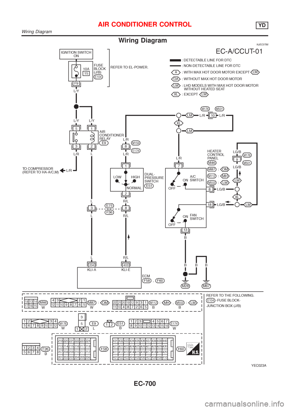
Wiring DiagramNJEC0786
YEC023A
AIR CONDITIONER CONTROLYD
Wiring Diagram
EC-700
Page 1189 of 2493
Diagnostic Procedure ..............................................253
Component Inspection .............................................255
DTC P1705 THROTTLE POSITION SENSOR...........256
Description ...............................................................256
Wiring Diagram - AT - TPS ......................................259
Diagnostic Procedure ..............................................260
Component Inspection .............................................264
DTC P1760 OVERRUN CLUTCH SOLENOID
VALVE..........................................................................265
Description ...............................................................265
Wiring Diagram - AT - OVRCSV..............................267
Diagnostic Procedure ..............................................268
Component Inspection .............................................270
DTC BATT/FLUID TEMP SEN (A/T FLUID TEMP
SENSOR CIRCUIT AND TCM POWER SOURCE)....271
Description ...............................................................271
Wiring Diagram - AT - BA/FTS ................................273
Diagnostic Procedure ..............................................274
Component Inspection .............................................277
DTC VHCL SPEED SEN.MTR VEHICLE SPEED......278
Description ...............................................................278
Wiring Diagram - AT - VSSMTR ..............................280
Diagnostic Procedure ..............................................281
DTC CONTROL UNIT (RAM), CONTROL UNIT
(ROM)...........................................................................282
Description ...............................................................282
Diagnostic Procedure ..............................................282
DTC CONTROL UNIT (EEP ROM).............................284
Description ...............................................................284
Diagnostic Procedure ..............................................285
TROUBLE DIAGNOSES FOR SYMPTOMS...............286
Wiring Diagram - AT - NONDTC .............................286
1. O/D OFF Indicator Lamp Does Not Come On....288
2. Engine Cannot Be Started In²P²and²N²
Position ....................................................................291
3. In²P²Position, Vehicle Moves Forward Or
Backward When Pushed .........................................292
4. In²N²Position, Vehicle Moves ...........................293
5. Large Shock.²N²->²R²Position .......................295
6. Vehicle Does Not Creep Backward In²R²
Position ....................................................................297
7. Vehicle Does Not Creep Forward In²D²,²2²
Or²1²Position .........................................................300
8. Vehicle Cannot Be Started From D
1...................303
9. A/T Does Not Shift: D
1-> D2Or Does Not
Kickdown: D
4-> D2..................................................306
10. A/T Does Not Shift: D
2-> D3.............................309
11. A/T Does Not Shift: D
3-> D4.............................312
12. A/T Does Not Perform Lock-up .........................315
13. A/T Does Not Hold Lock-up Condition ..............31714. Lock-up Is Not Released ...................................319
15. Engine Speed Does Not Return To Idle (Light
Braking D
4-> D3).....................................................320
16. Vehicle Does Not Start From D
1.......................322
17. A/T Does Not Shift: D
4-> D3, When
Overdrive Control Switch²ON²->²OFF²...............323
18. A/T Does Not Shift: D
3-> 22, When Selector
Lever²D²->²2²Position.........................................324
19. A/T Does Not Shift: 2
2-> 11, When Selector
Lever²2²->²1²Position .........................................325
20. Vehicle Does Not Decelerate By Engine
Brake........................................................................326
21. TCM Self-diagnosis Does Not Activate (PNP,
Overdrive Control and Throttle Position Switches
Circuit Checks) ........................................................326
A/T SHIFT LOCK SYSTEM.........................................335
Description ...............................................................335
Shift Lock System Electrical Parts Location............335
Wiring Diagram - SHIFT -........................................336
Diagnostic Procedure ..............................................337
KEY INTERLOCK CABLE..........................................341
Components.............................................................341
Removal ...................................................................341
Installation ................................................................342
ON-VEHICLE SERVICE..............................................343
Control Valve Assembly and Accumulators .............343
Control Cable Adjustment ........................................344
Park/Neutral Position (PNP) Switch Adjustment .....344
Differential Side Oil Seal Replacement ...................345
Revolution Sensor Replacement .............................345
REMOVAL AND INSTALLATION...............................346
Removal ...................................................................346
Installation ................................................................347
OVERHAUL.................................................................349
Components-1 .........................................................349
Components-2 .........................................................350
Components-3 .........................................................351
Oil Channel ..............................................................352
Locations of Adjusting Shims, Needle Bearings,
Thrust Washers and Snap Rings ............................353
DISASSEMBLY............................................................354
REPAIR FOR COMPONENT PARTS.........................368
Manual Shaft............................................................368
Oil Pump ..................................................................371
Control Valve Assembly ...........................................375
Control Valve Upper Body .......................................384
Control Valve Lower Body .......................................388
Reverse Clutch ........................................................390
High Clutch ..............................................................394
Forward Clutch and Overrun Clutch........................399
Low & Reverse Brake..............................................406
CONTENTS(Cont'd)
AT-3
Page 1201 of 2493
SMA827CA
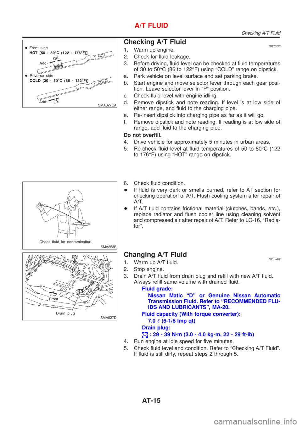
Checking A/T FluidNJAT02281. Warm up engine.
2. Check for fluid leakage.
3. Before driving, fluid level can be checked at fluid temperatures
of 30 to 50ÉC (86 to 122ÉF) using ªCOLDº range on dipstick.
a. Park vehicle on level surface and set parking brake.
b. Start engine and move selector lever through each gear posi-
tion. Leave selector lever in ªPº position.
c. Check fluid level with engine idling.
d. Remove dipstick and note reading. If level is at low side of
either range, and fluid to the charging pipe.
e. Re-insert dipstick into charging pipe as far as it will go.
f. Remove dipstick and note reading. If reading is at low side of
range, add fluid to the charging pipe.
Do not overfill.
4. Drive vehicle for approximately 5 minutes in urban areas.
5. Re-check fluid level at fluid temperatures of 50 to 80ÉC (122
to 176ÉF) using ªHOTº range on dipstick.
SMA853B
6. Check fluid condition.
+If fluid is very dark or smells burned, refer to AT section for
checking operation of A/T. Flush cooling system after repair of
A/T.
+If A/T fluid contains frictional material (clutches, bands, etc.),
replace radiator and flush cooler line using cleaning solvent
and compressed air after repair of A/T. Refer to LC-16, ªRadia-
torº.
SMA027D
Changing A/T FluidNJAT02291. Warm up A/T fluid.
2. Stop engine.
3. Drain A/T fluid from drain plug and refill with new A/T fluid.
Always refill same volume with drained fluid.
Fluid grade:
Nissan Matic ªDº or Genuine Nissan Automatic
Transmission Fluid. Refer to ªRECOMMENDED FLU-
IDS AND LUBRICANTSº, MA-20.
Fluid capacity (With torque converter):
7.0!(6-1/8 Imp qt)
Drain plug:
: 29 - 39 N´m (3.0 - 4.0 kg-m, 22 - 29 ft-lb)
4. Run engine at idle speed for five minutes.
5. Check fluid level and condition. Refer to ªChecking A/T Fluidº.
If fluid is still dirty, repeat steps 2 through 5.
A/T FLUID
Checking A/T Fluid
AT-15
Page 1256 of 2493
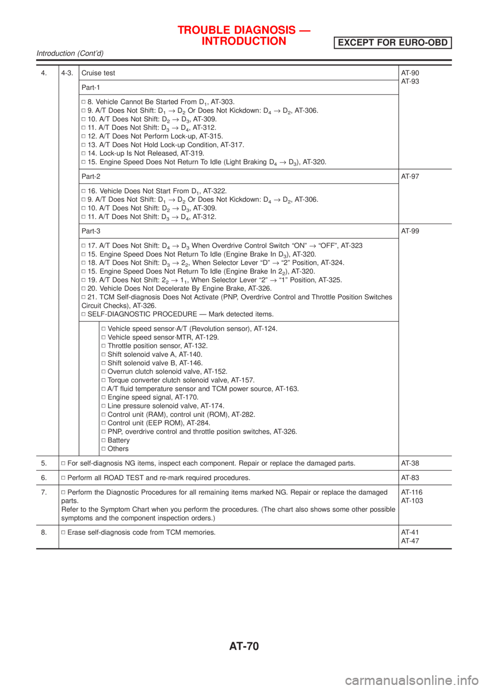
4. 4-3. Cruise testAT-90
AT-93
Part-1
N8. Vehicle Cannot Be Started From D
1, AT-303.
N9. A/T Does Not Shift: D
1®D2Or Does Not Kickdown: D4®D2, AT-306.
N10. A/T Does Not Shift: D
2®D3, AT-309.
N11. A/T Does Not Shift: D
3®D4, AT-312.
N12. A/T Does Not Perform Lock-up, AT-315.
N13. A/T Does Not Hold Lock-up Condition, AT-317.
N14. Lock-up Is Not Released, AT-319.
N15. Engine Speed Does Not Return To Idle (Light Braking D
4®D3), AT-320.
Part-2AT-97
N16. Vehicle Does Not Start From D
1, AT-322.
N9. A/T Does Not Shift: D
1®D2Or Does Not Kickdown: D4®D2, AT-306.
N10. A/T Does Not Shift: D
2®D3, AT-309.
N11. A/T Does Not Shift: D
3®D4, AT-312.
Part-3AT-99
N17. A/T Does Not Shift: D
4®D3When Overdrive Control Switch ªONº®ªOFFº, AT-323
N15. Engine Speed Does Not Return To Idle (Engine Brake In D
3), AT-320.
N18. A/T Does Not Shift: D
3®22, When Selector Lever ªDº®ª2º Position, AT-324.
N15. Engine Speed Does Not Return To Idle (Engine Brake In 2
2), AT-320.
N19. A/T Does Not Shift: 2
2®11, When Selector Lever ª2º®ª1º Position, AT-325.
N20. Vehicle Does Not Decelerate By Engine Brake, AT-326.
N21. TCM Self-diagnosis Does Not Activate (PNP, Overdrive Control and Throttle Position Switches
Circuit Checks), AT-326.
NSELF-DIAGNOSTIC PROCEDURE Ð Mark detected items.
NVehicle speed sensor´A/T (Revolution sensor), AT-124.
NVehicle speed sensor´MTR, AT-129.
NThrottle position sensor, AT-132.
NShift solenoid valve A, AT-140.
NShift solenoid valve B, AT-146.
NOverrun clutch solenoid valve, AT-152.
NTorque converter clutch solenoid valve, AT-157.
NA/T fluid temperature sensor and TCM power source, AT-163.
NEngine speed signal, AT-170.
NLine pressure solenoid valve, AT-174.
NControl unit (RAM), control unit (ROM), AT-282.
NControl unit (EEP ROM), AT-284.
NPNP, overdrive control and throttle position switches, AT-326.
NBattery
NOthers
5.NFor self-diagnosis NG items, inspect each component. Repair or replace the damaged parts. AT-38
6.NPerform all ROAD TEST and re-mark required procedures. AT-83
7.NPerform the Diagnostic Procedures for all remaining items marked NG. Repair or replace the damaged
parts.
Refer to the Symptom Chart when you perform the procedures. (The chart also shows some other possible
symptoms and the component inspection orders.)AT-116
AT-103
8.NErase self-diagnosis code from TCM memories. AT-41
AT-47
TROUBLE DIAGNOSIS Ð
INTRODUCTION
EXCEPT FOR EURO-OBD
Introduction (Cont'd)
AT-70
Page 1257 of 2493
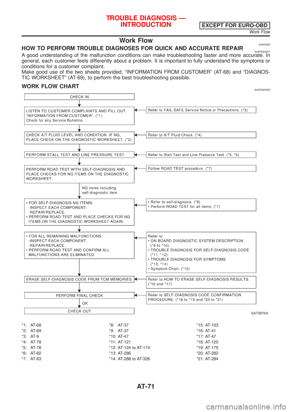
Work FlowNJAT0024HOW TO PERFORM TROUBLE DIAGNOSES FOR QUICK AND ACCURATE REPAIRNJAT0024S01A good understanding of the malfunction conditions can make troubleshooting faster and more accurate. In
general, each customer feels differently about a problem. It is important to fully understand the symptoms or
conditions for a customer complaint.
Make good use of the two sheets provided, ªINFORMATION FROM CUSTOMERº (AT-68) and ªDIAGNOS-
TIC WORKSHEETº (AT-69), to perform the best troubleshooting possible.
WORK FLOW CHARTNJAT0024S02
SAT097KA
*1: AT-68
*2: AT-69
*3: AT-9
*4: AT-78
*5: AT-78
*6: AT-82
*7: AT-83*8: AT-37
*9: AT-37
*10: AT-47
*11: AT-121
*12: AT-124 to AT-174
*13: AT-286
*14: AT-288 to AT-326*15: AT-103
*16: AT-41
*17: AT-47
*18: AT-125
*19: AT-175
*20: AT-282
*21: AT-284
TROUBLE DIAGNOSIS Ð
INTRODUCTION
EXCEPT FOR EURO-OBD
Work Flow
AT-71
Page 1261 of 2493
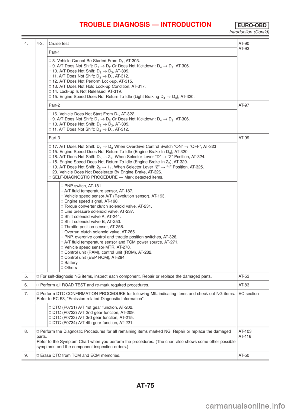
4. 4-3. Cruise testAT-90
AT-93
Part-1
N8. Vehicle Cannot Be Started From D
1, AT-303.
N9. A/T Does Not Shift: D
1®D2Or Does Not Kickdown: D4®D2, AT-306.
N10. A/T Does Not Shift: D
2®D3, AT-309.
N11. A/T Does Not Shift: D
3®D4, AT-312.
N12. A/T Does Not Perform Lock-up, AT-315.
N13. A/T Does Not Hold Lock-up Condition, AT-317.
N14. Lock-up Is Not Released, AT-319.
N15. Engine Speed Does Not Return To Idle (Light Braking D
4®D3), AT-320.
Part-2AT-97
N16. Vehicle Does Not Start From D
1, AT-322.
N9. A/T Does Not Shift: D
1®D2Or Does Not Kickdown: D4®D2, AT-306.
N10. A/T Does Not Shift: D
2®D3, AT-309.
N11. A/T Does Not Shift: D
3®D4, AT-312.
Part-3AT-99
N17. A/T Does Not Shift: D
4®D3When Overdrive Control Switch ªONº®ªOFFº, AT-323
N15. Engine Speed Does Not Return To Idle (Engine Brake In D
3), AT-320.
N18. A/T Does Not Shift: D
3®22, When Selector Lever ªDº®ª2º Position, AT-324.
N15. Engine Speed Does Not Return To Idle (Engine Brake In 2
2), AT-320.
N19. A/T Does Not Shift: 2
2®11, When Selector Lever ª2º®ª1º Position, AT-325.
N20. Vehicle Does Not Decelerate By Engine Brake, AT-326.
NSELF-DIAGNOSTIC PROCEDURE Ð Mark detected items.
NPNP switch, AT-181.
NA/T fluid temperature sensor, AT-187.
NVehicle speed sensor´A/T (Revolution sensor), AT-193.
NEngine speed signal, AT-198.
NTorque converter clutch solenoid valve, AT-231.
NLine pressure solenoid valve, AT-237.
NShift solenoid valve A, AT-244.
NShift solenoid valve B, AT-250.
NThrottle position sensor, AT-256.
NOverrun clutch solenoid valve, AT-265.
NPNP, overdrive control and throttle position switches, AT-326.
NA/T fluid temperature sensor and TCM power source, AT-271.
NVehicle speed sensor´MTR, AT-278.
NControl unit (RAM), control unit (ROM), AT-282.
NControl unit (EEP ROM), AT-284.
NBattery
NOthers
5.NFor self-diagnosis NG items, inspect each component. Repair or replace the damaged parts. AT-53
6.NPerform all ROAD TEST and re-mark required procedures. AT-83
7.NPerform DTC CONFIRMATION PROCEDURE for following MIL indicating items and check out NG items.
Refer to EC-58, ªEmission-related Diagnostic Informationº.EC section
NDTC (P0731) A/T 1st gear function, AT-202.
NDTC (P0732) A/T 2nd gear function, AT-209.
NDTC (P0733) A/T 3rd gear function, AT-215.
NDTC (P0734) A/T 4th gear function, AT-221.
8.NPerform the Diagnostic Procedures for all remaining items marked NG. Repair or replace the damaged
parts.
Refer to the Symptom Chart when you perform the procedures. (The chart also shows some other possible
symptoms and the component inspection orders.)AT-103
AT-116
9.NErase DTC from TCM and ECM memories. AT-50
TROUBLE DIAGNOSIS Ð INTRODUCTIONEURO-OBD
Introduction (Cont'd)
AT-75
Page 1262 of 2493
Work FlowNJAT0258HOW TO PERFORM TROUBLE DIAGNOSES FOR QUICK AND ACCURATE REPAIRNJAT0258S01A good understanding of the malfunction conditions can make troubleshooting faster and more accurate. In
general, each customer feels differently about a problem. It is important to fully understand the symptoms or
conditions for a customer complaint.
Make good use of the two sheets provided, ªINFORMATION FROM CUSTOMERº (AT-73) and ªDIAGNOS-
TIC WORKSHEETº (AT-74), to perform the best troubleshooting possible.
TROUBLE DIAGNOSIS Ð INTRODUCTIONEURO-OBD
Work Flow
AT-76
Page 1311 of 2493
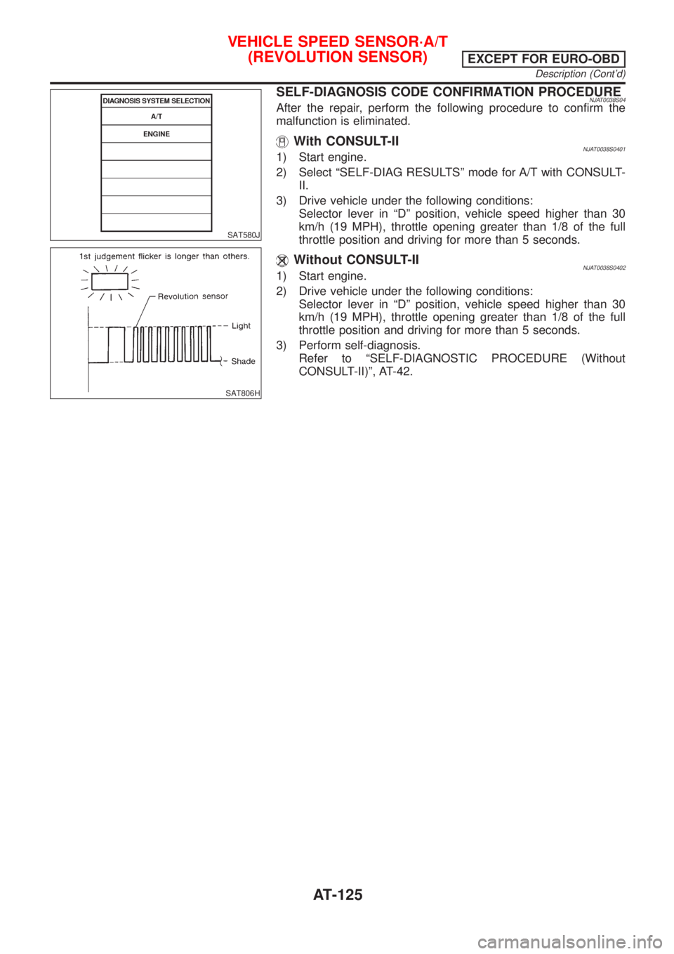
SAT580J
SAT806H
SELF-DIAGNOSIS CODE CONFIRMATION PROCEDURENJAT0038S04After the repair, perform the following procedure to confirm the
malfunction is eliminated.
With CONSULT-IINJAT0038S04011) Start engine.
2) Select ªSELF-DIAG RESULTSº mode for A/T with CONSULT-
II.
3) Drive vehicle under the following conditions:
Selector lever in ªDº position, vehicle speed higher than 30
km/h (19 MPH), throttle opening greater than 1/8 of the full
throttle position and driving for more than 5 seconds.
Without CONSULT-IINJAT0038S04021) Start engine.
2) Drive vehicle under the following conditions:
Selector lever in ªDº position, vehicle speed higher than 30
km/h (19 MPH), throttle opening greater than 1/8 of the full
throttle position and driving for more than 5 seconds.
3) Perform self-diagnosis.
Refer to ªSELF-DIAGNOSTIC PROCEDURE (Without
CONSULT-II)º, AT-42.
VEHICLE SPEED SENSOR´A/T
(REVOLUTION SENSOR)
EXCEPT FOR EURO-OBD
Description (Cont'd)
AT-125