2001 NISSAN ALMERA N16 Air condition
[x] Cancel search: Air conditionPage 1864 of 2493
How to Perform Trouble Diagnoses for Quick
and Accurate Repair
=NJRS0044A good understanding of the malfunction conditions can make troubleshooting faster and more accurate.
In general, each customer feels differently about a malfunction. It is important to fully understand the symp-
toms or conditions for a customer complaint.
INFORMATION FROM CUSTOMERNJRS0044S01WHAT ..... Vehicle model
WHEN ..... Date, Frequencies
WHERE ..... Road conditions
HOW ..... Operating conditions, Symptoms
PRELIMINARY CHECKNJRS0044S02Check that the following parts are in good order.
+Battery [Refer to SC-3, ªBATTERYº.]
+Fuse [Refer to EL-22, ªFuseº, ªPOWER SUPPLY ROUTINGº.]
+System component-to-harness connections
SUPPLEMENTAL RESTRAINT SYSTEM (SRS)
How to Perform Trouble Diagnoses for Quick and Accurate Repair
RS-44
Page 1869 of 2493
SRS800
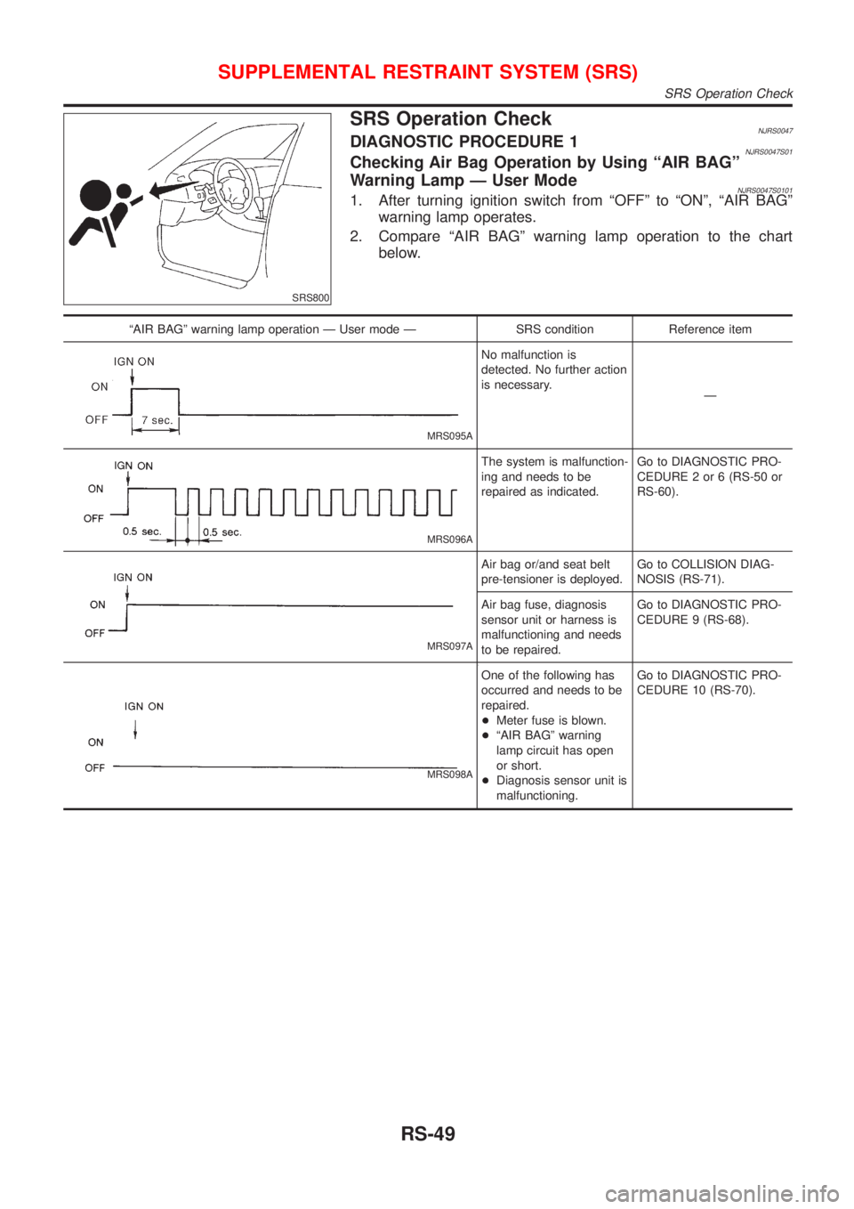
SRS Operation CheckNJRS0047DIAGNOSTIC PROCEDURE 1NJRS0047S01Checking Air Bag Operation by Using ªAIR BAGº
Warning Lamp Ð User Mode
NJRS0047S01011. After turning ignition switch from ªOFFº to ªONº, ªAIR BAGº
warning lamp operates.
2. Compare ªAIR BAGº warning lamp operation to the chart
below.
ªAIR BAGº warning lamp operation Ð User mode Ð SRS condition Reference item
MRS095A
No malfunction is
detected. No further action
is necessary.
Ð
MRS096A
The system is malfunction-
ing and needs to be
repaired as indicated.Go to DIAGNOSTIC PRO-
CEDURE 2 or 6 (RS-50 or
RS-60).
MRS097A
Air bag or/and seat belt
pre-tensioner is deployed.Go to COLLISION DIAG-
NOSIS (RS-71).
Air bag fuse, diagnosis
sensor unit or harness is
malfunctioning and needs
to be repaired.Go to DIAGNOSTIC PRO-
CEDURE 9 (RS-68).
MRS098A
One of the following has
occurred and needs to be
repaired.
+Meter fuse is blown.
+ªAIR BAGº warning
lamp circuit has open
or short.
+Diagnosis sensor unit is
malfunctioning.Go to DIAGNOSTIC PRO-
CEDURE 10 (RS-70).
SUPPLEMENTAL RESTRAINT SYSTEM (SRS)
SRS Operation Check
RS-49
Page 1881 of 2493
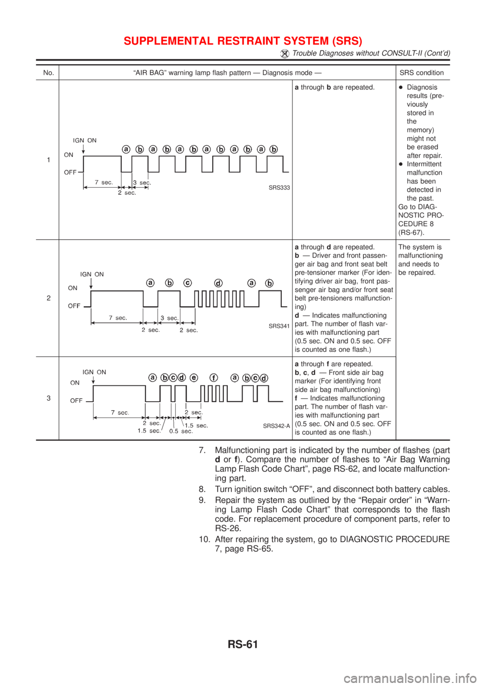
No. ªAIR BAGº warning lamp flash pattern Ð Diagnosis mode Ð SRS condition
1
SRS333
athroughbare repeated.+Diagnosis
results (pre-
viously
stored in
the
memory)
might not
be erased
after repair.
+Intermittent
malfunction
has been
detected in
the past.
Go to DIAG-
NOSTIC PRO-
CEDURE 8
(RS-67).
2
SRS341
athroughdare repeated.
bÐ Driver and front passen-
ger air bag and front seat belt
pre-tensioner marker (For iden-
tifying driver air bag, front pas-
senger air bag and/or front seat
belt pre-tensioners malfunction-
ing)
dÐ Indicates malfunctioning
part. The number of flash var-
ies with malfunctioning part
(0.5 sec. ON and 0.5 sec. OFF
is counted as one flash.)The system is
malfunctioning
and needs to
be repaired.
3
SRS342-A
athroughfare repeated.
b,c,dÐ Front side air bag
marker (For identifying front
side air bag malfunctioning)
fÐ Indicates malfunctioning
part. The number of flash var-
ies with malfunctioning part
(0.5 sec. ON and 0.5 sec. OFF
is counted as one flash.)
7. Malfunctioning part is indicated by the number of flashes (part
dorf). Compare the number of flashes to ªAir Bag Warning
Lamp Flash Code Chartº, page RS-62, and locate malfunction-
ing part.
8. Turn ignition switch ªOFFº, and disconnect both battery cables.
9. Repair the system as outlined by the ªRepair orderº in ªWarn-
ing Lamp Flash Code Chartº that corresponds to the flash
code. For replacement procedure of component parts, refer to
RS-26.
10. After repairing the system, go to DIAGNOSTIC PROCEDURE
7, page RS-65.
SUPPLEMENTAL RESTRAINT SYSTEM (SRS)
Trouble Diagnoses without CONSULT-II (Cont'd)
RS-61
Page 1886 of 2493
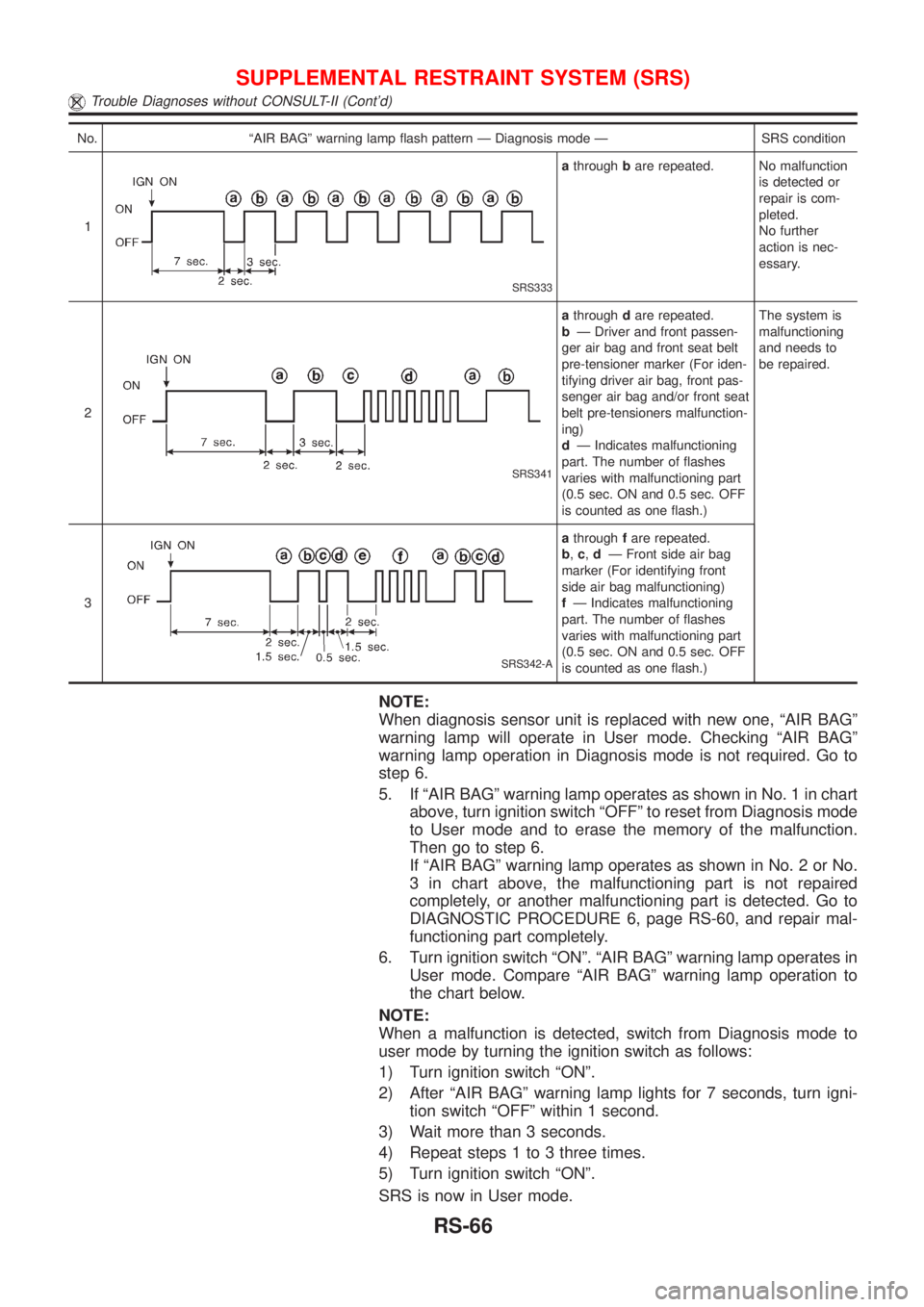
No. ªAIR BAGº warning lamp flash pattern Ð Diagnosis mode Ð SRS condition
1
SRS333
athroughbare repeated. No malfunction
is detected or
repair is com-
pleted.
No further
action is nec-
essary.
2
SRS341
athroughdare repeated.
bÐ Driver and front passen-
ger air bag and front seat belt
pre-tensioner marker (For iden-
tifying driver air bag, front pas-
senger air bag and/or front seat
belt pre-tensioners malfunction-
ing)
dÐ Indicates malfunctioning
part. The number of flashes
varies with malfunctioning part
(0.5 sec. ON and 0.5 sec. OFF
is counted as one flash.)The system is
malfunctioning
and needs to
be repaired.
3
SRS342-A
athroughfare repeated.
b,c,dÐ Front side air bag
marker (For identifying front
side air bag malfunctioning)
fÐ Indicates malfunctioning
part. The number of flashes
varies with malfunctioning part
(0.5 sec. ON and 0.5 sec. OFF
is counted as one flash.)
NOTE:
When diagnosis sensor unit is replaced with new one, ªAIR BAGº
warning lamp will operate in User mode. Checking ªAIR BAGº
warning lamp operation in Diagnosis mode is not required. Go to
step 6.
5. If ªAIR BAGº warning lamp operates as shown in No. 1 in chart
above, turn ignition switch ªOFFº to reset from Diagnosis mode
to User mode and to erase the memory of the malfunction.
Then go to step 6.
If ªAIR BAGº warning lamp operates as shown in No. 2 or No.
3 in chart above, the malfunctioning part is not repaired
completely, or another malfunctioning part is detected. Go to
DIAGNOSTIC PROCEDURE 6, page RS-60, and repair mal-
functioning part completely.
6. Turn ignition switch ªONº. ªAIR BAGº warning lamp operates in
User mode. Compare ªAIR BAGº warning lamp operation to
the chart below.
NOTE:
When a malfunction is detected, switch from Diagnosis mode to
user mode by turning the ignition switch as follows:
1) Turn ignition switch ªONº.
2) After ªAIR BAGº warning lamp lights for 7 seconds, turn igni-
tion switch ªOFFº within 1 second.
3) Wait more than 3 seconds.
4) Repeat steps 1 to 3 three times.
5) Turn ignition switch ªONº.
SRS is now in User mode.
SUPPLEMENTAL RESTRAINT SYSTEM (SRS)
Trouble Diagnoses without CONSULT-II (Cont'd)
RS-66
Page 1887 of 2493
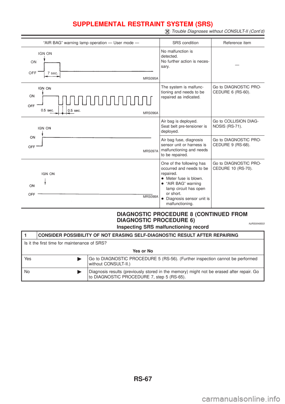
ªAIR BAGº warning lamp operation Ð User mode Ð SRS condition Reference item
MRS095A
No malfunction is
detected.
No further action is neces-
sary.Ð
MRS096A
The system is malfunc-
tioning and needs to be
repaired as indicated.Go to DIAGNOSTIC PRO-
CEDURE 6 (RS-60).
MRS097A
Air bag is deployed.
Seat belt pre-tensioner is
deployed.Go to COLLISION DIAG-
NOSIS (RS-71).
Air bag fuse, diagnosis
sensor unit or harness is
malfunctioning and needs
to be repaired.Go to DIAGNOSTIC PRO-
CEDURE 9 (RS-68).
MRS098A
One of the following has
occurred and needs to be
repaired.
+Meter fuse is blown.
+ªAIR BAGº warning
lamp circuit has open
or short.
+Diagnosis sensor unit is
malfunctioning.Go to DIAGNOSTIC PRO-
CEDURE 10 (RS-70).
DIAGNOSTIC PROCEDURE 8 (CONTINUED FROM
DIAGNOSTIC PROCEDURE 6)
NJRS0049S03Inspecting SRS malfunctioning record
1 CONSIDER POSSIBILITY OF NOT ERASING SELF-DIAGNOSTIC RESULT AFTER REPAIRING
Is it the first time for maintenance of SRS?
YesorNo
Ye s©Go to DIAGNOSTIC PROCEDURE 5 (RS-56). (Further inspection cannot be performed
without CONSULT-II.)
No©Diagnosis results (previously stored in the memory) might not be erased after repair. Go
to DIAGNOSTIC PROCEDURE 7, step 5 (RS-65).
SUPPLEMENTAL RESTRAINT SYSTEM (SRS)
Trouble Diagnoses without CONSULT-II (Cont'd)
RS-67
Page 1900 of 2493
Checking Body CorrosionNJBT0033Visually check the body sheet metal panel for corrosion, paint damage (scratches, chipping, rubbing, etc.) or
damage to the anti-corrosion materials. In particular, check the following locations.
Hemmed portion
Hood front end, door lower end, trunk lid rear end, etc.
Panel joint
Side sill of rear fender and center pillar, rear wheel housing of rear fender, around strut tower in engine
compartment, etc.
Panel edge
Trunk lid opening, sunroof opening, fender wheelarch flange, fuel filler lid flange, around holes in panel, etc.
Parts contact
Waist molding, windshield molding, bumper, etc.
Protectors
Damage or condition of mudguard, fender protector, chipping protector, etc.
Anti-corrosion materials
Damage or separation of anti-corrosion materials under the body.
Drain holes
Condition of drain holes at door and side sill.
When repairing corroded areas, refer to the Corrosion Repair Manual.
CHASSIS AND BODY MAINTENANCE
Checking Body Corrosion
BT-6
Page 1973 of 2493
HEATER &
AIR CONDITIONER
SECTION
HA
CONTENTS
PRECAUTIONS...............................................................2
Supplemental Restraint System (SRS)²AIR
BAG²and²SEAT BELT PRE-TENSIONER²...............2
Precautions for Working with HFC-134a (R-134a) .....2
General Refrigerant Precautions .................................2
Precautions for Refrigerant Connection ......................3
Precautions for Servicing Compressor ........................5
Precautions for Service Equipment .............................6
Wiring Diagrams and Trouble Diagnosis .....................8
PREPARATION...............................................................9
Special Service Tools ..................................................9
HFC-134a (R-134a) Service Tools and
Equipment .................................................................. 11
DESCRIPTION...............................................................13
Refrigeration System .................................................13
CSV613 Variable Displacement Compressor............14
Component Layout ....................................................18
Control Operation ......................................................19
Discharge Air Flow.....................................................20
System Description ....................................................21
TROUBLE DIAGNOSES................................................22
Component Location..................................................22
Wiring Diagram - Heater............................................24
Circuit Diagram - Air Conditioner...............................26
Wiring Diagram - A/C, M - .........................................27
How to Perform Trouble Diagnoses for Quick
and Accurate Repair ..................................................39
Operational Check .....................................................40
Intake Door ................................................................42
Mode Door .................................................................46Air Mix Door ...............................................................48
Max Hot Door (For Scandinavia and Cold Spec
Models) ......................................................................50
Blower Motor..............................................................54
Magnet Clutch............................................................61
Insufficient Cooling ....................................................74
Insufficient Heating ....................................................82
Noise ..........................................................................83
SERVICE PROCEDURE................................................84
HFC-134a (R-134a) Service Procedure ....................84
Maintenance of Lubricant Quantity in
Compressor ...............................................................86
Compressor ...............................................................89
Compressor Clutch - CSV613 (CALSONIC
make) .........................................................................90
Heater & Cooling Unit (Heater Core) ........................94
A/C Evaporator ..........................................................94
Blower Unit ................................................................95
Refrigerant Lines .......................................................97
Belt ...........................................................................101
Idle Air Control Valve (IACV) - Auxiliary Air
Control (AAC) Valve ................................................102
Ventilation Air Filter ..................................................102
SERVICE DATA AND SPECIFICATIONS (SDS).......103
Compressor .............................................................103
Lubricant ..................................................................103
Refrigerant ...............................................................103
Engine Idling Speed (When A/C is On)...................103
Belt Tension .............................................................103
Page 1974 of 2493
Supplemental Restraint System (SRS) ªAIR
BAGº and ªSEAT BELT PRE-TENSIONERº
NJHA0190The Supplemental Restraint System such as ªAIR BAGº and ªSEAT BELT PRE-TENSIONERº used along with
a seat belt, helps to reduce the risk or severity of injury to the driver and front passenger for certain types of
collision. The SRS system composition which is available to NISSAN MODEL N16 is as follows (The compo-
sition varies according to the destination and optional equipment.):
+For a frontal collision
The Supplemental Restraint System consists of driver air bag module (located in the center of the steer-
ing wheel), front passenger air bag module (located on the instrument panel on passenger side), front seat
belt pre-tensioners, a diagnosis sensor unit, warning lamp, wiring harness and spiral cable.
+For a side collision
The Supplemental Restraint System consists of front side air bag module (located in the outer side of front
seat), side air bag (satellite) sensor, diagnosis sensor unit (one of components of air bags for a frontal
collision), wiring harness, warning lamp (one of components of air bags for a frontal collision).
Information necessary to service the system safely is included in theRS sectionof this Service Manual.
WARNING:
+To avoid rendering the SRS inoperative, which could increase the risk of personal injury or death
in the event of a collision which would result in air bag inflation, all maintenance should be per-
formed by an authorized NISSAN dealer.
+Improper maintenance, including incorrect removal and installation of the SRS, can lead to per-
sonal injury caused by unintentional activation of the system. For removal of Spiral Cable and Air
Bag Module, see the RS section.
+Do not use electrical test equipment on any circuit related to the SRS unless instructed to in this
Service Manual. Spiral cable and wiring harnesses covered with yellow insulation tape either just
before the harness connectors or for the complete harness are related to the SRS.
Precautions for Working with HFC-134a
(R-134a)
NJHA0113WARNING:
+CFC-12 (R-12) refrigerant and HFC-134a (R-134a) refrigerant are not compatible. These refrigerants
must never be mixed, even in the smallest amounts. If the refrigerants are mixed, compressor fail-
ure is likely to occur.
+Use only specified lubricant for the HFC-134a (R-134a) A/C system and HFC-134a (R-134a) compo-
nents. If lubricant other than that specified is used, compressor failure is likely to occur.
+The specified HFC-134a (R-134a) lubricant rapidly absorbs moisture from the atmosphere. The fol-
lowing handling precautions must be observed:
a) When removing refrigerant components from a vehicle, immediately cap (seal) the component to
minimize the entry of moisture from the atmosphere.
b) When installing refrigerant components to a vehicle, do not remove the caps (unseal) until just
before connecting the components. Connect all refrigerant loop components as quickly as pos-
sible to minimize the entry of moisture into system.
c) Only use the specified lubricant from a sealed container. Immediately reseal containers of lubri-
cant. Without proper sealing, lubricant will become moisture saturated and should not be used.
d) Avoid breathing A/C refrigerant and lubricant vapor or mist. Exposure may irritate eyes, nose
and throat. Remove R-134a from the A/C system, using certified service equipment meeting
requirements of R-134a recycling equipment, or R-134a recovery equipment. If accidental system
discharge occurs, ventilate work area before resuming service. Additional health and safety
information may be obtained from refrigerant and lubricant manufacturers.
e) Do not allow lubricant (Nissan A/C System Oil Type S) to come in contact with styrofoam parts.
Damage may result.
General Refrigerant PrecautionsNJHA0114WARNING:
+Do not release refrigerant into the air. Use approved recovery/recycling equipment to capture the
refrigerant every time an air conditioning system is discharged.
+Always wear eye and hand protection (goggles and gloves) when working with any refrigerant or
air conditioning system.
PRECAUTIONS
Supplemental Restraint System (SRS) ªAIR BAGº and ªSEAT BELT PRE-TENSIONERº
HA-2