2001 NISSAN ALMERA N16 washer fluid
[x] Cancel search: washer fluidPage 1189 of 2493
Diagnostic Procedure ..............................................253
Component Inspection .............................................255
DTC P1705 THROTTLE POSITION SENSOR...........256
Description ...............................................................256
Wiring Diagram - AT - TPS ......................................259
Diagnostic Procedure ..............................................260
Component Inspection .............................................264
DTC P1760 OVERRUN CLUTCH SOLENOID
VALVE..........................................................................265
Description ...............................................................265
Wiring Diagram - AT - OVRCSV..............................267
Diagnostic Procedure ..............................................268
Component Inspection .............................................270
DTC BATT/FLUID TEMP SEN (A/T FLUID TEMP
SENSOR CIRCUIT AND TCM POWER SOURCE)....271
Description ...............................................................271
Wiring Diagram - AT - BA/FTS ................................273
Diagnostic Procedure ..............................................274
Component Inspection .............................................277
DTC VHCL SPEED SEN.MTR VEHICLE SPEED......278
Description ...............................................................278
Wiring Diagram - AT - VSSMTR ..............................280
Diagnostic Procedure ..............................................281
DTC CONTROL UNIT (RAM), CONTROL UNIT
(ROM)...........................................................................282
Description ...............................................................282
Diagnostic Procedure ..............................................282
DTC CONTROL UNIT (EEP ROM).............................284
Description ...............................................................284
Diagnostic Procedure ..............................................285
TROUBLE DIAGNOSES FOR SYMPTOMS...............286
Wiring Diagram - AT - NONDTC .............................286
1. O/D OFF Indicator Lamp Does Not Come On....288
2. Engine Cannot Be Started In²P²and²N²
Position ....................................................................291
3. In²P²Position, Vehicle Moves Forward Or
Backward When Pushed .........................................292
4. In²N²Position, Vehicle Moves ...........................293
5. Large Shock.²N²->²R²Position .......................295
6. Vehicle Does Not Creep Backward In²R²
Position ....................................................................297
7. Vehicle Does Not Creep Forward In²D²,²2²
Or²1²Position .........................................................300
8. Vehicle Cannot Be Started From D
1...................303
9. A/T Does Not Shift: D
1-> D2Or Does Not
Kickdown: D
4-> D2..................................................306
10. A/T Does Not Shift: D
2-> D3.............................309
11. A/T Does Not Shift: D
3-> D4.............................312
12. A/T Does Not Perform Lock-up .........................315
13. A/T Does Not Hold Lock-up Condition ..............31714. Lock-up Is Not Released ...................................319
15. Engine Speed Does Not Return To Idle (Light
Braking D
4-> D3).....................................................320
16. Vehicle Does Not Start From D
1.......................322
17. A/T Does Not Shift: D
4-> D3, When
Overdrive Control Switch²ON²->²OFF²...............323
18. A/T Does Not Shift: D
3-> 22, When Selector
Lever²D²->²2²Position.........................................324
19. A/T Does Not Shift: 2
2-> 11, When Selector
Lever²2²->²1²Position .........................................325
20. Vehicle Does Not Decelerate By Engine
Brake........................................................................326
21. TCM Self-diagnosis Does Not Activate (PNP,
Overdrive Control and Throttle Position Switches
Circuit Checks) ........................................................326
A/T SHIFT LOCK SYSTEM.........................................335
Description ...............................................................335
Shift Lock System Electrical Parts Location............335
Wiring Diagram - SHIFT -........................................336
Diagnostic Procedure ..............................................337
KEY INTERLOCK CABLE..........................................341
Components.............................................................341
Removal ...................................................................341
Installation ................................................................342
ON-VEHICLE SERVICE..............................................343
Control Valve Assembly and Accumulators .............343
Control Cable Adjustment ........................................344
Park/Neutral Position (PNP) Switch Adjustment .....344
Differential Side Oil Seal Replacement ...................345
Revolution Sensor Replacement .............................345
REMOVAL AND INSTALLATION...............................346
Removal ...................................................................346
Installation ................................................................347
OVERHAUL.................................................................349
Components-1 .........................................................349
Components-2 .........................................................350
Components-3 .........................................................351
Oil Channel ..............................................................352
Locations of Adjusting Shims, Needle Bearings,
Thrust Washers and Snap Rings ............................353
DISASSEMBLY............................................................354
REPAIR FOR COMPONENT PARTS.........................368
Manual Shaft............................................................368
Oil Pump ..................................................................371
Control Valve Assembly ...........................................375
Control Valve Upper Body .......................................384
Control Valve Lower Body .......................................388
Reverse Clutch ........................................................390
High Clutch ..............................................................394
Forward Clutch and Overrun Clutch........................399
Low & Reverse Brake..............................................406
CONTENTS(Cont'd)
AT-3
Page 1195 of 2493
parts. Apply petroleum jelly to protect O-rings and seals, or
hold bearings and washers in place during assembly. Do not
use grease.
+Extreme care should be taken to avoid damage to O-rings,
seals and gaskets when assembling.
+After overhaul, refill the transaxle with new ATF.
+When the A/T drain plug is removed, only some of the fluid is
drained. Old A/T fluid will remain in torque converter and ATF
cooling system.
Always follow the procedures under ªChanging A/T Fluidº in the
AT section when changing A/T fluid. Refer to ªChanging A/T
Fluidº, AT-15.
Service Notice or PrecautionsNJAT0247FAIL-SAFENJAT0247S01The TCM has an electronic Fail-Safe (limp home mode). This allows the vehicle to be driven even if a major
electrical input/output device circuit is damaged.
Under Fail-Safe, the vehicle always runs in third gear, even with a shift lever position of ª1º, ª2º or ªDº. The
customer may complain of sluggish or poor acceleration.
When the ignition key is turned ªONº following Fail-Safe operation, O/D OFF indicator lamp blinks for about
8 seconds. (For EXCEPT FOR EURO-OBD; ªSELF-DIAGNOSTIC PROCEDURE (WITHOUT CONSULT-II)º,
refer to AT-42 and for EURO-OBD; ªTCM SELF-DIAGNOSTIC PROCEDURE (No Tools)º, refer to AT-61.)
Fail-Safe may occur without electrical circuit damage if the vehicle is driven under extreme conditions (such
as excessive wheel spin followed by sudden braking). To recover normal shift pattern, turn the ignition key
ªOFFº for 5 seconds, then ªONº.
The blinking of the O/D OFF indicator lamp for about 8 seconds will appear only once and be cleared. The
customer may resume normal driving conditions.
Always follow the ªWORK FLOWº [Refer to AT-71 (Except for Euro-OBD), AT-76 (EURO-OBD).]
The SELF-DIAGNOSIS results will be as follows:
The first SELF-DIAGNOSIS will indicate damage to the vehicle speed sensor or the revolution sensor.
During the next SELF-DIAGNOSIS, performed after checking the sensor, no damages will be indicated.
TORQUE CONVERTER SERVICENJAT0247S02The torque converter should be replaced under any of the following conditions:
+External leaks in the hub weld area.
+Converter hub is scored or damaged.
+Converter pilot is broken, damaged or fits poorly into crankshaft.
+Steel particles are found after flushing the cooler and cooler lines.
+Pump is damaged or steel particles are found in the converter.
+Vehicle has TCC shudder and/or no TCC apply. Replace only after all hydraulic and electrical diagnoses
have been made. (Converter clutch material may be glazed.)
+Converter is contaminated with engine coolant containing antifreeze.
+Internal failure of stator roller clutch.
+Heavy clutch debris due to overheating (blue converter).
+Steel particles or clutch lining material found in fluid filter or on magnet when no internal parts in unit are
worn or damaged Ð indicates that lining material came from converter.
The torque converter should not be replaced if:
PRECAUTIONS
Precautions (Cont'd)
AT-9
Page 1736 of 2493
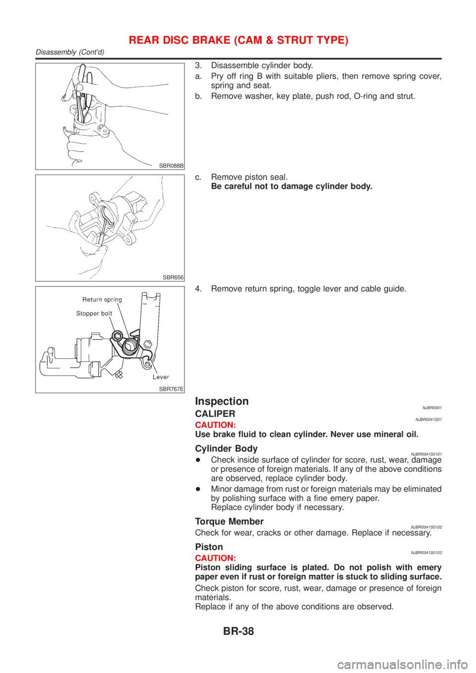
SBR088B
3. Disassemble cylinder body.
a. Pry off ring B with suitable pliers, then remove spring cover,
spring and seat.
b. Remove washer, key plate, push rod, O-ring and strut.
SBR656
c. Remove piston seal.
Be careful not to damage cylinder body.
SBR767E
4. Remove return spring, toggle lever and cable guide.
InspectionNJBR0041CALIPERNJBR0041S01CAUTION:
Use brake fluid to clean cylinder. Never use mineral oil.
Cylinder BodyNJBR0041S0101+Check inside surface of cylinder for score, rust, wear, damage
or presence of foreign materials. If any of the above conditions
are observed, replace cylinder body.
+Minor damage from rust or foreign materials may be eliminated
by polishing surface with a fine emery paper.
Replace cylinder body if necessary.
Torque MemberNJBR0041S0102Check for wear, cracks or other damage. Replace if necessary.
PistonNJBR0041S0103CAUTION:
Piston sliding surface is plated. Do not polish with emery
paper even if rust or foreign matter is stuck to sliding surface.
Check piston for score, rust, wear, damage or presence of foreign
materials.
Replace if any of the above conditions are observed.
REAR DISC BRAKE (CAM & STRUT TYPE)
Disassembly (Cont'd)
BR-38
Page 1797 of 2493
Checking and Adjusting Drive BeltsNJST0011Refer to EM-15, ªChecking Drive Beltsº.
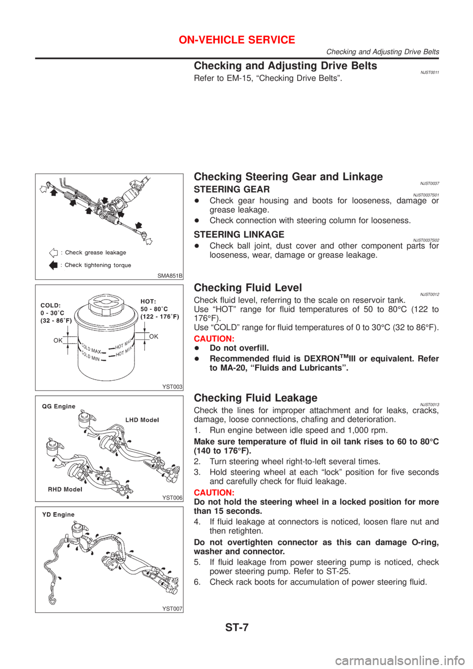
SMA851B
Checking Steering Gear and LinkageNJST0037STEERING GEARNJST0037S01+Check gear housing and boots for looseness, damage or
grease leakage.
+Check connection with steering column for looseness.
STEERING LINKAGENJST0037S02+Check ball joint, dust cover and other component parts for
looseness, wear, damage or grease leakage.
YST003
Checking Fluid LevelNJST0012Check fluid level, referring to the scale on reservoir tank.
Use ªHOTº range for fluid temperatures of 50 to 80ÉC (122 to
176ÉF).
Use ªCOLDº range for fluid temperatures of 0 to 30ÉC (32 to 86ÉF).
CAUTION:
+Do not overfill.
+Recommended fluid is DEXRON
TMIII or equivalent. Refer
to MA-20, ªFluids and Lubricantsº.
YST006
YST007
Checking Fluid LeakageNJST0013Check the lines for improper attachment and for leaks, cracks,
damage, loose connections, chafing and deterioration.
1. Run engine between idle speed and 1,000 rpm.
Make sure temperature of fluid in oil tank rises to 60 to 80ÉC
(140 to 176ÉF).
2. Turn steering wheel right-to-left several times.
3. Hold steering wheel at each ªlockº position for five seconds
and carefully check for fluid leakage.
CAUTION:
Do not hold the steering wheel in a locked position for more
than 15 seconds.
4. If fluid leakage at connectors is noticed, loosen flare nut and
then retighten.
Do not overtighten connector as this can damage O-ring,
washer and connector.
5. If fluid leakage from power steering pump is noticed, check
power steering pump. Refer to ST-25.
6. Check rack boots for accumulation of power steering fluid.
ON-VEHICLE SERVICE
Checking and Adjusting Drive Belts
ST-7
Page 2071 of 2493
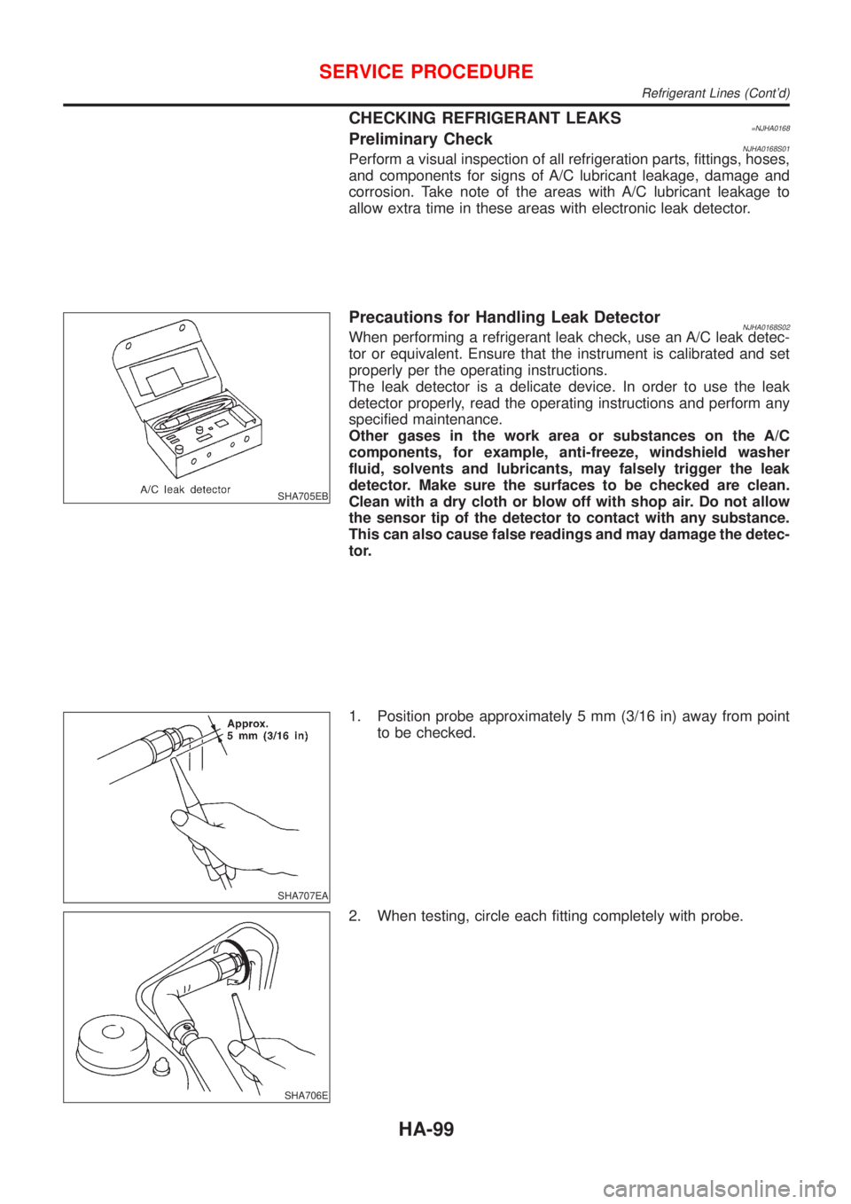
CHECKING REFRIGERANT LEAKS=NJHA0168Preliminary CheckNJHA0168S01Perform a visual inspection of all refrigeration parts, fittings, hoses,
and components for signs of A/C lubricant leakage, damage and
corrosion. Take note of the areas with A/C lubricant leakage to
allow extra time in these areas with electronic leak detector.
SHA705EB
Precautions for Handling Leak DetectorNJHA0168S02When performing a refrigerant leak check, use an A/C leak detec-
tor or equivalent. Ensure that the instrument is calibrated and set
properly per the operating instructions.
The leak detector is a delicate device. In order to use the leak
detector properly, read the operating instructions and perform any
specified maintenance.
Other gases in the work area or substances on the A/C
components, for example, anti-freeze, windshield washer
fluid, solvents and lubricants, may falsely trigger the leak
detector. Make sure the surfaces to be checked are clean.
Clean with a dry cloth or blow off with shop air. Do not allow
the sensor tip of the detector to contact with any substance.
This can also cause false readings and may damage the detec-
tor.
SHA707EA
1. Position probe approximately 5 mm (3/16 in) away from point
to be checked.
SHA706E
2. When testing, circle each fitting completely with probe.
SERVICE PROCEDURE
Refrigerant Lines (Cont'd)
HA-99
Page 2239 of 2493
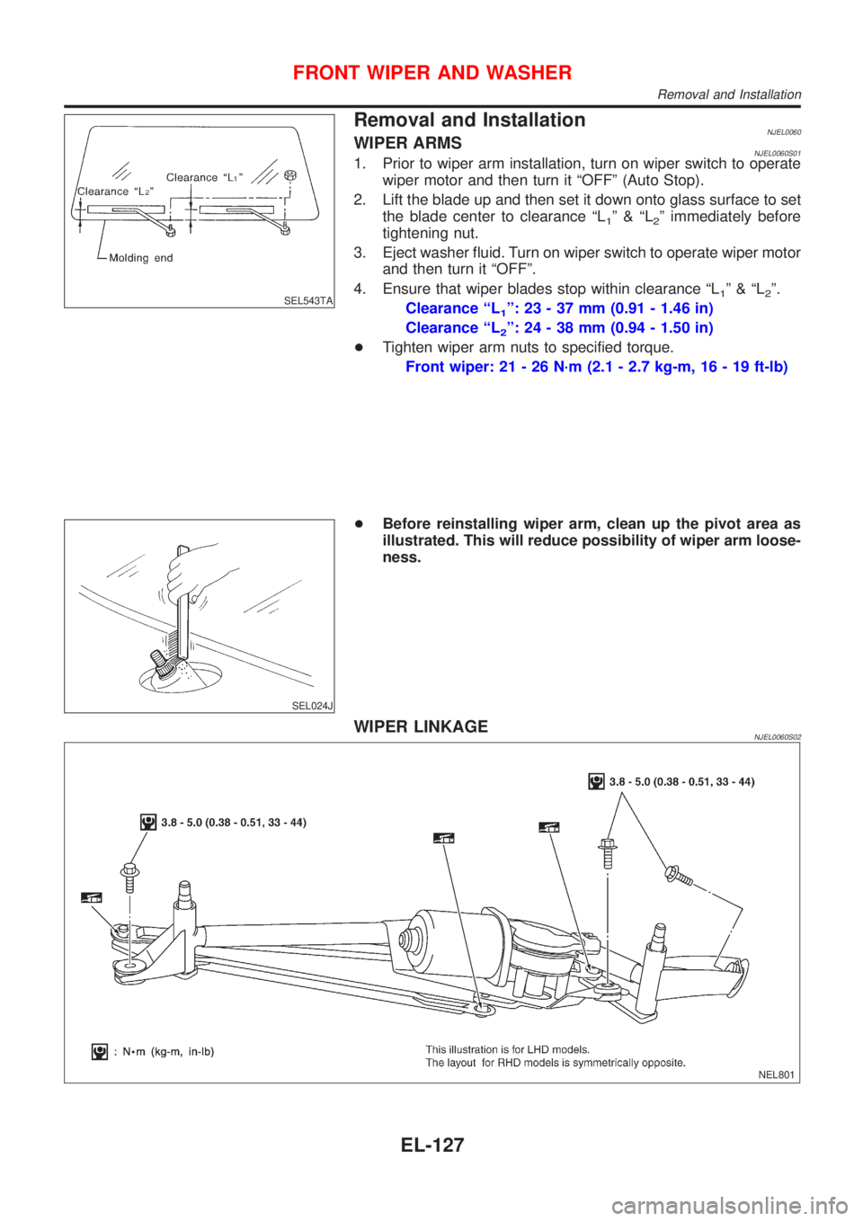
SEL543TA
Removal and InstallationNJEL0060WIPER ARMSNJEL0060S011. Prior to wiper arm installation, turn on wiper switch to operate
wiper motor and then turn it ªOFFº (Auto Stop).
2. Lift the blade up and then set it down onto glass surface to set
the blade center to clearance ªL
1º&ªL2º immediately before
tightening nut.
3. Eject washer fluid. Turn on wiper switch to operate wiper motor
and then turn it ªOFFº.
4. Ensure that wiper blades stop within clearance ªL
1º&ªL2º.
Clearance ªL
1º: 23 - 37 mm (0.91 - 1.46 in)
Clearance ªL
2º: 24 - 38 mm (0.94 - 1.50 in)
+Tighten wiper arm nuts to specified torque.
Front wiper: 21 - 26 N´m (2.1 - 2.7 kg-m, 16 - 19 ft-lb)
SEL024J
+Before reinstalling wiper arm, clean up the pivot area as
illustrated. This will reduce possibility of wiper arm loose-
ness.
WIPER LINKAGENJEL0060S02
NEL801
FRONT WIPER AND WASHER
Removal and Installation
EL-127
Page 2243 of 2493
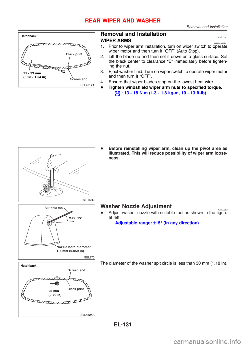
SEL451XA
Removal and InstallationNJEL0301WIPER ARMSNJEL0301S011. Prior to wiper arm installation, turn on wiper switch to operate
wiper motor and then turn it ªOFFº (Auto Stop).
2. Lift the blade up and then set it down onto glass surface. Set
the black center to clearance ªEº immediately before tighten-
ing the nut.
3. Eject washer fluid. Turn on wiper switch to operate wiper motor
and then turn it ªOFFº.
4. Ensure that wiper blades stop on the lowest heat wire.
+Tighten windshield wiper arm nuts to specified torque.
: 13 - 18 N´m (1.3 - 1.8 kg-m, 10 - 13 ft-lb)
SEL024J
+Before reinstalling wiper arm, clean up the pivot area as
illustrated. This will reduce possibility of wiper arm loose-
ness.
GEL270
Washer Nozzle AdjustmentNJEL0302+Adjust washer nozzle with suitable tool as shown in the figure
at left.
Adjustable range:±15É (In any direction)
SEL452XA
The diameter of the washer spit circle is less than 30 mm (1.18 in).
REAR WIPER AND WASHER
Removal and Installation
EL-131
Page 2479 of 2493
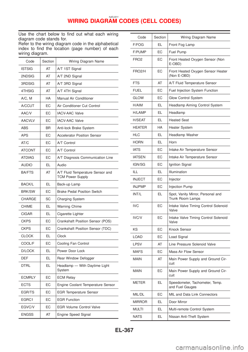
NJEL0311
Use the chart below to find out what each wiring
diagram code stands for.
Refer to the wiring diagram code in the alphabetical
index to find the location (page number) of each
wiring diagram.
Code Section Wiring Diagram Name
ISTSIG AT A/T 1ST Signal
2NDSIG AT A/T 2ND Signal
3RDSIG AT A/T 3RD Signal
4THSIG AT A/T 4TH Signal
A/C, M HA Manual Air Conditioner
A/CCUT EC Air Conditioner Cut Control
AAC/V EC IACV-AAC Valve
AACVLV EC IACV-AAC Valve
ABS BR Anti-lock Brake System
APS EC Accelerator Position Sensor
AT/C EC A/T Control
ATCONT EC A/T Control
ATDIAG EC A/T Diagnosis Communication Line
AUDIO EL Audio
BA/FTS AT A/T Fluid Temperature Sensor and
TCM Power Supply
BACK/L EL Back-up Lamp
BRK/SW EC Brake Pedal Position Switch
CHARGE SC Charging System
CHIME EL Warning Chime
CIGAR EL Cigarette Lighter
CKPS EC Crankshaft Position Sensor (POS)
CKPS EC Crankshaft Position Sensor (TDC)
CLOCK EL Clock
COOL/F EC Cooling Fan Control
D/LOCK EL Power Door Lock
DEF EL Rear Window Defogger
DTRL EL Headlamp Ð With Daytime Light
System
ECMRLY EC ECM Relay
ECTS EC Engine Coolant Temperature Sensor
EGR/TS EC EGR Temperature Sensor
EGRC1 EC EGR Function
EGVC/V EC EGR Volume Control Valve
ENGSS AT Engine Speed Signal
Code Section Wiring Diagram Name
F/FOG EL Front Fog Lamp
F/PUMP EC Fuel Pump
FRO2 EC Front Heated Oxygen Sensor (Non
E-OBD)
FRO2/H EC Front Heated Oxygen Sensor Heater
(Non E-OBD)
FTS AT A/T Fluid Temperature Sensor
FUEL EC Fuel Injection System Function
GLOW EC Glow Control System
H/AIM EL Headlamp Aiming Control System
H/LAMP EL Headlamp
H/SEAT EL Heated Seat
HEATER HA Heater System
HLC EL Headlamp Washer
HORN EL Horn
IATS EC Intake Air Temperature Sensor
IATSEN EC Intake Air Temperature Sensor
IGN/SG EC Ignition Signal
ILL EL Illumination
INJECT EC Injector
INJPMP EC Injection Pump
INT/L EL Spot, Vanity Mirror, Personal and
Trunk Room Lamps
IVC EC Intake Valve Timing Control Solenoid
Valve
IVC/V EC Intake Valve Timing Control Solenoid
Valve
KS EC Knock Sensor
LOAD EC Load Signal
LPSV AT Line Pressure Solenoid Valve
MAFS EC Mass Air Flow Sensor
MAIN AT Main Power Supply and Ground Cir-
cuit
MAIN EC Main Power Supply and Ground Cir-
cuit
METER EL Speedometer, Tachometer, Temp.
and Fuel Gauges
MIL/DL EC MIL and Data Link Connectors
MIRROR EL Door Mirror
MULTI EL Multi-remote Control System
NATS EL Nissan Anti-Theft System
WIRING DIAGRAM CODES (CELL CODES)
EL-367