2001 NISSAN ALMERA N16 transmission fluid
[x] Cancel search: transmission fluidPage 1201 of 2493
SMA827CA
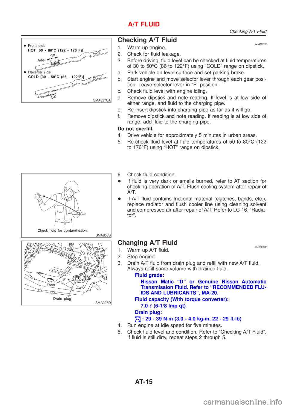
Checking A/T FluidNJAT02281. Warm up engine.
2. Check for fluid leakage.
3. Before driving, fluid level can be checked at fluid temperatures
of 30 to 50ÉC (86 to 122ÉF) using ªCOLDº range on dipstick.
a. Park vehicle on level surface and set parking brake.
b. Start engine and move selector lever through each gear posi-
tion. Leave selector lever in ªPº position.
c. Check fluid level with engine idling.
d. Remove dipstick and note reading. If level is at low side of
either range, and fluid to the charging pipe.
e. Re-insert dipstick into charging pipe as far as it will go.
f. Remove dipstick and note reading. If reading is at low side of
range, add fluid to the charging pipe.
Do not overfill.
4. Drive vehicle for approximately 5 minutes in urban areas.
5. Re-check fluid level at fluid temperatures of 50 to 80ÉC (122
to 176ÉF) using ªHOTº range on dipstick.
SMA853B
6. Check fluid condition.
+If fluid is very dark or smells burned, refer to AT section for
checking operation of A/T. Flush cooling system after repair of
A/T.
+If A/T fluid contains frictional material (clutches, bands, etc.),
replace radiator and flush cooler line using cleaning solvent
and compressed air after repair of A/T. Refer to LC-16, ªRadia-
torº.
SMA027D
Changing A/T FluidNJAT02291. Warm up A/T fluid.
2. Stop engine.
3. Drain A/T fluid from drain plug and refill with new A/T fluid.
Always refill same volume with drained fluid.
Fluid grade:
Nissan Matic ªDº or Genuine Nissan Automatic
Transmission Fluid. Refer to ªRECOMMENDED FLU-
IDS AND LUBRICANTSº, MA-20.
Fluid capacity (With torque converter):
7.0!(6-1/8 Imp qt)
Drain plug:
: 29 - 39 N´m (3.0 - 4.0 kg-m, 22 - 29 ft-lb)
4. Run engine at idle speed for five minutes.
5. Check fluid level and condition. Refer to ªChecking A/T Fluidº.
If fluid is still dirty, repeat steps 2 through 5.
A/T FLUID
Checking A/T Fluid
AT-15
Page 1216 of 2493
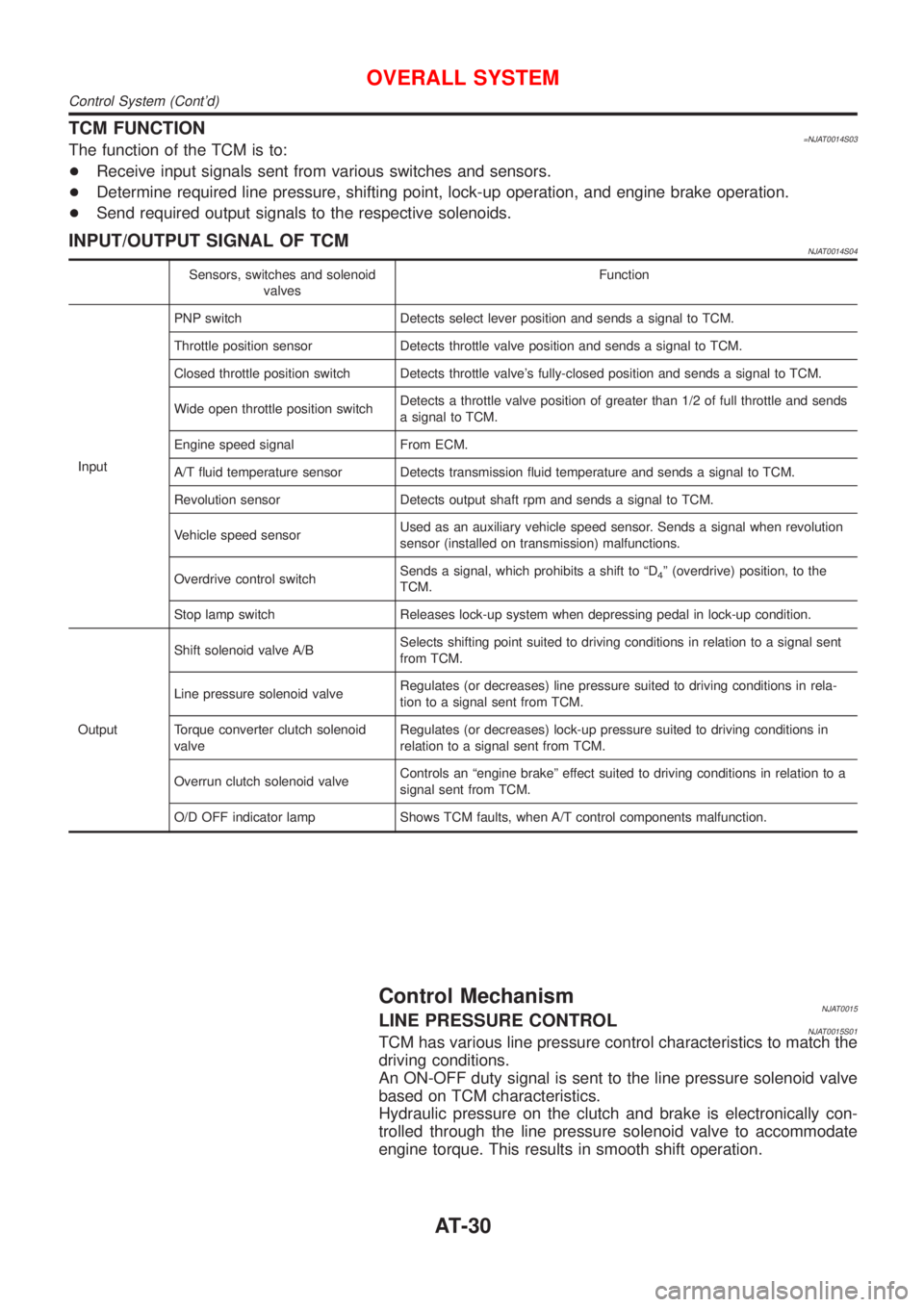
TCM FUNCTION=NJAT0014S03The function of the TCM is to:
+Receive input signals sent from various switches and sensors.
+Determine required line pressure, shifting point, lock-up operation, and engine brake operation.
+Send required output signals to the respective solenoids.
INPUT/OUTPUT SIGNAL OF TCMNJAT0014S04
Sensors, switches and solenoid
valvesFunction
InputPNP switch Detects select lever position and sends a signal to TCM.
Throttle position sensor Detects throttle valve position and sends a signal to TCM.
Closed throttle position switch Detects throttle valve's fully-closed position and sends a signal to TCM.
Wide open throttle position switchDetects a throttle valve position of greater than 1/2 of full throttle and sends
a signal to TCM.
Engine speed signal From ECM.
A/T fluid temperature sensor Detects transmission fluid temperature and sends a signal to TCM.
Revolution sensor Detects output shaft rpm and sends a signal to TCM.
Vehicle speed sensorUsed as an auxiliary vehicle speed sensor. Sends a signal when revolution
sensor (installed on transmission) malfunctions.
Overdrive control switchSends a signal, which prohibits a shift to ªD
4º (overdrive) position, to the
TCM.
Stop lamp switch Releases lock-up system when depressing pedal in lock-up condition.
OutputShift solenoid valve A/BSelects shifting point suited to driving conditions in relation to a signal sent
from TCM.
Line pressure solenoid valveRegulates (or decreases) line pressure suited to driving conditions in rela-
tion to a signal sent from TCM.
Torque converter clutch solenoid
valveRegulates (or decreases) lock-up pressure suited to driving conditions in
relation to a signal sent from TCM.
Overrun clutch solenoid valveControls an ªengine brakeº effect suited to driving conditions in relation to a
signal sent from TCM.
O/D OFF indicator lamp Shows TCM faults, when A/T control components malfunction.
Control MechanismNJAT0015LINE PRESSURE CONTROLNJAT0015S01TCM has various line pressure control characteristics to match the
driving conditions.
An ON-OFF duty signal is sent to the line pressure solenoid valve
based on TCM characteristics.
Hydraulic pressure on the clutch and brake is electronically con-
trolled through the line pressure solenoid valve to accommodate
engine torque. This results in smooth shift operation.
OVERALL SYSTEM
Control System (Cont'd)
AT-30
Page 1217 of 2493
SAT003J
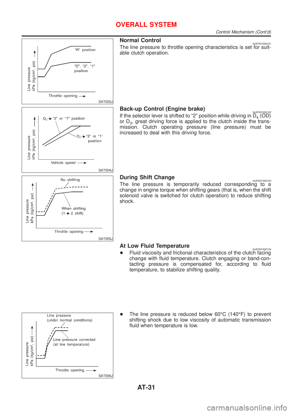
Normal ControlNJAT0015S0101The line pressure to throttle opening characteristics is set for suit-
able clutch operation.
SAT004J
Back-up Control (Engine brake)NJAT0015S0102If the selector lever is shifted to ª2º position while driving in D4(OD)
or D
3, great driving force is applied to the clutch inside the trans-
mission. Clutch operating pressure (line pressure) must be
increased to deal with this driving force.
SAT005J
During Shift ChangeNJAT0015S0103The line pressure is temporarily reduced corresponding to a
change in engine torque when shifting gears (that is, when the shift
solenoid valve is switched for clutch operation) to reduce shifting
shock.
At Low Fluid TemperatureNJAT0015S0104+Fluid viscosity and frictional characteristics of the clutch facing
change with fluid temperature. Clutch engaging or band-con-
tacting pressure is compensated for, according to fluid
temperature, to stabilize shifting quality.
SAT006J
+The line pressure is reduced below 60ÉC (140ÉF) to prevent
shifting shock due to low viscosity of automatic transmission
fluid when temperature is low.
OVERALL SYSTEM
Control Mechanism (Cont'd)
AT-31
Page 1219 of 2493
Pilot pressure generated by the operation of shift solenoid valves
A and B is applied to the end face of shift valves A and B.
The drawing above shows the operation of shift valve B. When the
shift solenoid valve is ªONº, pilot pressure applied to the end face
of the shift valve overcomes spring force, moving the valve upward.
LOCK-UP CONTROLNJAT0015S03The torque converter clutch piston in the torque converter is locked
to eliminate torque converter slip to increase power transmission
efficiency. The solenoid valve is controlled by an ON-OFF duty
signal sent from the TCM. The signal is converted to an oil pres-
sure signal which controls the torque converter clutch piston.
Conditions for Lock-up OperationNJAT0015S0301When vehicle is driven in 4th gear position, vehicle speed and
throttle opening are detected. If the detected values fall within the
lock-up zone memorized in the TCM, lock-up is performed.
Overdrive control switch ON OFF
Selector lever ªDº position
Gear position D
4D3
Vehicle speed sensor More than set value
Throttle position sensor Less than set opening
Closed throttle position switch OFF
A/T fluid temperature sensor More than 40ÉC (104ÉF)
SAT010J
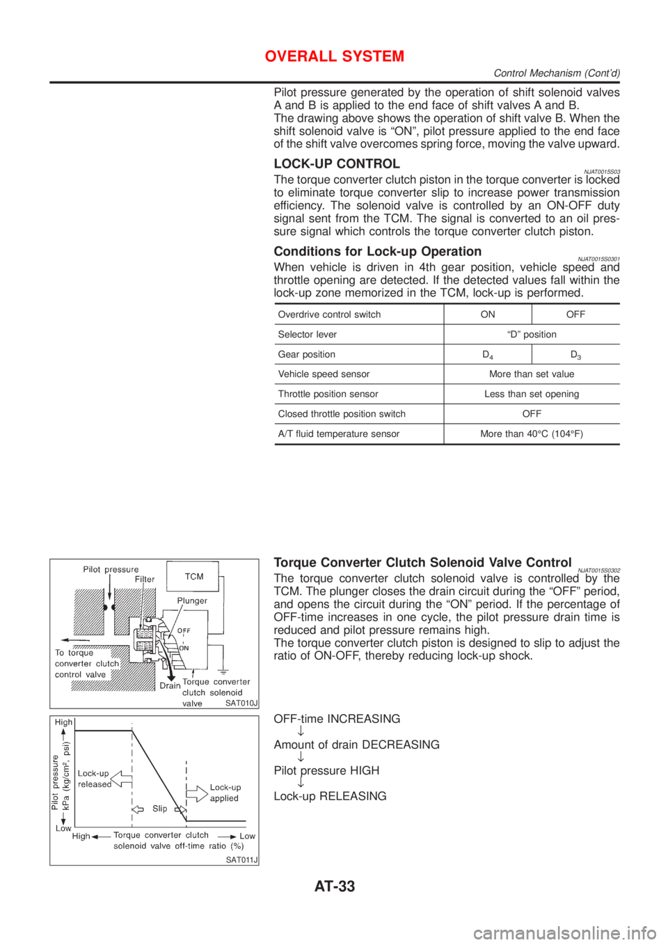
Torque Converter Clutch Solenoid Valve ControlNJAT0015S0302The torque converter clutch solenoid valve is controlled by the
TCM. The plunger closes the drain circuit during the ªOFFº period,
and opens the circuit during the ªONº period. If the percentage of
OFF-time increases in one cycle, the pilot pressure drain time is
reduced and pilot pressure remains high.
The torque converter clutch piston is designed to slip to adjust the
ratio of ON-OFF, thereby reducing lock-up shock.
SAT011J
OFF-time INCREASING
¯
Amount of drain DECREASING
¯
Pilot pressure HIGH
¯
Lock-up RELEASING
OVERALL SYSTEM
Control Mechanism (Cont'd)
AT-33
Page 1264 of 2493
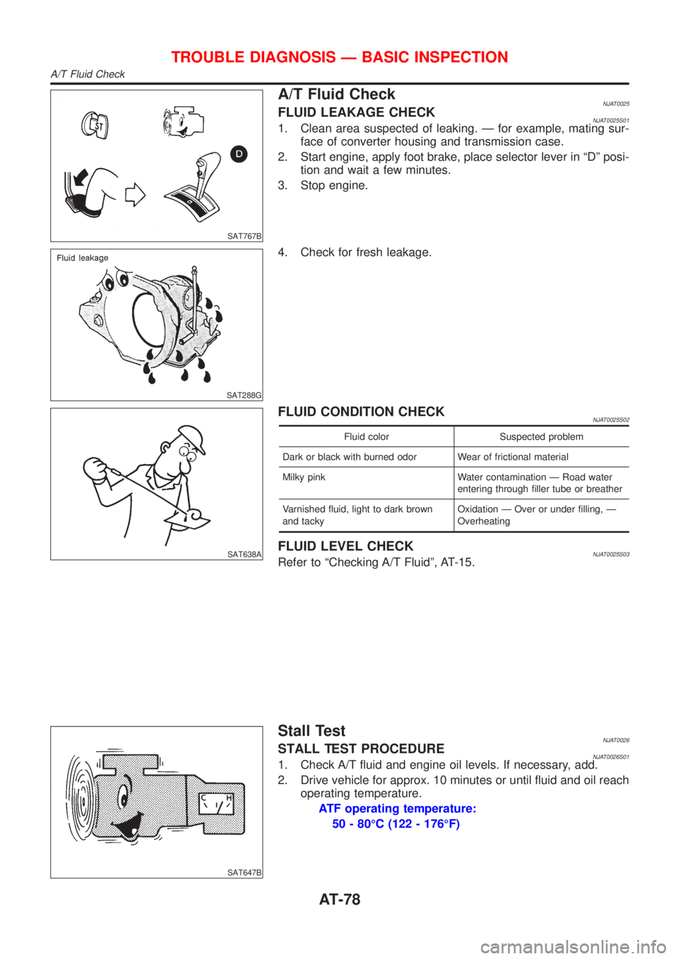
SAT767B
A/T Fluid CheckNJAT0025FLUID LEAKAGE CHECKNJAT0025S011. Clean area suspected of leaking. Ð for example, mating sur-
face of converter housing and transmission case.
2. Start engine, apply foot brake, place selector lever in ªDº posi-
tion and wait a few minutes.
3. Stop engine.
SAT288G
4. Check for fresh leakage.
SAT638A
FLUID CONDITION CHECKNJAT0025S02
Fluid color Suspected problem
Dark or black with burned odor Wear of frictional material
Milky pink Water contamination Ð Road water
entering through filler tube or breather
Varnished fluid, light to dark brown
and tackyOxidation Ð Over or under filling, Ð
Overheating
FLUID LEVEL CHECKNJAT0025S03Refer to ªChecking A/T Fluidº, AT-15.
SAT647B
Stall TestNJAT0026STALL TEST PROCEDURENJAT0026S011. Check A/T fluid and engine oil levels. If necessary, add.
2. Drive vehicle for approx. 10 minutes or until fluid and oil reach
operating temperature.
ATF operating temperature:
50 - 80ÉC (122 - 176ÉF)
TROUBLE DIAGNOSIS Ð BASIC INSPECTION
A/T Fluid Check
AT-78
Page 1298 of 2493
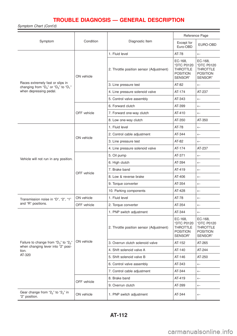
Symptom Condition Diagnostic ItemReference Page
Except for
Euro-OBDEURO-OBD
Races extremely fast or slips in
changing from ªD
4ºorªD3ºtoªD1º
when depressing pedal.ON vehicle1. Fluid level AT-78¬
2. Throttle position sensor (Adjustment)EC-168,
ªDTC P0120
THROTTLE
POSITION
SENSORºEC-168,
ªDTC P0120
THROTTLE
POSITION
SENSORº
3. Line pressure test AT-82¬
4. Line pressure solenoid valve AT-174 AT-237
5. Control valve assembly AT-343¬
OFF vehicle6. Forward clutch AT-399¬
7. Forward one-way clutch AT-410¬
8. Low one-way clutch AT-350 AT-350
Vehicle will not run in any position.ON vehicle1. Fluid level AT-78¬
2. Control cable adjustment AT-344¬
3. Line pressure test AT-82¬
4. Line pressure solenoid valve AT-174 AT-237
OFF vehicle5. Oil pump AT-371¬
6. High clutch AT-394¬
7. Brake band AT-419¬
8. Low & reverse brake AT-406¬
9. Torque converter AT-354¬
10. Parking components AT-428¬
Transmission noise in ªDº, ª2º, ª1º
and ªRº positions.ON vehicle 1. Fluid level AT-78¬
OFF vehicle 2. Torque converter AT-354¬
Failure to change from ªD
3ºtoª22º
when changing lever into ª2º posi-
tion.
AT-320ON vehicle1. PNP switch adjustment AT-344¬
2. Throttle position sensor (Adjustment)EC-168,
ªDTC P0120
THROTTLE
POSITION
SENSORºEC-168,
ªDTC P0120
THROTTLE
POSITION
SENSORº
3. Overrun clutch solenoid valve AT-152 AT-265
4. Shift solenoid valve A AT-140 AT-244
5. Shift solenoid valve B AT-146 AT-250
6. Control valve assembly AT-343¬
7. Control cable adjustment AT-344¬
OFF vehicle8. Brake band AT-419¬
9. Overrun clutch AT-399¬
Gear change from ª2
2ºtoª23ºin
ª2º position.ON vehicle 1. PNP switch adjustment AT-344¬
TROUBLE DIAGNOSIS Ð GENERAL DESCRIPTION
Symptom Chart (Cont'd)
AT-112
Page 1300 of 2493
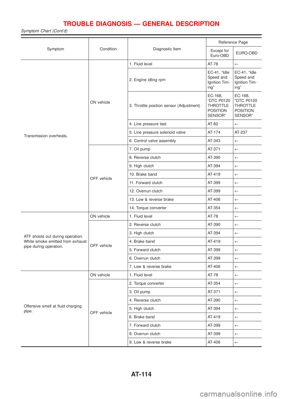
Symptom Condition Diagnostic ItemReference Page
Except for
Euro-OBDEURO-OBD
Transmission overheats.ON vehicle1. Fluid level AT-78¬
2. Engine idling rpmEC-41, ªIdle
Speed and
Ignition Tim-
ingºEC-41, ªIdle
Speed and
Ignition Tim-
ingº
3. Throttle position sensor (Adjustment)EC-168,
ªDTC P0120
THROTTLE
POSITION
SENSORºEC-168,
ªDTC P0120
THROTTLE
POSITION
SENSORº
4. Line pressure test AT-82¬
5. Line pressure solenoid valve AT-174 AT-237
6. Control valve assembly AT-343¬
OFF vehicle7. Oil pump AT-371¬
8. Reverse clutch AT-390¬
9. High clutch AT-394¬
10. Brake band AT-419¬
11. Forward clutch AT-399¬
12. Overrun clutch AT-399¬
13. Low & reverse brake AT-406¬
14. Torque converter AT-354¬
ATF shoots out during operation.
White smoke emitted from exhaust
pipe during operation.ON vehicle 1. Fluid level AT-78¬
OFF vehicle2. Reverse clutch AT-390¬
3. High clutch AT-394¬
4. Brake band AT-419¬
5. Forward clutch AT-399¬
6. Overrun clutch AT-399¬
7. Low & reverse brake AT-406¬
Offensive smell at fluid charging
pipe.ON vehicle 1. Fluid level AT-78¬
OFF vehicle2. Torque converter AT-354¬
3. Oil pump AT-371¬
4. Reverse clutch AT-390¬
5. High clutch AT-394¬
6. Brake band AT-419¬
7. Forward clutch AT-399¬
8. Overrun clutch AT-399¬
9. Low & reverse brake AT-406¬
TROUBLE DIAGNOSIS Ð GENERAL DESCRIPTION
Symptom Chart (Cont'd)
AT-114
Page 1396 of 2493
SAT014K
SAT971J
SAT021J
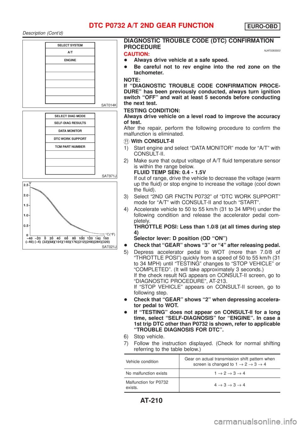
DIAGNOSTIC TROUBLE CODE (DTC) CONFIRMATION
PROCEDURE
NJAT0283S03CAUTION:
+Always drive vehicle at a safe speed.
+Be careful not to rev engine into the red zone on the
tachometer.
NOTE:
If ªDIAGNOSTIC TROUBLE CODE CONFIRMATION PROCE-
DUREº has been previously conducted, always turn ignition
switch ªOFFº and wait at least 5 seconds before conducting
the next test.
TESTING CONDITION:
Always drive vehicle on a level road to improve the accuracy
of test.
After the repair, perform the following procedure to confirm the
malfunction is eliminated.
With CONSULT-II
1) Start engine and select ªDATA MONITORº mode for ªA/Tº with
CONSULT-II.
2) Make sure that output voltage of A/T fluid temperature sensor
is within the range below.
FLUID TEMP SEN: 0.4 - 1.5V
If out of range, drive the vehicle to decrease the voltage (warm
up the fluid) or stop engine to increase the voltage (cool down
the fluid).
3) Select ª2ND GR FNCTN P0732º of ªDTC WORK SUPPORTº
mode for ªA/Tº with CONSULT-II and touch ªSTARTº.
4) Accelerate vehicle to 50 to 55 km/h (31 to 34 MPH) under the
following condition and release the accelerator pedal com-
pletely.
THROTTLE POSI: Less than 1.0/8 (at all times during step
4)
Selector lever: D position (OD ªONº)
+Check that ªGEARº shows ª3º or ª4º after releasing pedal.
5) Depress accelerator pedal to WOT (more than 7.0/8 of
ªTHROTTLE POSIº) quickly from a speed of 50 to 55 km/h (31
to 34 MPH) until ªTESTINGº changes to ªSTOP VEHICLEº or
ªCOMPLETEDº. (It will take approximately 3 seconds.)
If the check result NG appears on CONSULT-II screen, go to
ªDIAGNOSTIC PROCEDUREº, AT-213.
If ªSTOP VEHICLEº appears on CONSULT-II screen, go to
following step.
+Check that ªGEARº shows ª2º when depressing accelera-
tor pedal to WOT.
+If ªTESTINGº does not appear on CONSULT-II for a long
time, select ªSELF-DIAGNOSISº for ªENGINEº. In case a
1st trip DTC other than P0732 is shown, refer to applicable
ªTROUBLE DIAGNOSIS FOR DTCº.
6) Stop vehicle.
7) Follow the instruction displayed. (Check for normal shifting
referring to the table below.)
Vehicle conditionGear on actual transmission shift pattern when
screen is changed to 1®2®3®4
No malfunction exists 1®2®3®4
Malfunction for P0732
exists.4®3®3®4
DTC P0732 A/T 2ND GEAR FUNCTIONEURO-OBD
Description (Cont'd)
AT-210