Page 1402 of 2493

SAT014K
SAT971J
SAT021J
DIAGNOSTIC TROUBLE CODE (DTC) CONFIRMATION
PROCEDURE
NJAT0287S03CAUTION:
+Always drive vehicle at a safe speed.
+Be careful not to rev engine into the red zone on the
tachometer.
NOTE:
If ªDIAGNOSTIC TROUBLE CODE CONFIRMATION PROCE-
DUREº has been previously conducted, always turn ignition
switch ªOFFº and wait at least 5 seconds before conducting
the next test.
TESTING CONDITION:
Always drive vehicle on a level road to improve the accuracy
of test.
After the repair, perform the following procedure to confirm the
malfunction is eliminated.
With CONSULT-II
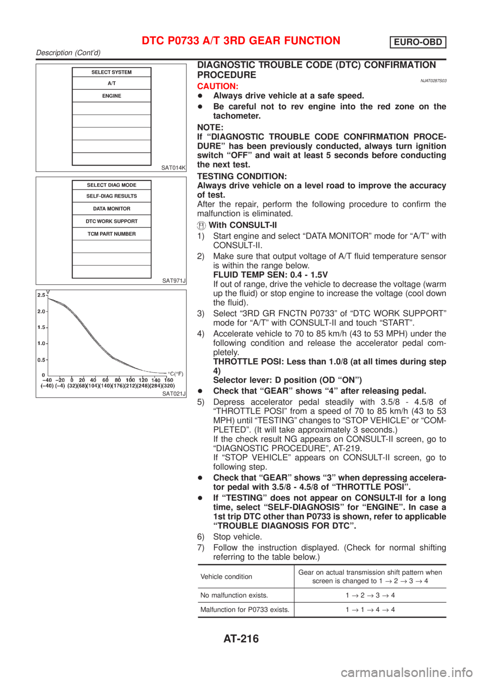
1) Start engine and select ªDATA MONITORº mode for ªA/Tº with
CONSULT-II.
2) Make sure that output voltage of A/T fluid temperature sensor
is within the range below.
FLUID TEMP SEN: 0.4 - 1.5V
If out of range, drive the vehicle to decrease the voltage (warm
up the fluid) or stop engine to increase the voltage (cool down
the fluid).
3) Select ª3RD GR FNCTN P0733º of ªDTC WORK SUPPORTº
mode for ªA/Tº with CONSULT-II and touch ªSTARTº.
4) Accelerate vehicle to 70 to 85 km/h (43 to 53 MPH) under the
following condition and release the accelerator pedal com-
pletely.
THROTTLE POSI: Less than 1.0/8 (at all times during step
4)
Selector lever: D position (OD ªONº)
+Check that ªGEARº shows ª4º after releasing pedal.
5) Depress accelerator pedal steadily with 3.5/8 - 4.5/8 of
ªTHROTTLE POSIº from a speed of 70 to 85 km/h (43 to 53
MPH) until ªTESTINGº changes to ªSTOP VEHICLEº or ªCOM-
PLETEDº. (It will take approximately 3 seconds.)
If the check result NG appears on CONSULT-II screen, go to
ªDIAGNOSTIC PROCEDUREº, AT-219.
If ªSTOP VEHICLEº appears on CONSULT-II screen, go to
following step.
+Check that ªGEARº shows ª3º when depressing accelera-
tor pedal with 3.5/8 - 4.5/8 of ªTHROTTLE POSIº.
+If ªTESTINGº does not appear on CONSULT-II for a long
time, select ªSELF-DIAGNOSISº for ªENGINEº. In case a
1st trip DTC other than P0733 is shown, refer to applicable
ªTROUBLE DIAGNOSIS FOR DTCº.
6) Stop vehicle.
7) Follow the instruction displayed. (Check for normal shifting
referring to the table below.)
Vehicle conditionGear on actual transmission shift pattern when
screen is changed to 1®2®3®4
No malfunction exists. 1®2®3®4
Malfunction for P0733 exists. 1®1®4®4
DTC P0733 A/T 3RD GEAR FUNCTIONEURO-OBD
Description (Cont'd)
AT-216
Page 1592 of 2493
Low & Reverse Brake
COMPONENTS=NJAT0153
SAT039K
SAT230D
DISASSEMBLYNJAT01541. Check operation of low & reverse brake.
a. Apply compressed air to oil hole of transmission case.
b. Check to see that retaining plate moves to snap ring.
c. If retaining plate does not contact snap ring:
+D-ring might be damaged.
+Oil seal might be damaged.
+Fluid might be leaking past piston check ball.
SAT231D
2. Stand transmission case.
3. Remove snap ring.
4. Remove drive plates, driven plates, retaining plate from trans-
mission case.
REPAIR FOR COMPONENT PARTS
Low & Reverse Brake
AT-406
Page 1634 of 2493
SAT426DB
d. Usea4mm(0.157 in) pin for this adjustment.
1) Insert the pin straight into the manual shaft adjustment hole.
2) Rotate PNP switch until the pin can also be inserted straight
into hole in PNP switch.
e. Tighten PNP switch fixing bolts.
f. Remove pin from adjustment hole after adjusting PNP switch.
SAT586H
10. Install oil charging pipe and oil cooler tube to transmission
case.
SAT428DA
11. Install torque converter.
a. Pour ATF into torque converter.
+Approximately 1 liter (7/8 Imp qt) of fluid is required for a
new torque converter.
+When reusing old torque converter, add the same amount
of fluid as was drained.
SAT429D
b. Install torque converter while aligning notches of torque con-
verter with notches of oil pump.
SAT430D
c. Measure distance ªAº to check that torque converter is in
proper position.
Distance ªAº:
15.9 mm (0.626 in) or more
ASSEMBLY
Assembly (4) (Cont'd)
AT-448
Page 1693 of 2493

SRA695A
SSU038
REMOVALNJSU0031S01CAUTION:
+Before removing the rear suspension assembly, discon-
nect the ABS wheel sensor from the assembly. Failure to
do so may result in damage to the sensor wires and the
sensor becoming inoperative.
+Remove suspension assembly.
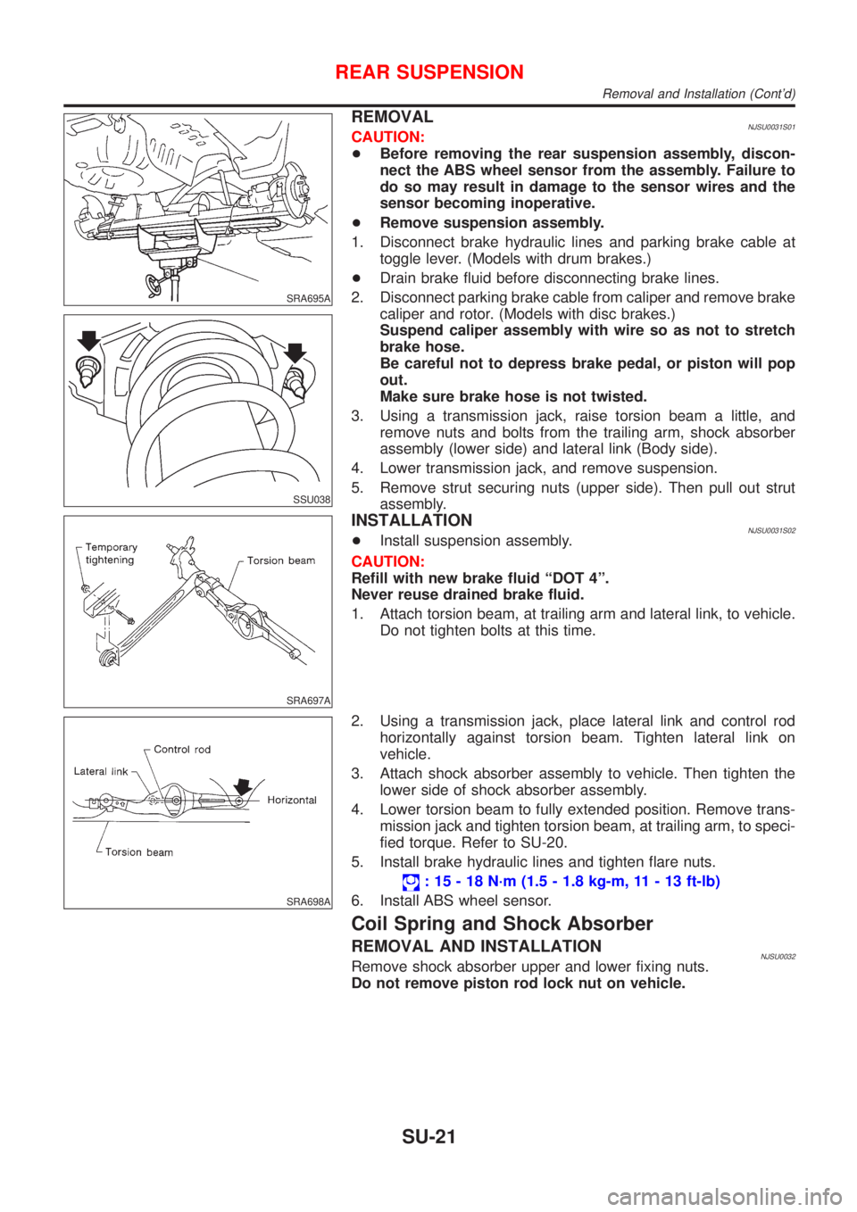
1. Disconnect brake hydraulic lines and parking brake cable at
toggle lever. (Models with drum brakes.)
+Drain brake fluid before disconnecting brake lines.
2. Disconnect parking brake cable from caliper and remove brake
caliper and rotor. (Models with disc brakes.)
Suspend caliper assembly with wire so as not to stretch
brake hose.
Be careful not to depress brake pedal, or piston will pop
out.
Make sure brake hose is not twisted.
3. Using a transmission jack, raise torsion beam a little, and
remove nuts and bolts from the trailing arm, shock absorber
assembly (lower side) and lateral link (Body side).
4. Lower transmission jack, and remove suspension.
5. Remove strut securing nuts (upper side). Then pull out strut
assembly.
SRA697A
INSTALLATIONNJSU0031S02+Install suspension assembly.
CAUTION:
Refill with new brake fluid ªDOT 4º.
Never reuse drained brake fluid.
1. Attach torsion beam, at trailing arm and lateral link, to vehicle.
Do not tighten bolts at this time.
SRA698A
2. Using a transmission jack, place lateral link and control rod
horizontally against torsion beam. Tighten lateral link on
vehicle.
3. Attach shock absorber assembly to vehicle. Then tighten the
lower side of shock absorber assembly.
4. Lower torsion beam to fully extended position. Remove trans-
mission jack and tighten torsion beam, at trailing arm, to speci-
fied torque. Refer to SU-20.
5. Install brake hydraulic lines and tighten flare nuts.
: 15 - 18 N´m (1.5 - 1.8 kg-m, 11 - 13 ft-lb)
6. Install ABS wheel sensor.
Coil Spring and Shock Absorber
REMOVAL AND INSTALLATIONNJSU0032Remove shock absorber upper and lower fixing nuts.
Do not remove piston rod lock nut on vehicle.
REAR SUSPENSION
Removal and Installation (Cont'd)
SU-21
Page:
< prev 1-8 9-16 17-24