Page 1533 of 2493

AAT259A
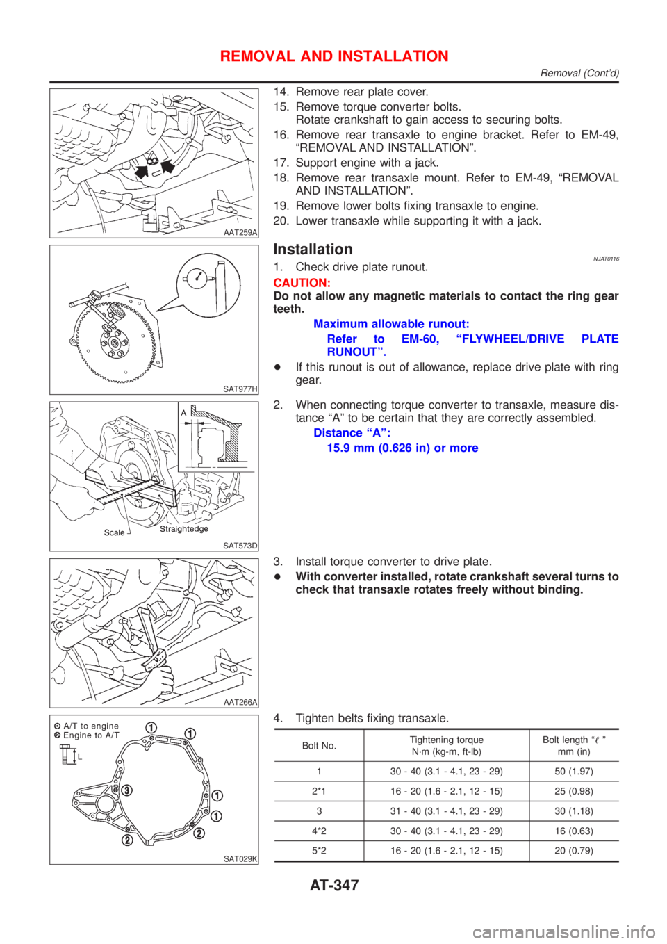
14. Remove rear plate cover.
15. Remove torque converter bolts.
Rotate crankshaft to gain access to securing bolts.
16. Remove rear transaxle to engine bracket. Refer to EM-49,
ªREMOVAL AND INSTALLATIONº.
17. Support engine with a jack.
18. Remove rear transaxle mount. Refer to EM-49, ªREMOVAL
AND INSTALLATIONº.
19. Remove lower bolts fixing transaxle to engine.
20. Lower transaxle while supporting it with a jack.
SAT977H
InstallationNJAT01161. Check drive plate runout.
CAUTION:
Do not allow any magnetic materials to contact the ring gear
teeth.
Maximum allowable runout:
Refer to EM-60, ªFLYWHEEL/DRIVE PLATE
RUNOUTº.
+If this runout is out of allowance, replace drive plate with ring
gear.
SAT573D
2. When connecting torque converter to transaxle, measure dis-
tance ªAº to be certain that they are correctly assembled.
Distance ªAº:
15.9 mm (0.626 in) or more
AAT266A
3. Install torque converter to drive plate.
+With converter installed, rotate crankshaft several turns to
check that transaxle rotates freely without binding.
SAT029K
4. Tighten belts fixing transaxle.
Bolt No.Tightening torque
N´m (kg-m, ft-lb)Bolt length ª!º
mm (in)
1 30 - 40 (3.1 - 4.1, 23 - 29) 50 (1.97)
2*1 16 - 20 (1.6 - 2.1, 12 - 15) 25 (0.98)
3 31 - 40 (3.1 - 4.1, 23 - 29) 30 (1.18)
4*2 30 - 40 (3.1 - 4.1, 23 - 29) 16 (0.63)
5*2 16 - 20 (1.6 - 2.1, 12 - 15) 20 (0.79)
REMOVAL AND INSTALLATION
Removal (Cont'd)
AT-347
Page 1540 of 2493
NJAT0120
SAT049K
1. Drain ATF through drain plug.
SAT008D
2. Remove torque converter.
SAT009D
3. Check torque converter one-way clutch using check tool as
shown at left.
a. Insert check tool into the groove of bearing support built into
one-way clutch outer race.
b. While fixing bearing support with check tool, rotate one-way
clutch spline using flat-bladed screwdriver.
c. Check inner race rotates clockwise only. If not, replace torque
converter assembly.
SAT586H
4. Remove oil charging pipe and oil cooler tube.
DISASSEMBLY
AT-354
Page 1565 of 2493
SAT115D
Oil StrainerNJAT0131S02+Check wire netting of oil strainer for damage.
SAT322GC
Shift Solenoid Valves A and B, Line Pressure Solenoid
Valve, Torque Converter Clutch Solenoid Valve and
Overrun Clutch Solenoid Valve
NJAT0131S03+Refer to ªResistance Checkº of each solenoid valve.
ValvesExcept for Euro-
OBDEuro-OBD
Shift solenoid valve A AT-145 AT-249
Shift solenoid vavle B AT-151 AT-255
Line pressure solenoid valve AT-180 AT-243
Torque converter clutch solenoid valve AT-162 AT-236
Overrun clutch solenoid valve AT-156 AT-270
SAT138D
Oil Cooler Relief Valve SpringNJAT0131S04+Check springs for damage or deformation.
+Measure free length and outer diameter.
Inspection standard:
Unit: mm (in)
Part No.!D
31872 31X00 17.0 (0.669) 8.0 (0.315)
SAT871J
ASSEMBLYNJAT01321. Install upper, inter and lower body.
a. Place oil circuit of upper body face up. Install steel balls in their
proper positions.
REPAIR FOR COMPONENT PARTS
Control Valve Assembly (Cont'd)
AT-379
Page 1568 of 2493
3. Install and tighten bolts.
Bolt length, number and location:
Bolt symbolABCDE FG
Bolt length ª!º
13.5 mm
(0.531 in)58.0 mm
(2.283 in)44.0 mm
(1.732 in)66.0 mm
(2.598 in)33.0 mm
(1.299 in)78.0 mm
(3.071 in)18.0 mm
(0.709 in)
Number of bolts 6 3 6 11 2 2 1
F: Reamer bolt with nut
SAT869J
SAT081F
a. Install and tighten boltsBto specified torque.
:7-9N´m(0.7 - 0.9 kg-m, 61 - 78 in-lb)
SAT316GA
b. Install solenoid valve assembly and line pressure solenoid
valve to lower body.
REPAIR FOR COMPONENT PARTS
Control Valve Assembly (Cont'd)
AT-382
Page 1569 of 2493
SAT323G
c. Remove reamer boltsFand set oil strainer on control valve
assembly.
d. Reinstall reamer boltsFfrom lower body side.
SAT083F
e. Tighten boltsA,C,DandFto specified torque.
:7-9N´m(0.7 - 0.9 kg-m, 61 - 78 in-lb)
SAT084FA
f. Tighten boltsEto specified torque.
: 3.4 - 4.4 N´m (0.35 - 0.45 kg-m, 30.4 - 39.1 in-lb)
REPAIR FOR COMPONENT PARTS
Control Valve Assembly (Cont'd)
AT-383
Page 1570 of 2493

Control Valve Upper Body
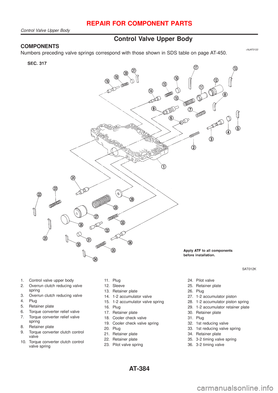
COMPONENTS=NJAT0133Numbers preceding valve springs correspond with those shown in SDS table on page AT-450.
SAT012K
1. Control valve upper body
2. Overrun clutch reducing valve
spring
3. Overrun clutch reducing valve
4. Plug
5. Retainer plate
6. Torque converter relief valve
7. Torque converter relief valve
spring
8. Retainer plate
9. Torque converter clutch control
valve
10. Torque converter clutch control
valve spring11. Plug
12. Sleeve
13. Retainer plate
14. 1-2 accumulator valve
15. 1-2 accumulator valve spring
16. Plug
17. Retainer plate
18. Cooler check valve
19. Cooler check valve spring
20. Plug
21. Retainer plate
22. Retainer plate
23. Pilot valve spring24. Pilot valve
25. Retainer plate
26. Plug
27. 1-2 accumulator piston
28. 1-2 accumulator piston spring
29. 1-2 accumulator retainer plate
30. Retainer plate
31. Plug
32. 1st reducing valve
33. 1st reducing valve spring
34. Retainer plate
35. 3-2 timing valve spring
36. 3-2 timing valve
REPAIR FOR COMPONENT PARTS
Control Valve Upper Body
AT-384
Page 1573 of 2493
SAT086F
Retainer Plate (for control valve upper body)NJAT0136S02Refer to AT-384.
Unit: mm (in)
Name of valve and piston No. Length A Length B
Pilot valve 22
6.0 (0.236)21.5 (0.846)
1-2 accumulator valve 17
40.5 (1.59)
1-2 accumulator piston 25
1st reducing valve 30 21.5 (0.846)
Overrun clutch reducing valve 5 24.0 (0.945)
Torque converter relief valve 8 21.5 (0.846)
Torque converter clutch control valve 13 28.0 (1.102)
3-2 timing valve 34 21.5 (0.846)
Cooler check valve 21 24.0 (0.945)
+Install proper retainer plates.
REPAIR FOR COMPONENT PARTS
Control Valve Upper Body (Cont'd)
AT-387
Page 1615 of 2493
SAT330D
5. Install return spring.
NAT059
Adjustment (1)NJAT0174DIFFERENTIAL SIDE BEARING PRELOADNJAT0174S011. Install differential side bearing outer race without adjusting
shim on transmission case.
2. Install differential side bearing outer race on converter housing.
SAT027D
3. Place final drive assembly on transmission case.
4. Install transmission case on converter housing. Tighten trans-
mission case fixing boltsAandBto the specified torque.
NAT060
5. Attach dial indicator on differential case at transmission case
side.
6. Insert Tool into differential side gear from converter housing.
7. Move Tool up and down and measure dial indicator deflection.
Differential side bearing preload ªTº:
0.04 - 0.09 mm (0.0016 - 0.0035 in)
8. Select proper thickness of differential side bearing adjusting
shim(s) using SDS table as a guide.
Differential side bearing adjusting shim:
Refer to SDS, AT-454.
ASSEMBLY
Assembly (1) (Cont'd)
AT-429