Page 1616 of 2493

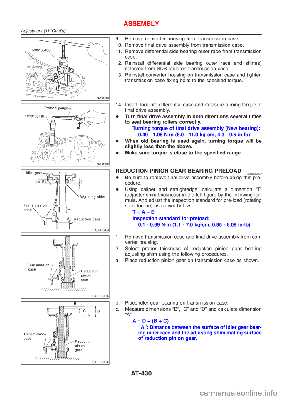
NAT033
9. Remove converter housing from transmission case.
10. Remove final drive assembly from transmission case.
11. Remove differential side bearing outer race from transmission
case.
12. Reinstall differential side bearing outer race and shim(s)
selected from SDS table on transmission case.
13. Reinstall converter housing on transmission case and tighten
transmission case fixing bolts to the specified torque.
NAT062
14. Insert Tool into differential case and measure turning torque of
final drive assembly.
+Turn final drive assembly in both directions several times
to seat bearing rollers correctly.
Turning torque of final drive assembly (New bearing):
0.49 - 1.08 N´m (5.0 - 11.0 kg-cm, 4.3 - 9.5 in-lb)
+When old bearing is used again, turning torque will be
slightly less than the above.
+Make sure torque is close to the specified range.
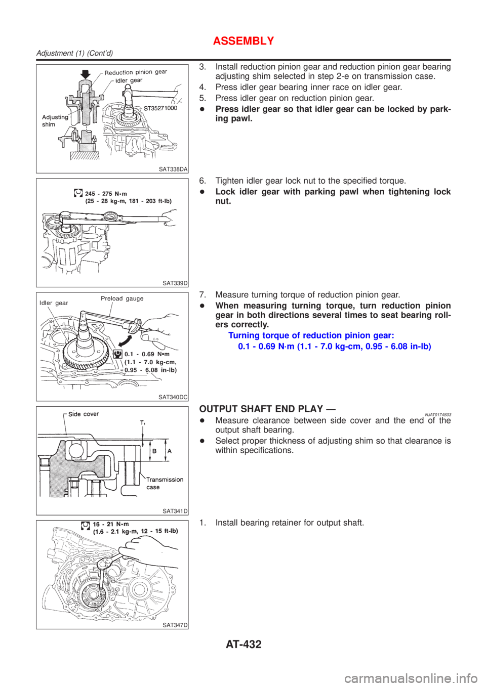
SAT876J
REDUCTION PINION GEAR BEARING PRELOADNJAT0174S02+Be sure to remove final drive assembly before doing this pro-
cedure.
+Using caliper and straightedge, calculate a dimention ªTº
(adjuster shim thickness) in the left figure by the following for-
mula. And adjust the inspection standard for pre-load (rotating
slide torque) as shown below.
T=A±E
Inspection standard for preload:
0.1 - 0.69 N´m (1.1 - 7.0 kg-cm, 0.95 - 6.08 in-lb)
SAT332DA
1. Remove transmission case and final drive assembly from con-
verter housing.
2. Select proper thickness of reduction pinion gear bearing
adjusting shim using the following procedures.
a. Place reduction pinion gear on transmission case as shown.
SAT333DA
b. Place idler gear bearing on transmission case.
c. Measure dimensions ªBº, ªCº and ªDº and calculate dimension
ªAº.
A=Dþ(B+C)
ªAº: Distance between the surface of idler gear bear-
ing inner race and the adjusting shim mating surface
of reduction pinion gear.
ASSEMBLY
Adjustment (1) (Cont'd)
AT-430
Page 1618 of 2493

SAT338DA
3. Install reduction pinion gear and reduction pinion gear bearing
adjusting shim selected in step 2-e on transmission case.
4. Press idler gear bearing inner race on idler gear.
5. Press idler gear on reduction pinion gear.
+Press idler gear so that idler gear can be locked by park-
ing pawl.
SAT339D
6. Tighten idler gear lock nut to the specified torque.
+Lock idler gear with parking pawl when tightening lock
nut.
SAT340DC
7. Measure turning torque of reduction pinion gear.
+When measuring turning torque, turn reduction pinion
gear in both directions several times to seat bearing roll-
ers correctly.
Turning torque of reduction pinion gear:
0.1 - 0.69 N´m (1.1 - 7.0 kg-cm, 0.95 - 6.08 in-lb)
SAT341D
OUTPUT SHAFT END PLAY ÐNJAT0174S03+Measure clearance between side cover and the end of the
output shaft bearing.
+Select proper thickness of adjusting shim so that clearance is
within specifications.
SAT347D
1. Install bearing retainer for output shaft.
ASSEMBLY
Adjustment (1) (Cont'd)
AT-432
Page 1620 of 2493
SAT441D
8. Apply locking sealant to transmission case as shown in illus-
tration.
SAT442D
9. Install side cover on transmission case.
+Apply locking sealant to the mating surface of transmis-
sion case.
SAT124E
10. Tighten side cover fixing bolts to specified torque.
+Do not mix bolts A and B.
+Always replace bolts A as they are self-sealing bolts.
+Refer to ªOverhaulº, AT-351.
SAT354D
Assembly (2)NJAT01751. Remove paper rolled around bearing retainer.
2. Install thrust washer on bearing retainer.
+Apply petroleum jelly to thrust washer.
SAT355D
3. Install forward clutch assembly.
+Align teeth of low & reverse brake drive plates before
installing.
+Make sure that bearing retainer seal rings are not spread.
ASSEMBLY
Adjustment (1) (Cont'd)
AT-434
Page 1629 of 2493
SAT391D
7. Install oil pump assembly on transmission case.
SAT392D
8. Tighten oil pump fixing bolts to specified torque.
SAT034D
9. Install O-ring to input shaft.
+Apply ATF to O-ring.
SAT394D
10. Adjust brake band.
a. Tighten anchor end pin to specified torque.
Anchor end pin:
: 3.9 - 5.9 N´m (0.4 - 0.6 kg-m, 35 - 52 in-lb)
SAT395D
b. Back off anchor end pin two and a half turns.
ASSEMBLY
Assembly (3) (Cont'd)
AT-443
Page 1633 of 2493
AAT260A
d. Tighten boltsA,BandC.
:7-9N´m(0.7 - 0.9 kg-m, 61 - 78 in-lb)
Bolt length, number and location
Bolt symbolABC
Bolt length ª!º
40.0 mm
(1.575 in)33.0 mm
(1.299 in)43.5 mm
(1.713 in)
Number of bolts 5 6 2
SAT418D
8. Install oil pan.
a. Attach magnet to oil pan.
SAT128E
b. Install new oil pan gasket on transmission case.
c. Install oil pan on transmission case.
+Always replace oil pan bolts as they are self-sealing bolts.
+Tighten the four bolts in a criss-cross pattern to prevent
dislocation of gasket.
d. Tighten drain plug to specified torque.
SAT023JB
9. Install PNP switch.
a. Set manual shaft in ªPº position.
b. Temporarily install PNP switch on manual shaft.
c. Move selector lever to ªNº position.
ASSEMBLY
Assembly (4) (Cont'd)
AT-447
Page 1634 of 2493
SAT426DB
d. Usea4mm(0.157 in) pin for this adjustment.
1) Insert the pin straight into the manual shaft adjustment hole.
2) Rotate PNP switch until the pin can also be inserted straight
into hole in PNP switch.
e. Tighten PNP switch fixing bolts.
f. Remove pin from adjustment hole after adjusting PNP switch.
SAT586H
10. Install oil charging pipe and oil cooler tube to transmission
case.
SAT428DA
11. Install torque converter.
a. Pour ATF into torque converter.
+Approximately 1 liter (7/8 Imp qt) of fluid is required for a
new torque converter.
+When reusing old torque converter, add the same amount
of fluid as was drained.
SAT429D
b. Install torque converter while aligning notches of torque con-
verter with notches of oil pump.
SAT430D
c. Measure distance ªAº to check that torque converter is in
proper position.
Distance ªAº:
15.9 mm (0.626 in) or more
ASSEMBLY
Assembly (4) (Cont'd)
AT-448
Page 1636 of 2493

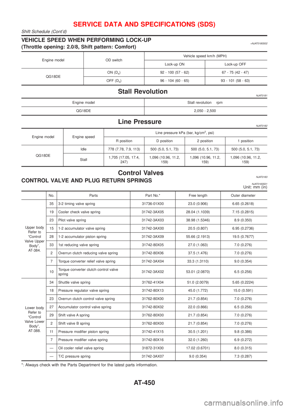
VEHICLE SPEED WHEN PERFORMING LOCK-UP=NJAT0180S02(Throttle opening: 2.0/8, Shift pattern: Comfort)
Engine model OD switchVehicle speed km/h (MPH)
Lock-up ON Lock-up OFF
QG18DEON (D
4) 92 - 100 (57 - 62) 67 - 75 (42 - 47)
OFF (D
3) 96 - 104 (60 - 65) 93 - 101 (58 - 63)
Stall RevolutionNJAT0181
Engine model Stall revolution rpm
QG18DE 2,050 - 2,500
Line PressureNJAT0182
Engine model Engine speedLine pressure kPa (bar, kg/cm
2, psi)
R position D position 2 position 1 position
QG18DEIdle 778 (7.78, 7.9, 113) 500 (5.0, 5.1, 73) 500 (5.0, 5.1, 73) 500 (5.0, 5.1, 73)
Stall1,705 (17.05, 17.4,
247)1,096 (10.96, 11.2,
159)1,096 (10.96, 11.2,
159)1,096 (10.96, 11.2,
159)
Control ValvesNJAT0183CONTROL VALVE AND PLUG RETURN SPRINGSNJAT0183S01Unit: mm (in)
No. Parts Part No.* Free length Outer diameter
Upper body
Refer to
ªControl
Valve Upper
Bodyº,
AT-384.35 3-2 timing valve spring 31736-01X00 23.0 (0.906) 6.65 (0.2618)
19 Cooler check valve spring 31742-3AX05 28.04 (1.1039) 7.15 (0.2815)
23 Pilot valve spring 31742-3AX03 38.98 (1.5346) 8.9 (0.350)
15 1-2 accumulator valve spring 31742-3AX00 20.5 (0.807) 6.95 (0.2736)
28 1-2 accumulator piston spring 31742-3AX09 55.66 (2.1913) 19.5 (0.7677)
33 1st reducing valve spring 31742-80X05 27.0 (1.063) 7.0 (0.276)
2 Overrun clutch reducing valve spring 31742-80X06 37.5 (1.476) 7.0 (0.276)
7 Torque converter relief valve spring 31742-3AX04 33.3 (1.3110) 9.0 (0.354)
10Torque converter clutch control valve
spring31742-3AX02 53.01 (2.0870) 6.5 (0.256)
Lower body
Refer to
ªControl
Valve Lower
Bodyº,
AT-388.34 Shuttle valve spring 31762-41X04 51.0 (2.0079) 5.65 (0.2224)
18 Pressure regulator valve spring 31742-80X13 45.0 (1.772) 15.0 (0.591)
23 Overrun clutch control valve spring 31762-80X00 21.7 (0.854) 7.0 (0.276)
27 Accumulator control valve spring 31742-80X02 22.0 (0.866) 6.5 (0.256)
29 Shift valve A spring 31762-80X00 21.7 (0.854) 7.0 (0.276)
2 Shift valve B spring 31762-80X00 21.7 (0.854) 7.0 (0.276)
11 Pressure modifier piston spring 31742-41X15 30.5 (1.201) 9.8 (0.386)
7 Pressure modifier valve spring 31742-80X16 32.0 (1.260) 6.9 (0.272)
Ð Oil cooler relief valve spring 31872-31X00 17.02 (0.6701) 8.0 (0.315)
Ð T/C pressure spring 31742-3AX07 9.0 (0.354) 7.3 (0.287)
*: Always check with the Parts Department for the latest parts information.
SERVICE DATA AND SPECIFICATIONS (SDS)
Shift Schedule (Cont'd)
AT-450
Page 1638 of 2493

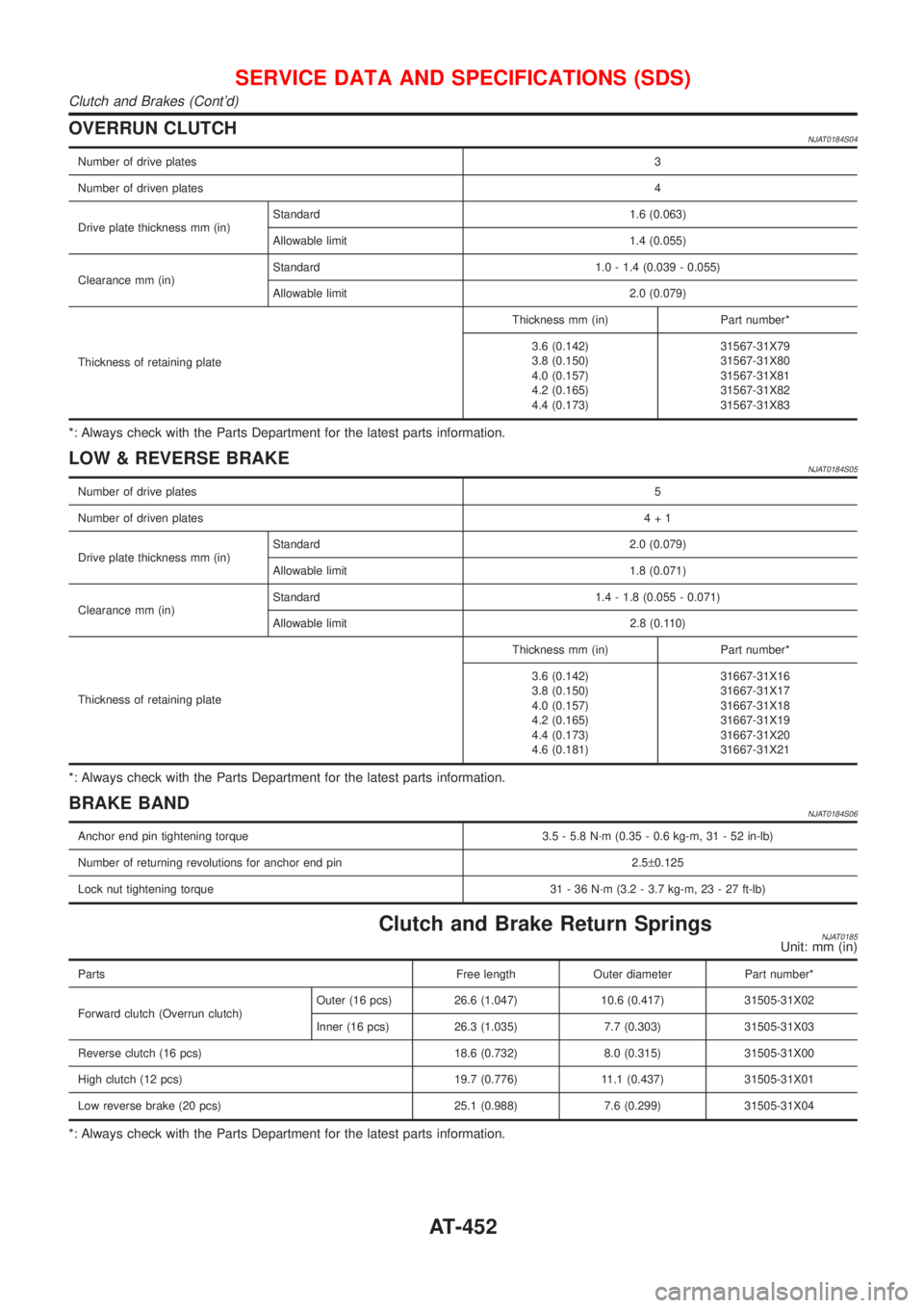
OVERRUN CLUTCHNJAT0184S04
Number of drive plates3
Number of driven plates4
Drive plate thickness mm (in)Standard 1.6 (0.063)
Allowable limit 1.4 (0.055)
Clearance mm (in)Standard 1.0 - 1.4 (0.039 - 0.055)
Allowable limit 2.0 (0.079)
Thickness of retaining plateThickness mm (in) Part number*
3.6 (0.142)
3.8 (0.150)
4.0 (0.157)
4.2 (0.165)
4.4 (0.173)31567-31X79
31567-31X80
31567-31X81
31567-31X82
31567-31X83
*: Always check with the Parts Department for the latest parts information.
LOW & REVERSE BRAKENJAT0184S05
Number of drive plates5
Number of driven plates4+1
Drive plate thickness mm (in)Standard 2.0 (0.079)
Allowable limit 1.8 (0.071)
Clearance mm (in)Standard 1.4 - 1.8 (0.055 - 0.071)
Allowable limit 2.8 (0.110)
Thickness of retaining plateThickness mm (in) Part number*
3.6 (0.142)
3.8 (0.150)
4.0 (0.157)
4.2 (0.165)
4.4 (0.173)
4.6 (0.181)31667-31X16
31667-31X17
31667-31X18
31667-31X19
31667-31X20
31667-31X21
*: Always check with the Parts Department for the latest parts information.
BRAKE BANDNJAT0184S06
Anchor end pin tightening torque 3.5 - 5.8 N´m (0.35 - 0.6 kg-m, 31 - 52 in-lb)
Number of returning revolutions for anchor end pin 2.5±0.125
Lock nut tightening torque 31 - 36 N´m (3.2 - 3.7 kg-m, 23 - 27 ft-lb)
Clutch and Brake Return SpringsNJAT0185Unit: mm (in)
Parts Free length Outer diameter Part number*
Forward clutch (Overrun clutch)Outer (16 pcs) 26.6 (1.047) 10.6 (0.417) 31505-31X02
Inner (16 pcs) 26.3 (1.035) 7.7 (0.303) 31505-31X03
Reverse clutch (16 pcs) 18.6 (0.732) 8.0 (0.315) 31505-31X00
High clutch (12 pcs) 19.7 (0.776) 11.1 (0.437) 31505-31X01
Low reverse brake (20 pcs) 25.1 (0.988) 7.6 (0.299) 31505-31X04
*: Always check with the Parts Department for the latest parts information.
SERVICE DATA AND SPECIFICATIONS (SDS)
Clutch and Brakes (Cont'd)
AT-452