2001 NISSAN ALMERA N16 relay
[x] Cancel search: relayPage 2261 of 2493
System Description=NJEL0497Refer to Owner's Manual for audio system operating instructions.
Power is supplied at all times
+through 15A fuse (No. 32, located in the fusible link and fuse block)
+to audio unit terminal 9
+to CD auto changer terminal 32.
With the ignition switch in the ACC or ON position, power is supplied
+through 10A fuse [No. 1, located in the fuse block (J/B)]
+to audio unit terminal 3,
+to CD auto changer terminal 36 and
Ground is supplied through the case of the audio unit.
Audio signals are supplied
+through audio unit terminals 7, 10, 11, 12, 13, 14, 15, 16
+to terminals 1 and 2 of front door speaker LH and RH,
+to terminals 1 and 2 of rear door speaker LH and RH and
+to terminals 1 and 2 of pillar tweeter LH and RH (with 6 speakers)
When the navigation system is triggered,
power is supplied
+through navi control unit terminal 46
+to speaker relay terminal 2
Ground is supplied
+through navi control unit terminal 44
+to speaker relay terminal 1
With power and ground supplied, the relay is energized, and then audio signal is interrupted to front door
speaker LH (LHD models) or RH (RHD models), and pillar tweeter LH (LHD models) or RH (RHD models)
For detailed, refer to ªNAVIGATION SYSTEMº.
NATS AUDIO LINKNJEL0497S01DescriptionNJEL0497S0101The link with the NATS IMMU implies that the audio unit can basically only be operated if connected to the
matching NATS IMMU to which the audio unit was initially fitted on the production line.
Since radio operation is impossible after the link with the NATS is disrupted theft of the audio unit is basically
useless since special equipment is required to reset the audio unit.
Initialization process for audio units that are linked to the NATS IMMU
New audio units will be delivered to the factories in the ªNEWº state, i.e. ready to be linked with the vehicle's
NATS. When the audio unit in ªNEWº state is first switched on at the factory, it will start up communication
with the vehicle's immobiliser control unit (IMMU) and send a code (the ªaudio unit Codeº) to the IMMU. The
IMMU will then store this code, which is unique to each audio unit, in its (permanent) memory.
Upon receipt of the code by the IMMU, the NATS will confirm correct receipt of the audio unit code to the audio
unit. Hereafter, the audio unit will operate as normal.
During the initialisation process, ªNEWº is displayed on the audio unit display. Normally though, communica-
tion between audio unit and IMMU takes such a short time (300 ms) that the audio unit seems to switch on
directly without showing ªNEWº on its display.
Normal operation
Each time the audio unit is switched on afterwards, the audio unit code will be verified between the audio unit
and the NATS before the audio unit becomes operational. During the code verification process, ªWAITº is
shown on the audio unit display. Again, the communication takes such a short time (300 ms) that the audio
unit seems to switch on directly without showing ªWAITº on its display.
When the radio is locked
In case of a audio unit being linked with the vehicle's NATS (immobilizer system), disconnection of the link
between the audio unit and the IMMU will cause the audio unit to switch into the lock (ªSECUREº) mode in
which the audio unit is fully inoperative. Hence, repair of the audio unit is basically impossible, unless the audio
unit is reset to the ªNEWº state for which special decoding equipment is required.
Clarion has provided their authorized service representatives with so called ªdecoder boxesº which can bring
the audio unit back to the ªNEWº state, enabling the audio unit to be switched on after which repair can be
AUDIO
System Description
EL-149
Page 2281 of 2493
System Description=NJEL0498Power is supplied at all times
+from 30A fusible link (letterE, located in the fuse and fusible link box)
+to circuit breaker terminal 1
+through circuit breaker terminal 2
+to power window relay terminal 5
With ignition switch in ON or START position, power is supplied
+through 10A fuse [No. 10, located in the fuse block (J/B)]
+to power window relay terminal 1
Ground is supplied to power window relay terminal 2
+through body grounds M28 and M67.
The power window relay is energized and power is supplied
+through power window relay terminal 3
+to power window main switch terminal 1,
+to front power window sub-switch terminal 5,
+to rear power window sub-switch LH and RH terminals 5 (models with rear power window).
MANUAL OPERATIONNJEL0498S01Front Door (Driver Side)NJEL0498S0101Ground is supplied
+to power window main switch terminal 3
+through body grounds M28 and M67.
WINDOW UP
When the driver's window switch in the power window main switch is pressed in the up position, power is
supplied
+through power window main switch terminal 9
+to driver side power window regulator terminal 1.
Ground is supplied
+through power window main switch terminal 2
+to driver side power window regulator terminal 8.
Then, the motor raises the window until the switch is released.
WINDOW DOWN
When the driver's window switch in the power window main switch is pressed in the down position, power is
supplied
+through power window main switch terminal 8
+to driver side power window regulator terminal 2.
Ground is supplied
+to driver side power window regulator terminal 1
+through power window main switch terminal 9.
Then, the motor lowers the window until the switch is released.
Front Door (Passenger Side)NJEL0498S0102Ground is supplied
+to power window main switch terminal 3
+through body grounds M28 and M67.
NOTE:
Numbers in parentheses are terminal numbers, when power window switch is pressed in the UP and DOWN
positions respectively.
POWER WINDOW MAIN SWITCH OPERATION
Power is supplied
+through power window main switch (5, 6)
+to front power window sub-switch (3, 4).
POWER WINDOW
System Description
EL-169
Page 2288 of 2493
Trouble DiagnosesNJEL0501
Symptom Possible cause Repair order
None of the power windows can be
operated using any switch.1. 10A fuse
2. 30A fusible link, M4 circuit
breaker
3. Power window relay
4. Ground circuit
5. Power window main switch1. Check 10A fuse [No. 10, located in fuse block (J/B)]
Turn ignition switch ªONº and verify positive battery
voltage is present at terminal 1 of power window
relay.
2. Check 30A fusible link (letterE, located in fuse and
fusible link box) and M4 circuit breaker. Verify posi-
tive battery voltage is present at terminal 5 of power
window relay.
3. Check power window relay.
4. Check the following:
a. Check ground circuit of power window main switch.
b. Check power window relay ground circuit.
5. Check power window main switch.
Driver side power window cannot
be operated but other windows can
be operated.1. Driver side power window regu-
lator circuit
2. Driver side power window regu-
lator
3. Power window main switch1. Check harness between power window main switch
and driver side power window regulator for open or
short circuit.
2. Check driver side power window regulator.
3. Check power window main switch.
One or more power windows
except driver's side window cannot
be operated.1. Power window sub-switches
2. Power window regulators
3. Power window main switch
4. Power window circuit1. Check power window sub-switch.
2. Check power window regulator.
3. Check power window main switch.
4. Check the following.
a. Check harness between the power window relay
terminal 3 and power window sub-switch terminal 5.
b. Check harnesses between power window main
switch and power window sub-switch for open/short
circuit.
c. Check harnesses between power window sub-switch
and power window regulator for open/short circuit.
Power windows except driver's
side window cannot be operated
using power window main switch
but can be operated by power win-
dow sub-switch.1. Power window main switch 1. Check power window main switch.
Driver side power window auto-
matic operation does not function
properly.1. Power window main switch 1. Check power window main switch.
POWER WINDOW
Trouble Diagnoses
EL-176
Page 2415 of 2493
Trouble Diagnoses=NJEL0525SYMPTOM CHARTNJEL0525S01
Symptom Diagnoses/service procedureReference
page
Any function of the system
does not operate.Check power supply and ground circuit for NAVI control unit. EL-306
Strange screen color or
unusual screen brightness.1. Check ªDisplay Settingº MODE. EL-296
2. Check display in ªDiagnose the Displayº MODE. EL-287
The display is not dimmed
when turning lighting switch
to ON.1. Check ªDisplay Settingº MODE. EL-296
2. Check lighting switch signal input to NAVI control unit correctly in ªDiagnosis for
the signals from the carº MODE.EL-285
No navigation guide voice
are heard from front driver
side speaker.1. Check ªGuide Volume Settingº. EL-300
2. Check speaker relay. EL-307
Beep does not sound when
the system guides route.Check ªBeep On/Offº MODE. EL-298
Position marker does not
trace along the route being
traveled.Go to ªWORK FLOW FOR NAVIGATION INSPECTIONº. EL-304
Position marker does not
indicate forward or backward
movement.Check reverse signal input to NAVI control unit correctly by ªDiagnosis for the sig-
nals from the carº MODE.EL-285
Radio wave of GPS cannot
be received. (GPS marker
on the display does not
become green color.)1. Is there anything obstructing the GPS antenna on the rear parcel finisher?
(GPS antenna located under the rear parcel finisher.)Ð
2. Check GPS radio wave receive condition in ªGPS Information MODEº. EL-294
3. Check GPS antenna in ªSelf Diagnosisº MODE. EL-279
Heading direction of position
marker does not match
vehicle direction.1. Perform ªAdjust Current Locationº MODE. EL-298
2. Go to ªWORK FLOW FOR NAVIGATION INSPECTIONº. EL-304
Stored location in the
address book and other
memory functions are lost
when battery is disconnected
or becomes discharged.Stored location in the address book and other memory functions may be lost if the
battery is disconnected or becomes discharged. If this should occur, charge or
replace the battery as necessary and re-enter the information.Ð
Map appears grey and can-
not be scrolled.The current location in the memory is out of the map data area. Perform ªInitialize
Locationº.EL-291
NAVIGATION SYSTEM
Trouble Diagnoses
EL-303
Page 2419 of 2493
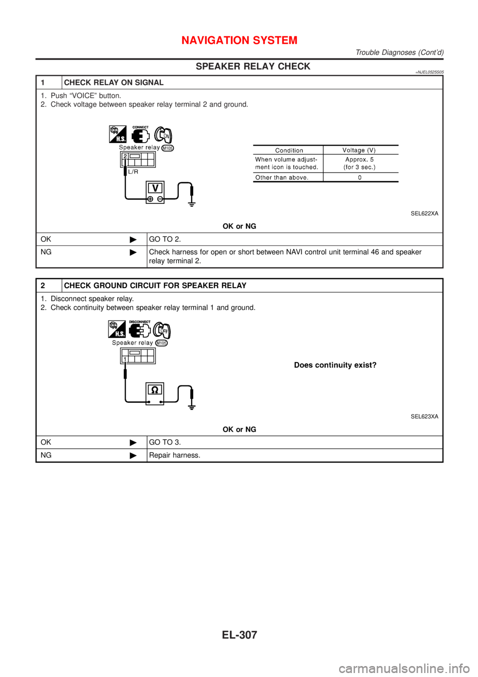
SPEAKER RELAY CHECK=NJEL0525S05
1 CHECK RELAY ON SIGNAL
1. Push ªVOICEº button.
2. Check voltage between speaker relay terminal 2 and ground.
SEL622XA
OK or NG
OK©GO TO 2.
NG©Check harness for open or short between NAVI control unit terminal 46 and speaker
relay terminal 2.
2 CHECK GROUND CIRCUIT FOR SPEAKER RELAY
1. Disconnect speaker relay.
2. Check continuity between speaker relay terminal 1 and ground.
SEL623XA
OK or NG
OK©GO TO 3.
NG©Repair harness.
NAVIGATION SYSTEM
Trouble Diagnoses (Cont'd)
EL-307
Page 2420 of 2493
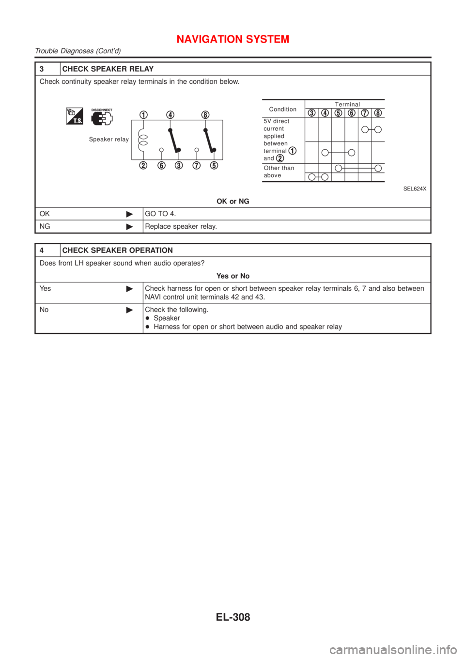
3 CHECK SPEAKER RELAY
Check continuity speaker relay terminals in the condition below.
Speaker relay
1
23
4
567
8ConditionTerminal
Other than
above
5V direct
current
applied
between
terminal
and
12
345678
SEL624X
OK or NG
OK©GO TO 4.
NG©Replace speaker relay.
4 CHECK SPEAKER OPERATION
Does front LH speaker sound when audio operates?
YesorNo
Ye s©Check harness for open or short between speaker relay terminals 6, 7 and also between
NAVI control unit terminals 42 and 43.
No©Check the following.
+Speaker
+Harness for open or short between audio and speaker relay
NAVIGATION SYSTEM
Trouble Diagnoses (Cont'd)
EL-308
Page 2436 of 2493
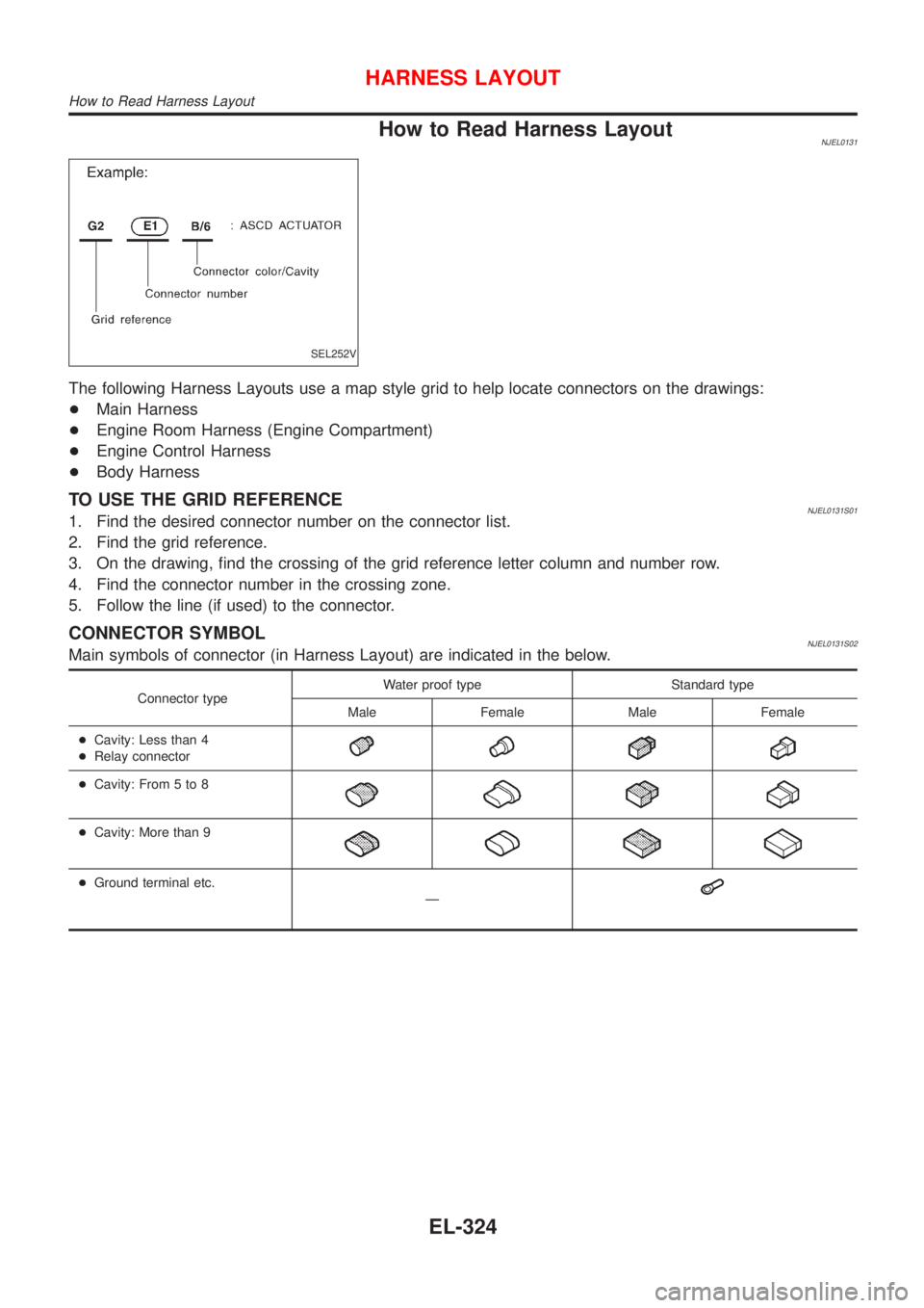
How to Read Harness LayoutNJEL0131
SEL252V
The following Harness Layouts use a map style grid to help locate connectors on the drawings:
+Main Harness
+Engine Room Harness (Engine Compartment)
+Engine Control Harness
+Body Harness
TO USE THE GRID REFERENCENJEL0131S011. Find the desired connector number on the connector list.
2. Find the grid reference.
3. On the drawing, find the crossing of the grid reference letter column and number row.
4. Find the connector number in the crossing zone.
5. Follow the line (if used) to the connector.
CONNECTOR SYMBOLNJEL0131S02Main symbols of connector (in Harness Layout) are indicated in the below.
Connector typeWater proof type Standard type
Male Female Male Female
+Cavity: Less than 4
+Relay connector
+Cavity: From 5 to 8
+Cavity: More than 9
+Ground terminal etc.
Ð
HARNESS LAYOUT
How to Read Harness Layout
EL-324
Page 2479 of 2493
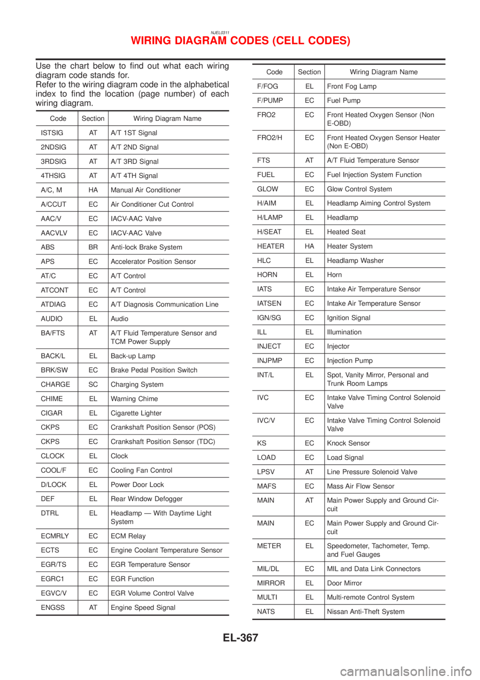
NJEL0311
Use the chart below to find out what each wiring
diagram code stands for.
Refer to the wiring diagram code in the alphabetical
index to find the location (page number) of each
wiring diagram.
Code Section Wiring Diagram Name
ISTSIG AT A/T 1ST Signal
2NDSIG AT A/T 2ND Signal
3RDSIG AT A/T 3RD Signal
4THSIG AT A/T 4TH Signal
A/C, M HA Manual Air Conditioner
A/CCUT EC Air Conditioner Cut Control
AAC/V EC IACV-AAC Valve
AACVLV EC IACV-AAC Valve
ABS BR Anti-lock Brake System
APS EC Accelerator Position Sensor
AT/C EC A/T Control
ATCONT EC A/T Control
ATDIAG EC A/T Diagnosis Communication Line
AUDIO EL Audio
BA/FTS AT A/T Fluid Temperature Sensor and
TCM Power Supply
BACK/L EL Back-up Lamp
BRK/SW EC Brake Pedal Position Switch
CHARGE SC Charging System
CHIME EL Warning Chime
CIGAR EL Cigarette Lighter
CKPS EC Crankshaft Position Sensor (POS)
CKPS EC Crankshaft Position Sensor (TDC)
CLOCK EL Clock
COOL/F EC Cooling Fan Control
D/LOCK EL Power Door Lock
DEF EL Rear Window Defogger
DTRL EL Headlamp Ð With Daytime Light
System
ECMRLY EC ECM Relay
ECTS EC Engine Coolant Temperature Sensor
EGR/TS EC EGR Temperature Sensor
EGRC1 EC EGR Function
EGVC/V EC EGR Volume Control Valve
ENGSS AT Engine Speed Signal
Code Section Wiring Diagram Name
F/FOG EL Front Fog Lamp
F/PUMP EC Fuel Pump
FRO2 EC Front Heated Oxygen Sensor (Non
E-OBD)
FRO2/H EC Front Heated Oxygen Sensor Heater
(Non E-OBD)
FTS AT A/T Fluid Temperature Sensor
FUEL EC Fuel Injection System Function
GLOW EC Glow Control System
H/AIM EL Headlamp Aiming Control System
H/LAMP EL Headlamp
H/SEAT EL Heated Seat
HEATER HA Heater System
HLC EL Headlamp Washer
HORN EL Horn
IATS EC Intake Air Temperature Sensor
IATSEN EC Intake Air Temperature Sensor
IGN/SG EC Ignition Signal
ILL EL Illumination
INJECT EC Injector
INJPMP EC Injection Pump
INT/L EL Spot, Vanity Mirror, Personal and
Trunk Room Lamps
IVC EC Intake Valve Timing Control Solenoid
Valve
IVC/V EC Intake Valve Timing Control Solenoid
Valve
KS EC Knock Sensor
LOAD EC Load Signal
LPSV AT Line Pressure Solenoid Valve
MAFS EC Mass Air Flow Sensor
MAIN AT Main Power Supply and Ground Cir-
cuit
MAIN EC Main Power Supply and Ground Cir-
cuit
METER EL Speedometer, Tachometer, Temp.
and Fuel Gauges
MIL/DL EC MIL and Data Link Connectors
MIRROR EL Door Mirror
MULTI EL Multi-remote Control System
NATS EL Nissan Anti-Theft System
WIRING DIAGRAM CODES (CELL CODES)
EL-367