2001 NISSAN ALMERA N16 relay
[x] Cancel search: relayPage 2089 of 2493
System DescriptionNJSC0004M/T MODELSNJSC0004S01Power is supplied at all times
+through 40A fusible link (letterB, located in the fuse and fusible link box)
+to ignition switch terminal 1.
With the ignition switch in START position, power is supplied
+from ignition switch terminal 5
+to starter motor harness connector terminal 1.
The starter motor plunger closes and provides a closed circuit between the battery and starter motor. The
starter motor is grounded to the engine block. With power and ground supplied, cranking occurs and the engine
starts.
A/T MODELSNJSC0004S02Power is supplied at all times
+through 40A fusible link (letterB, located in the fuse and fusible link box)
+to ignition switch terminal 1.
With the ignition switch in the START position, power is supplied
+from ignition switch terminal 5
+to park/neutral position relay terminal 5.
With the ignition switch ON or START position, power is supplied
+through 10A fuse [No. 20, located in the fuse block (J/B)]
+to park/neutral position (PNP) relay terminal 1.
With the selector lever in the P or N position, ground is supplied
+to park/neutral position relay terminal 2 through the park/neutral position switch
+from body grounds, F9 and F10.
Then park/neutral position relay is energized and power is supplied
+from park/neutral position relay terminal 3
+to starter motor harness connector terminal 1.
The starter motor plunger closes and provides a closed circuit between the battery and starter motor. The
starter motor is grounded to the engine block. With power and ground supplied, cranking occurs and the engine
starts.
STARTING SYSTEM
System Description
SC-13
Page 2113 of 2493
ELECTRICAL SYSTEM
SECTION
EL
CONTENTS
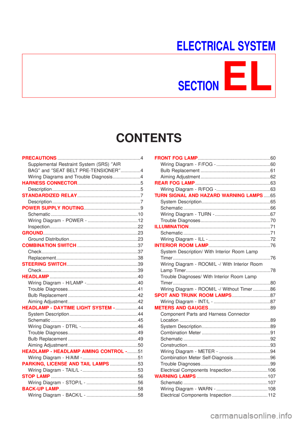
PRECAUTIONS...............................................................4
Supplemental Restraint System (SRS)²AIR
BAG²and²SEAT BELT PRE-TENSIONER²...............4
Wiring Diagrams and Trouble Diagnosis .....................4
HARNESS CONNECTOR................................................5
Description ...................................................................5
STANDARDIZED RELAY................................................7
Description ...................................................................7
POWER SUPPLY ROUTING...........................................9
Schematic ..................................................................10
Wiring Diagram - POWER - ......................................12
Inspection...................................................................22
GROUND........................................................................23
Ground Distribution ....................................................23
COMBINATION SWITCH..............................................37
Check .........................................................................37
Replacement ..............................................................38
STEERING SWITCH......................................................39
Check .........................................................................39
HEADLAMP...................................................................40
Wiring Diagram - H/LAMP -.......................................40
Trouble Diagnoses.....................................................41
Bulb Replacement .....................................................42
Aiming Adjustment .....................................................42
HEADLAMP - DAYTIME LIGHT SYSTEM -.................44
System Description ....................................................44
Schematic ..................................................................45
Wiring Diagram - DTRL - ...........................................46
Trouble Diagnoses.....................................................49
Bulb Replacement .....................................................49
Aiming Adjustment .....................................................50
HEADLAMP - HEADLAMP AIMING CONTROL -........51
Wiring Diagram - H/AIM - ..........................................51
PARKING, LICENSE AND TAIL LAMPS.....................53
Wiring Diagram - TAIL/L - ..........................................53
STOP LAMP..................................................................56
Wiring Diagram - STOP/L - .......................................56
BACK-UP LAMP............................................................58
Wiring Diagram - BACK/L - .......................................58FRONT FOG LAMP.......................................................60
Wiring Diagram - F/FOG - .........................................60
Bulb Replacement .....................................................61
Aiming Adjustment .....................................................62
REAR FOG LAMP.........................................................63
Wiring Diagram - R/FOG -.........................................63
TURN SIGNAL AND HAZARD WARNING LAMPS.....65
System Description ....................................................65
Schematic ..................................................................66
Wiring Diagram - TURN - ..........................................67
Trouble Diagnoses.....................................................70
ILLUMINATION..............................................................71
Schematic ..................................................................71
Wiring Diagram - ILL - ...............................................72
INTERIOR ROOM LAMP...............................................76
System Description/ With Interior Room Lamp
Timer ..........................................................................76
Wiring Diagram - ROOM/L -/ With Interior Room
Lamp Timer ................................................................78
Trouble Diagnoses/ With Interior Room Lamp
Timer ..........................................................................80
Wiring Diagram - ROOM/L -/ Without Timer .............86
SPOT AND TRUNK ROOM LAMPS.............................87
Wiring Diagram - INT/L - ...........................................87
METERS AND GAUGES...............................................89
Component Parts and Harness Connector
Location .....................................................................89
System Description ....................................................89
Combination Meter ....................................................91
Schematic ..................................................................92
Construction ...............................................................93
Wiring Diagram - METER - .......................................94
Combination Meter Self-Diagnosis ............................96
Trouble Diagnoses.....................................................99
Electrical Components Inspection ...........................106
WARNING LAMPS......................................................107
Schematic ................................................................107
Wiring Diagram - WARN - .......................................108
Electrical Components Inspection ........................... 112
Page 2119 of 2493
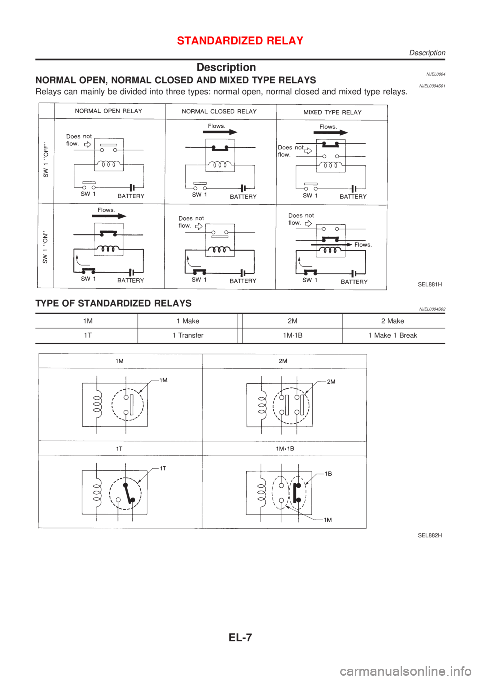
DescriptionNJEL0004NORMAL OPEN, NORMAL CLOSED AND MIXED TYPE RELAYSNJEL0004S01Relays can mainly be divided into three types: normal open, normal closed and mixed type relays.
SEL881H
TYPE OF STANDARDIZED RELAYSNJEL0004S02
1M 1 Make 2M 2 Make
1T 1 Transfer 1M´1B 1 Make 1 Break
SEL882H
STANDARDIZED RELAY
Description
EL-7
Page 2120 of 2493
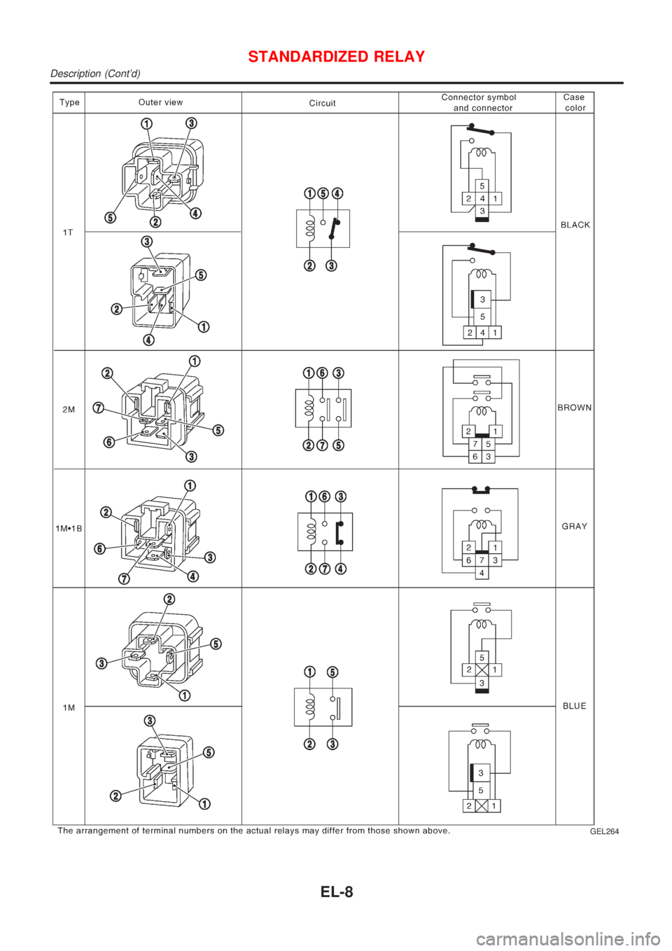
GEL264
STANDARDIZED RELAY
Description (Cont'd)
EL-8
Page 2235 of 2493
System DescriptionNJEL0456WIPER OPERATIONNJEL0456S01The wiper switch is controlled by a lever built into the combination switch.
There are three wiper switch positions:
+LO speed
+HI speed
+INT (Intermittent)
With the ignition switch in the ON or START position, power is supplied
+through 20A fuse [No. 25, located in the fuse block (J/B)]
+to front wiper motor terminal 5 and front wiper relay terminal 2.
Low and High Speed Wiper OperationNJEL0456S0101Ground is supplied to wiper and washer switch terminal 17 through body grounds E30 and E73.
When the wiper switch is placed in the LO position, ground is supplied
+through terminal 14 of the front wiper and washer switch
+to front wiper motor terminal 2.
With power and ground supplied, the wiper motor operates at low speed.
When the wiper switch is placed in the HI position, ground is supplied
+through terminal 16 of the front wiper and washer switch
+to wiper motor terminal 1.
With power and ground supplied, the wiper motor operates at high speed.
Auto Stop OperationNJEL0456S0102With wiper switch turned OFF, wiper motor will continue to operate until wiper arms reach windshield base.
When wiper arms are not located at base of windshield with wiper switch OFF, ground is provided
+from terminal 14 of the front wiper and washer switch
+to front wiper motor terminal 2, in order to continue wiper motor operation at low speed.
Ground is also supplied
+through terminal 13 of the front wiper and washer switch
+to front wiper relay terminal 3
+through terminal 4 of the front wiper relay.
+to front wiper motor terminal 3
+through terminal 4 of front wiper motor
+through body grounds E30 and E73.
When wiper arms reach base of windshield, front wiper motor terminals 3 and 5 are connected instead of ter-
minals 3 and 4. Wiper motor will then stop wiper arms at the STOP position.
Intermittent OperationNJEL0456S0103The front wiper motor operates the wiper arms one time at low speed at a set interval of approximately 1 to
13 seconds. This feature is controlled by the wiper amplifier (INT SW) combined with front wiper switch.
When the wiper switch is placed in the INT position, ground is supplied to wiper amplifier (WIPER SW INT)
and (ACC).
The desired interval time is input to wiper amplifier (INT VR) from wiper volume switch combined with front
wiper and washer switch.
Then intermittent ground is supplied
+from body grounds E30 and E73
+through terminal 5 of front wiper relay,
+through terminal 3 of front wiper relay,
+through terminal 13 of front wiper switch and,
+through terminal 14 of front wiper switch
+to terminal 2 of front wiper motor.
The desired interval time is input
+to front wiper relay terminal 1
+from terminal 20 of front wiper switch
FRONT WIPER AND WASHER
System Description
EL-123
Page 2250 of 2493
System Description=NJEL0463The rear window defogger system is controlled by the time control unit. The rear window defogger operates
only for approximately 15 minutes.
Power is supplied at all times
+through 20A fuse [No. 7, located in the fuse block (J/B)]
+to rear window defogger relay terminal 5 (B7 relay models) or 3 (B6 relay models)
+through 10A fuse [No. 13, located in the fuse block (J/B)]
+to rear window defogger relay terminal 6 (B6 relay models).
+through 15A fuse [No. 5, located in the fuse block (J/B)]
+to time control unit terminal 9.
With the ignition switch in the ON or START position, power is supplied
+through 10A fuse [No. 10, located in the fuse block (J/B)]
+to the rear window defogger relay terminal 1 and
+to time control unit terminal 1.
Ground is supplied to terminal 5 of the rear window defogger switch through body grounds M28 and M67.
When the rear defogger switch is turned ON, ground is supplied
+through terminal 3 of the rear defogger switch
+to time control unit terminal 3.
Terminal 13 of time control unit then supplies ground to the rear window defogger relay terminal 2.
With power and ground supplied, the rear window defogger relay is energized.
Power is supplied
+through terminals 5 and 7 of the rear window defogger relay (B6 relay models) or
+through terminal 3 of the rear window defogger relay (B7 relay models)
+to the rear window defogger and door mirror defogger.
The rear window defogger has an independent ground.
With power and ground supplied, the rear window defogger filaments heat and defog the rear window.
When the system is activated, the rear window defogger indicator illuminates in the rear window defogger
switch.
REAR WINDOW DEFOGGER
System Description
EL-138
Page 2255 of 2493
Trouble DiagnosesNJEL0465DIAGNOSTIC PROCEDURENJEL0465S01SYMPTOM: Rear window defogger does not activate, or does
not go off after activating.
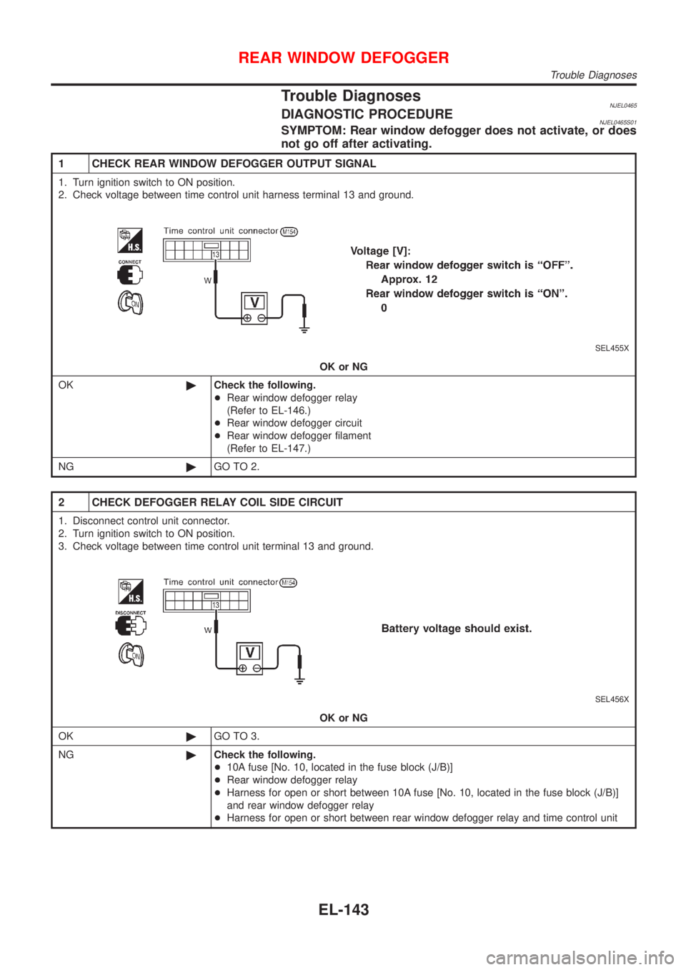
1 CHECK REAR WINDOW DEFOGGER OUTPUT SIGNAL
1. Turn ignition switch to ON position.
2. Check voltage between time control unit harness terminal 13 and ground.
SEL455X
OK or NG
OK©Check the following.
+Rear window defogger relay
(Refer to EL-146.)
+Rear window defogger circuit
+Rear window defogger filament
(Refer to EL-147.)
NG©GO TO 2.
2 CHECK DEFOGGER RELAY COIL SIDE CIRCUIT
1. Disconnect control unit connector.
2. Turn ignition switch to ON position.
3. Check voltage between time control unit terminal 13 and ground.
SEL456X
OK or NG
OK©GO TO 3.
NG©Check the following.
+10A fuse [No. 10, located in the fuse block (J/B)]
+Rear window defogger relay
+Harness for open or short between 10A fuse [No. 10, located in the fuse block (J/B)]
and rear window defogger relay
+Harness for open or short between rear window defogger relay and time control unit
REAR WINDOW DEFOGGER
Trouble Diagnoses
EL-143
Page 2258 of 2493
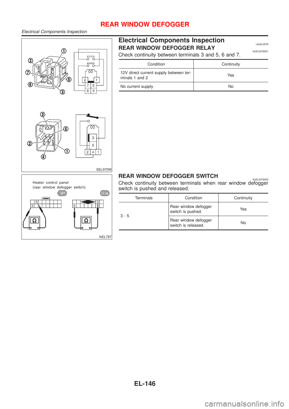
SEL970W
Electrical Components Inspection=NJEL0076REAR WINDOW DEFOGGER RELAYNJEL0076S01Check continuity between terminals 3 and 5, 6 and 7.
Condition Continuity
12V direct current supply between ter-
minals 1 and 2Ye s
No current supply No
NEL797
REAR WINDOW DEFOGGER SWITCHNJEL0076S02Check continuity between terminals when rear window defogger
switch is pushed and released.
Terminals Condition Continuity
3-5Rear window defogger
switch is pushed.Ye s
Rear window defogger
switch is released.No
REAR WINDOW DEFOGGER
Electrical Components Inspection
EL-146