Page 1759 of 2493
![NISSAN ALMERA N16 2001 Electronic Repair Manual Diagnostic item Diagnostic item is detected when ...Reference
Page
RR RH OUT ABS SOL
[SHORT]+Circuit for rear right outlet solenoid valve is shorted.
(An abnormally high output voltage is entered.)BR- NISSAN ALMERA N16 2001 Electronic Repair Manual Diagnostic item Diagnostic item is detected when ...Reference
Page
RR RH OUT ABS SOL
[SHORT]+Circuit for rear right outlet solenoid valve is shorted.
(An abnormally high output voltage is entered.)BR-](/manual-img/5/57351/w960_57351-1758.png)
Diagnostic item Diagnostic item is detected when ...Reference
Page
RR RH OUT ABS SOL
[SHORT]+Circuit for rear right outlet solenoid valve is shorted.
(An abnormally high output voltage is entered.)BR-72
RR LH OUT ABS SOL
[SHORT]+Circuit for rear left outlet solenoid valve is shorted.
(An abnormally high output voltage is entered.)BR-72
ABS ACTUATOR RELAY
[ABNORMAL]+Actuator solenoid valve relay is ON, even control unit sends off signal.
+Actuator solenoid valve relay is OFF, even control unit sends on signal.BR-72
ABS MOTOR RELAY
[ABNORMAL]+Circuit for actuator motor is open or shorted.
+Actuator motor relay is stuck.BR-75
BATTERY VOLT
[ABNORMAL]+Power source voltage supplied to ABS control unit is abnormally low. BR-77
CONTROL UNIT+Function of calculation in ABS control unit has failed. BR-79
*1: Be sure to confirm the ABS warning lamp illuminates when the ignition switch is turned ON after repairing the shorted sensor circuit,
but the lamp goes out when driving the vehicle over 30 km/h (19 MPH) for one minute in accordance with SELF-DIAGNOSIS
PROCEDURE.
PBR455D
DATA MONITOR PROCEDURENJBR0093S031. Turn ignition switch OFF.
2. Connect CONSULT-II to data link connector.
3. Turn ignition switch ON.
4. Touch ªSTARTº on CONSULT-II screen.
PBR385C
5. Touch ªABSº.
PST412B
6. Touch ªDATA MONITORº.
7. Touch ªSETTINGº on ªSELECT MONITOR ITEMº screen.
8. Touch ªLONG TIMEº on ªSET RECORDING CONDº screen.
9. Touch ªSTARTº on ªSELECT MONITOR ITEMº.
ON BOARD DIAGNOSTIC SYSTEM DESCRIPTIONABS
CONSULT-II Inspection Procedure (Cont'd)
BR-61
Page 1761 of 2493

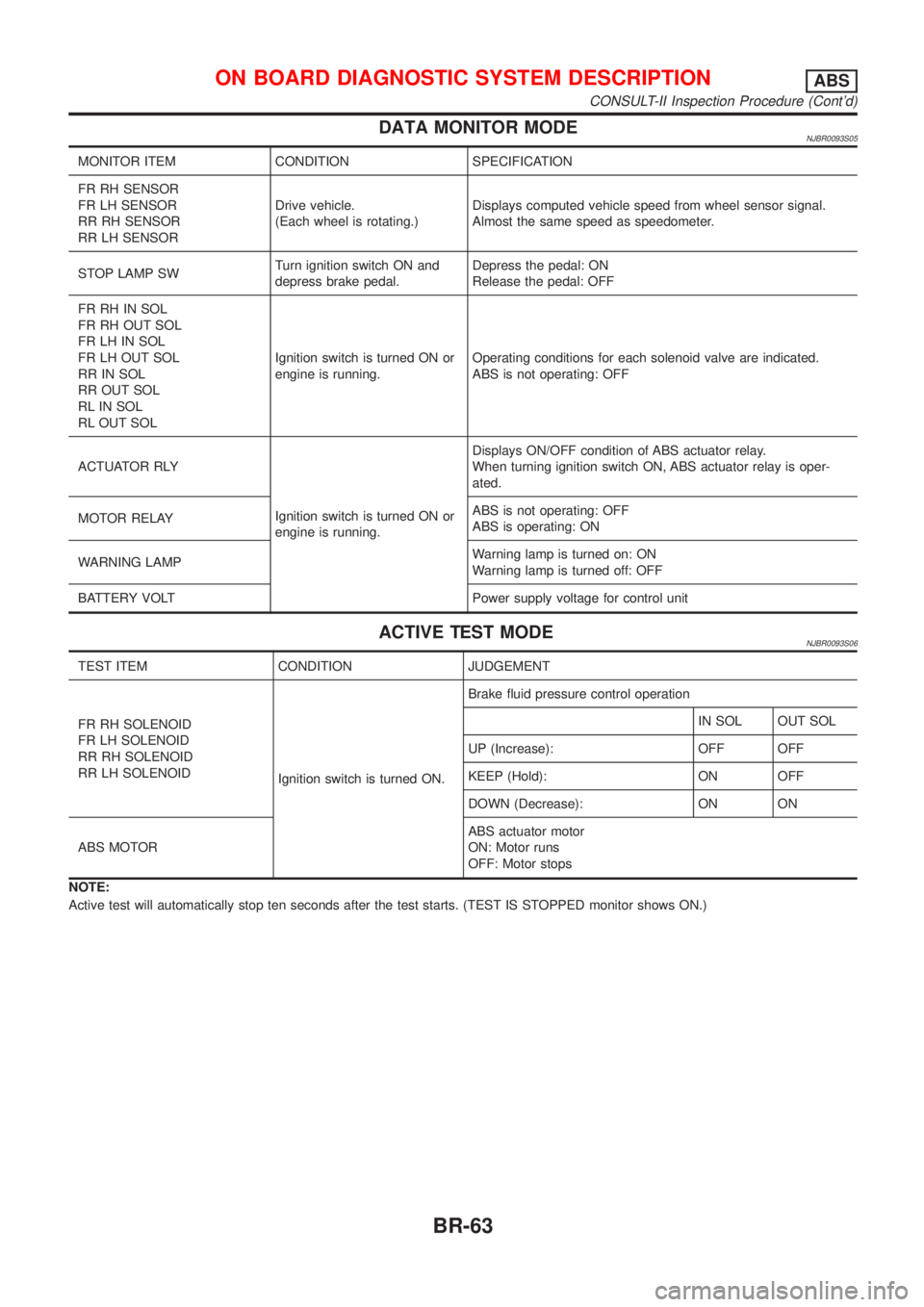
DATA MONITOR MODENJBR0093S05
MONITOR ITEM CONDITION SPECIFICATION
FR RH SENSOR
FR LH SENSOR
RR RH SENSOR
RR LH SENSORDrive vehicle.
(Each wheel is rotating.)Displays computed vehicle speed from wheel sensor signal.
Almost the same speed as speedometer.
STOP LAMP SWTurn ignition switch ON and
depress brake pedal.Depress the pedal: ON
Release the pedal: OFF
FR RH IN SOL
FR RH OUT SOL
FR LH IN SOL
FR LH OUT SOL
RR IN SOL
RR OUT SOL
RL IN SOL
RL OUT SOLIgnition switch is turned ON or
engine is running.Operating conditions for each solenoid valve are indicated.
ABS is not operating: OFF
ACTUATOR RLY
Ignition switch is turned ON or
engine is running.Displays ON/OFF condition of ABS actuator relay.
When turning ignition switch ON, ABS actuator relay is oper-
ated.
MOTOR RELAYABS is not operating: OFF
ABS is operating: ON
WARNING LAMPWarning lamp is turned on: ON
Warning lamp is turned off: OFF
BATTERY VOLT Power supply voltage for control unit
ACTIVE TEST MODENJBR0093S06
TEST ITEM CONDITION JUDGEMENT
FR RH SOLENOID
FR LH SOLENOID
RR RH SOLENOID
RR LH SOLENOID
Ignition switch is turned ON.Brake fluid pressure control operation
IN SOL OUT SOL
UP (Increase): OFF OFF
KEEP (Hold): ON OFF
DOWN (Decrease): ON ON
ABS MOTORABS actuator motor
ON: Motor runs
OFF: Motor stops
NOTE:
Active test will automatically stop ten seconds after the test starts. (TEST IS STOPPED monitor shows ON.)
ON BOARD DIAGNOSTIC SYSTEM DESCRIPTIONABS
CONSULT-II Inspection Procedure (Cont'd)
BR-63
Page 1770 of 2493
ABS Actuator Solenoid Valve or Solenoid Valve
Relay
=NJBR0100DIAGNOSTIC PROCEDURENJBR0100S01
1 INSPECTION START
Solenoid valve relay inspection
SBR761E
©GO TO 2.
2 CHECK SOLENOID VALVE POWER SUPPLY CIRCUIT
Check 40A [c] fusible link (ABS ACTR) for ABS solenoid valve relay. For fusible link layout, refer to POWER SUPPLY
ROUTING in EL section.
Is fusible link OK?
Ye s©GO TO 3.
No©GO TO 7.
3 CHECK FUSE
Check 10A fuse No. 31. For fuse layout, refer to ªPOWER SUPPLY ROUTINGº in EL section.
Is fuse OK?
Ye s©GO TO 4.
No©GO TO 9.
TROUBLE DIAGNOSES FOR SELF-DIAGNOSTIC ITEMSABS
ABS Actuator Solenoid Valve or Solenoid Valve Relay
BR-72
Page 1771 of 2493

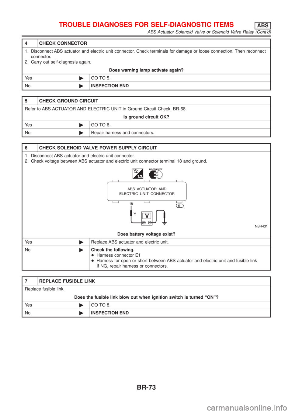
4 CHECK CONNECTOR
1. Disconnect ABS actuator and electric unit connector. Check terminals for damage or loose connection. Then reconnect
connector.
2. Carry out self-diagnosis again.
Does warning lamp activate again?
Ye s©GO TO 5.
No©INSPECTION END
5 CHECK GROUND CIRCUIT
Refer to ABS ACTUATOR AND ELECTRIC UNIT in Ground Circuit Check, BR-68.
Is ground circuit OK?
Ye s©GO TO 6.
No©Repair harness and connectors.
6 CHECK SOLENOID VALVE POWER SUPPLY CIRCUIT
1. Disconnect ABS actuator and electric unit connector.
2. Check voltage between ABS actuator and electric unit connector terminal 18 and ground.
NBR431
Does battery voltage exist?
Ye s©Replace ABS actuator and electric unit.
No©Check the following.
+Harness connector E1
+Harness for open or short between ABS actuator and electric unit and fusible link
If NG, repair harness or connectors.
7 REPLACE FUSIBLE LINK
Replace fusible link.
Does the fusible link blow out when ignition switch is turned ªONº?
Ye s©GO TO 8.
No©INSPECTION END
TROUBLE DIAGNOSES FOR SELF-DIAGNOSTIC ITEMSABS
ABS Actuator Solenoid Valve or Solenoid Valve Relay (Cont'd)
BR-73
Page 1772 of 2493
8 CHECK RELAY UNIT POWER SUPPLY CIRCUIT
1. Disconnect ABS actuator and electric unit connector.
2. Check continuity between ABS actuator and electric unit connector terminal 18 and ground.
NBR372
Does continuity exist?
Ye s©Replace ABS actuator and electric unit.
No©Check the following.
+Harness connector E1
+Harness for open or short between ABS actuator and electric unit and fusible link
If NG, repair harness or connectors.
9 REPLACE FUSE
Replace fuse.
Does the fuse blow out when ignition switch is turned ªONº?
Ye s©Check the following.
+Harness connector E1
+Harness for open or short between ABS actuator and electric unit and fuse
If NG, repair harness or connectors.
No©INSPECTION END
TROUBLE DIAGNOSES FOR SELF-DIAGNOSTIC ITEMSABS
ABS Actuator Solenoid Valve or Solenoid Valve Relay (Cont'd)
BR-74
Page 1773 of 2493
Motor Relay or Motor=NJBR0101DIAGNOSTIC PROCEDURENJBR0101S01
1 INSPECTION START
ABS motor relay inspection
SBR760E
©GO TO 2.
2 CHECK MOTOR POWER SUPPLY CIRCUIT
Check 40A [F] fusible link (ABS MTR) for ABS motor relay. For fusible link layout, refer to POWER SUPPLY ROUTING in
EL section.
Is fusible link OK?
Ye s©GO TO 3.
No©GO TO 6.
3 CHECK CONNECTOR
1. Disconnect ABS actuator and electric unit connector. Check terminals for damage or loose connection. Then reconnect
connectors.
2. Carry out self-diagnosis again.
Does warning lamp activate again?
Ye s©GO TO 4.
No©INSPECTION END
TROUBLE DIAGNOSES FOR SELF-DIAGNOSTIC ITEMSABS
Motor Relay or Motor
BR-75
Page 1774 of 2493

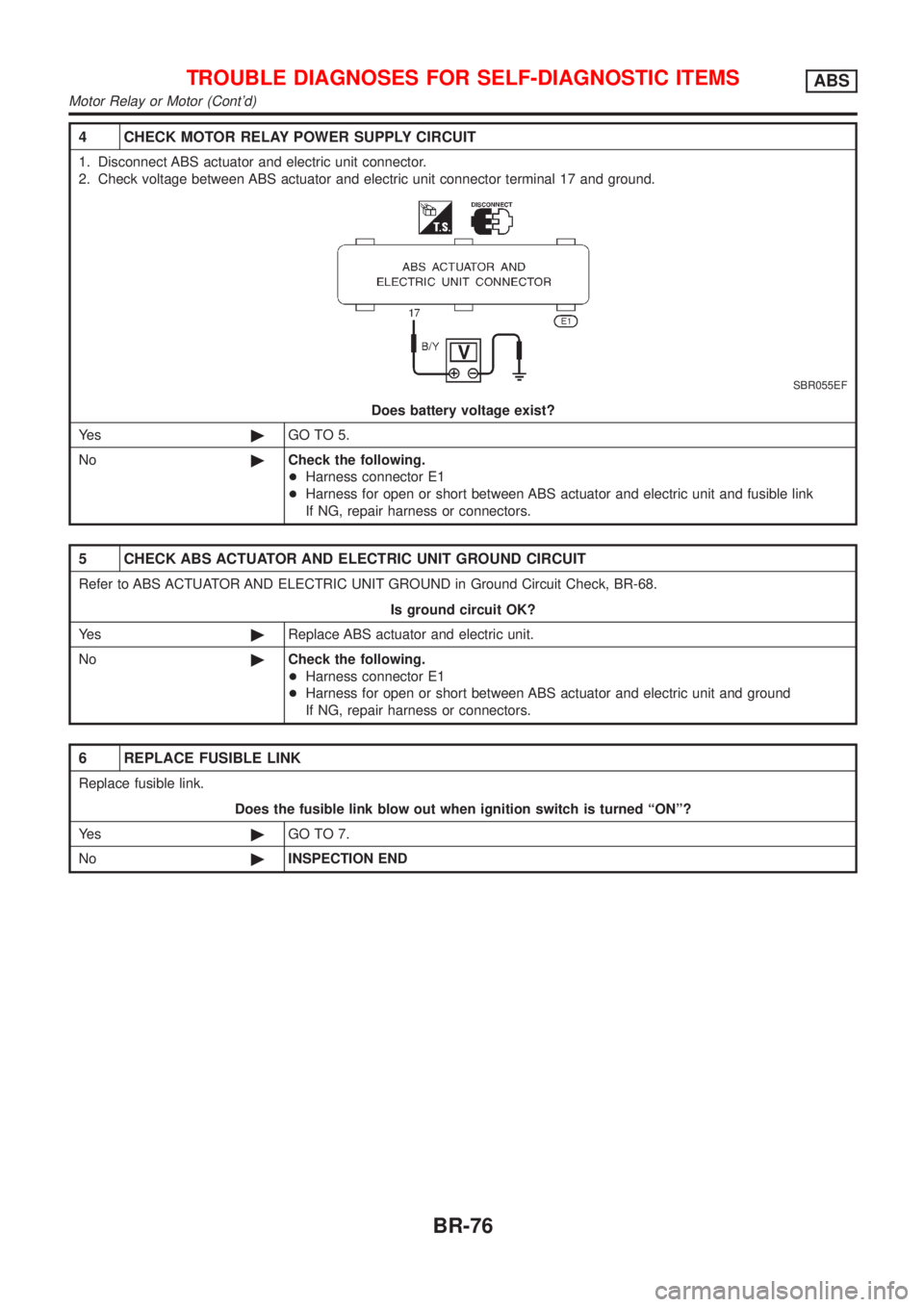
4 CHECK MOTOR RELAY POWER SUPPLY CIRCUIT
1. Disconnect ABS actuator and electric unit connector.
2. Check voltage between ABS actuator and electric unit connector terminal 17 and ground.
SBR055EF
Does battery voltage exist?
Ye s©GO TO 5.
No©Check the following.
+Harness connector E1
+Harness for open or short between ABS actuator and electric unit and fusible link
If NG, repair harness or connectors.
5 CHECK ABS ACTUATOR AND ELECTRIC UNIT GROUND CIRCUIT
Refer to ABS ACTUATOR AND ELECTRIC UNIT GROUND in Ground Circuit Check, BR-68.
Is ground circuit OK?
Ye s©Replace ABS actuator and electric unit.
No©Check the following.
+Harness connector E1
+Harness for open or short between ABS actuator and electric unit and ground
If NG, repair harness or connectors.
6 REPLACE FUSIBLE LINK
Replace fusible link.
Does the fusible link blow out when ignition switch is turned ªONº?
Ye s©GO TO 7.
No©INSPECTION END
TROUBLE DIAGNOSES FOR SELF-DIAGNOSTIC ITEMSABS
Motor Relay or Motor (Cont'd)
BR-76
Page 1775 of 2493
7 CHECK ABS ACTUATOR MOTOR POWER SUPPLY CIRCUIT
1. Disconnect battery cable and ABS actuator and electric unit connector.
2. Check continuity between ABS actuator and electric unit connector terminal 17 and ground.
NBR373
Does continuity exist?
Ye s©Check ABS actuator and electric unit pin terminals for damage or the connection of ABS
actuator and electric unit harness connector. Reconnect ABS actuator and electric unit
harness connector. Then retest.
No©Check the following.
+Harness connector E1
+Harness for open or short between ABS actuator and electric unit and fusible link
If NG, repair harness or connectors.
Low VoltageNJBR0102DIAGNOSTIC PROCEDURENJBR0102S01
1 INSPECTION START
ABS actuator and electric unit power supply and ground circuit inspection
SBR625E
©GO TO 2.
TROUBLE DIAGNOSES FOR SELF-DIAGNOSTIC ITEMSABS
Motor Relay or Motor (Cont'd)
BR-77