2001 NISSAN ALMERA N16 relay
[x] Cancel search: relayPage 974 of 2493
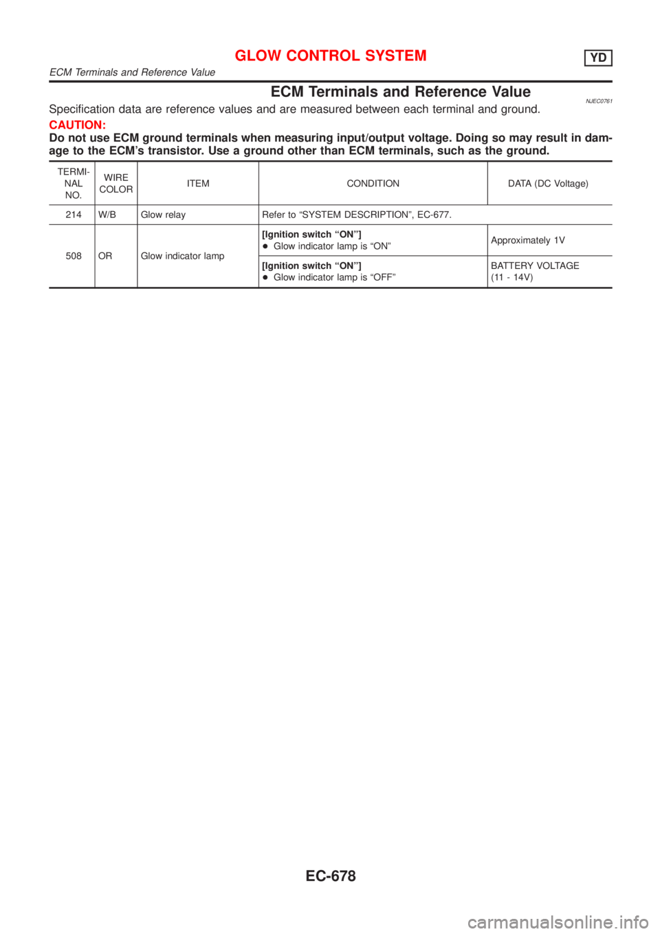
ECM Terminals and Reference ValueNJEC0761Specification data are reference values and are measured between each terminal and ground.
CAUTION:
Do not use ECM ground terminals when measuring input/output voltage. Doing so may result in dam-
age to the ECM's transistor. Use a ground other than ECM terminals, such as the ground.
TERMI-
NAL
NO.WIRE
COLORITEM CONDITION DATA (DC Voltage)
214 W/B Glow relay Refer to ªSYSTEM DESCRIPTIONº, EC-677.
508 OR Glow indicator lamp[Ignition switch ªONº]
+Glow indicator lamp is ªONºApproximately 1V
[Ignition switch ªONº]
+Glow indicator lamp is ªOFFºBATTERY VOLTAGE
(11 - 14V)
GLOW CONTROL SYSTEMYD
ECM Terminals and Reference Value
EC-678
Page 979 of 2493
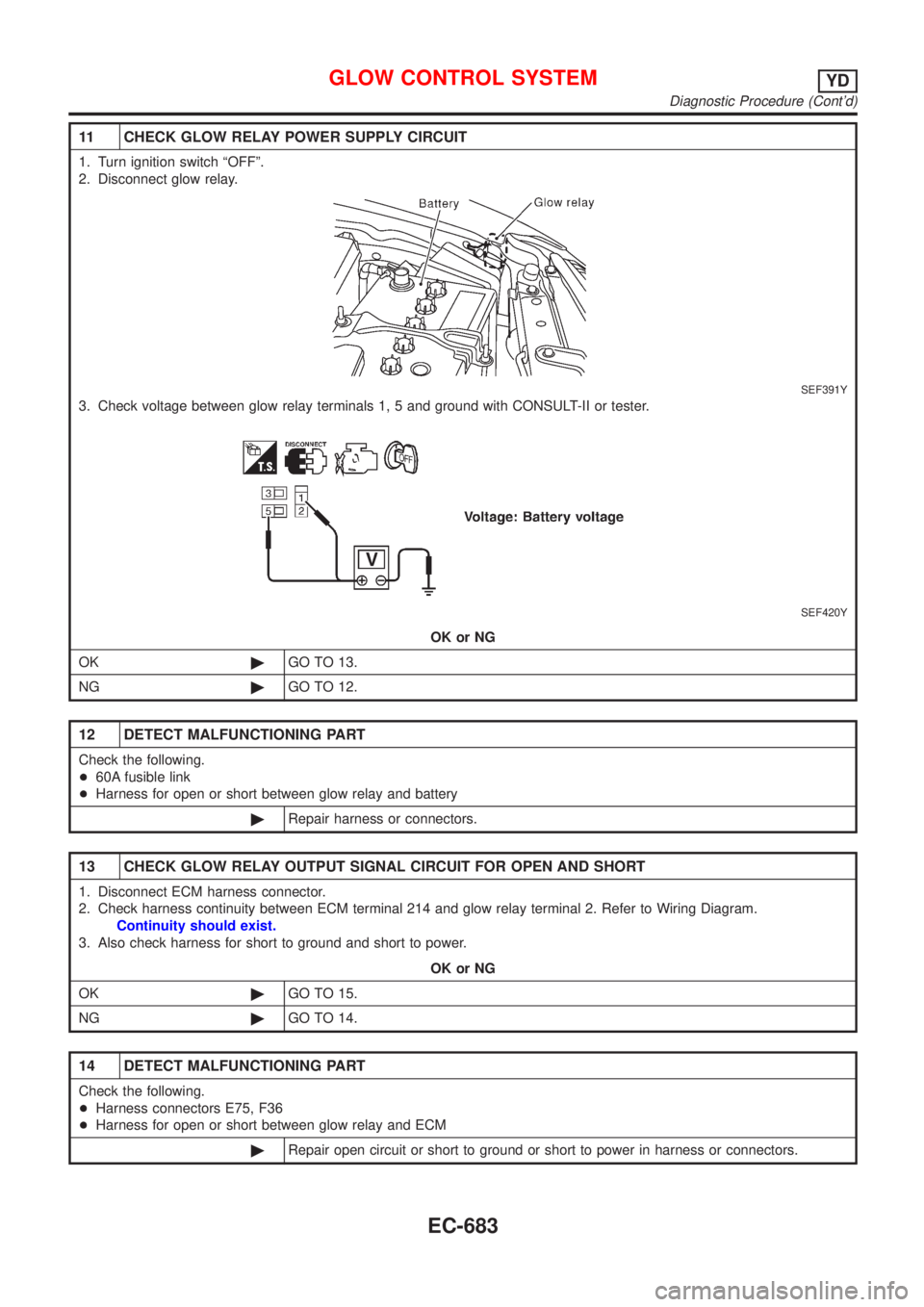
11 CHECK GLOW RELAY POWER SUPPLY CIRCUIT
1. Turn ignition switch ªOFFº.
2. Disconnect glow relay.
SEF391Y
3. Check voltage between glow relay terminals 1, 5 and ground with CONSULT-II or tester.
SEF420Y
OK or NG
OK©GO TO 13.
NG©GO TO 12.
12 DETECT MALFUNCTIONING PART
Check the following.
+60A fusible link
+Harness for open or short between glow relay and battery
©Repair harness or connectors.
13 CHECK GLOW RELAY OUTPUT SIGNAL CIRCUIT FOR OPEN AND SHORT
1. Disconnect ECM harness connector.
2. Check harness continuity between ECM terminal 214 and glow relay terminal 2. Refer to Wiring Diagram.
Continuity should exist.
3. Also check harness for short to ground and short to power.
OK or NG
OK©GO TO 15.
NG©GO TO 14.
14 DETECT MALFUNCTIONING PART
Check the following.
+Harness connectors E75, F36
+Harness for open or short between glow relay and ECM
©Repair open circuit or short to ground or short to power in harness or connectors.
GLOW CONTROL SYSTEMYD
Diagnostic Procedure (Cont'd)
EC-683
Page 980 of 2493
15 CHECK HARNESS CONTINUITY BETWEEN GLOW RELAY AND GLOW PLUG FOR OPEN AND SHORT
1. Disconnect glow plug harness connector.
2. Check harness continuity between glow relay terminal 3 and glow plug harness connector. Refer to Wiring Diagram.
Continuity should exist.
3. Also check harness for short to ground and short to power.
OK or NG
OK©GO TO 16.
NG©Repair open circuit or short to ground or short to power in harness or connectors.
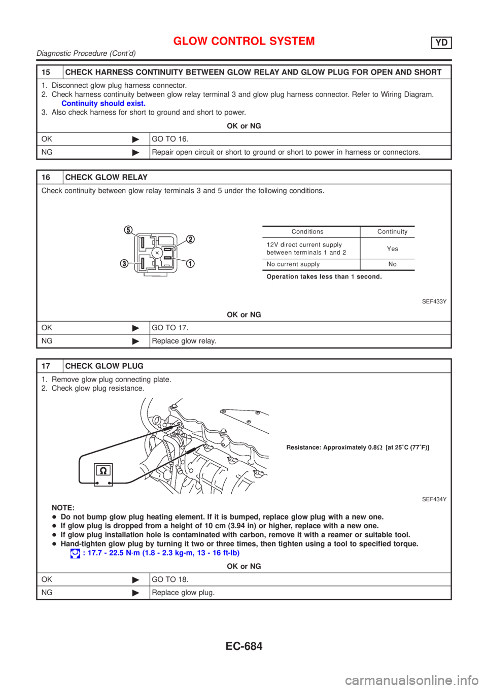
16 CHECK GLOW RELAY
Check continuity between glow relay terminals 3 and 5 under the following conditions.
SEF433Y
OK or NG
OK©GO TO 17.
NG©Replace glow relay.
17 CHECK GLOW PLUG
1. Remove glow plug connecting plate.
2. Check glow plug resistance.
SEF434Y
NOTE:
+Do not bump glow plug heating element. If it is bumped, replace glow plug with a new one.
+If glow plug is dropped from a height of 10 cm (3.94 in) or higher, replace with a new one.
+If glow plug installation hole is contaminated with carbon, remove it with a reamer or suitable tool.
+Hand-tighten glow plug by turning it two or three times, then tighten using a tool to specified torque.
: 17.7 - 22.5 N´m (1.8 - 2.3 kg-m, 13 - 16 ft-lb)
OK or NG
OK©GO TO 18.
NG©Replace glow plug.
GLOW CONTROL SYSTEMYD
Diagnostic Procedure (Cont'd)
EC-684
Page 986 of 2493
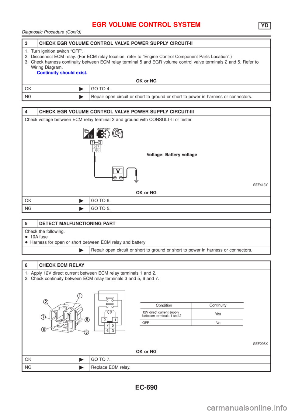
3 CHECK EGR VOLUME CONTROL VALVE POWER SUPPLY CIRCUIT-II
1. Turn ignition switch ªOFFº.
2. Disconnect ECM relay. (For ECM relay location, refer to ªEngine Control Component Parts Locationº.)
3. Check harness continuity between ECM relay terminal 5 and EGR volume control valve terminals 2 and 5. Refer to
Wiring Diagram.
Continuity should exist.
OK or NG
OK©GO TO 4.
NG©Repair open circuit or short to ground or short to power in harness or connectors.
4 CHECK EGR VOLUME CONTROL VALVE POWER SUPPLY CIRCUIT-III
Check voltage between ECM relay terminal 3 and ground with CONSULT-II or tester.
SEF413Y
OK or NG
OK©GO TO 6.
NG©GO TO 5.
5 DETECT MALFUNCTIONING PART
Check the following.
+10A fuse
+Harness for open or short between ECM relay and battery
©Repair open circuit or short to ground or short to power in harness or connectors.
6 CHECK ECM RELAY
1. Apply 12V direct current between ECM relay terminals 1 and 2.
2. Check continuity between ECM relay terminals 3 and 5, 6 and 7.
SEF296X
OK or NG
OK©GO TO 7.
NG©Replace ECM relay.
EGR VOLUME CONTROL SYSTEMYD
Diagnostic Procedure (Cont'd)
EC-690
Page 1525 of 2493
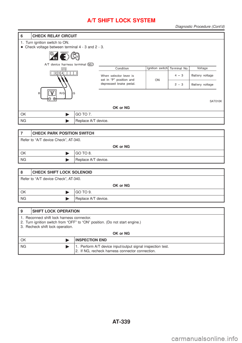
6 CHECK RELAY CIRCUIT
1. Turn ignition switch to ON.
+Check voltage between terminal4-3and2-3.
SAT010K
OK or NG
OK©GO TO 7.
NG©Replace A/T device.
7 CHECK PARK POSITION SWITCH
Refer to ªA/T device Checkº, AT-340.
OK or NG
OK©GO TO 8.
NG©Replace A/T device.
8 CHECK SHIFT LOCK SOLENOID
Refer to ªA/T device Checkº, AT-340.
OK or NG
OK©GO TO 9.
NG©Replace A/T device.
9 SHIFT LOCK OPERATION
1. Reconnect shift lock harness connector.
2. Turn ignition switch from ªOFFº to ªONº position. (Do not start engine.)
3. Recheck shift lock operation.
OK or NG
OK©INSPECTION END
NG©1. Perform A/T device input/output signal inspection test.
2. If NG, recheck harness connector connection.
A/T SHIFT LOCK SYSTEM
Diagnostic Procedure (Cont'd)
AT-339
Page 1700 of 2493

Inspection - Lining .....................................................33
Installation ..................................................................33
REAR DISC BRAKE (CAM & STRUT TYPE)..............35
Component ................................................................35
Pad Replacement ......................................................35
Removal .....................................................................37
Disassembly...............................................................37
Inspection...................................................................38
CALIPER.................................................................38
ROTOR...................................................................39
Assembly ...................................................................39
Installation ..................................................................42
REAR DISC BRAKE (BALL & RAMP TYPE)..............43
Component ................................................................43
Pad Replacement ......................................................43
Removal .....................................................................45
Disassembly...............................................................45
Inspection...................................................................45
CALIPER.................................................................45
ROTOR...................................................................46
Installation ..................................................................46
PARKING BRAKE CONTROL......................................47
Components...............................................................47
Removal and Installation ...........................................47
Inspection...................................................................47
Adjustment .................................................................48
ABS
DESCRIPTION...............................................................49
Purpose......................................................................49
ABS (Anti-Lock Brake System) Operation ................49
ABS Hydraulic Circuit ................................................49
System Components .................................................50
System Description ....................................................50
SENSOR.................................................................50
CONTROL UNIT......................................................50
ABS ACTUATOR AND ELECTRIC UNIT....................50
Component Parts and Harness Connector
Location .....................................................................52
Schematic ..................................................................53
Wiring Diagram - ABS - .............................................54
ON BOARD DIAGNOSTIC SYSTEM
DESCRIPTION...............................................................58
CONSULT-II ...............................................................58
CONSULT-II APPLICATION TO ABS..........................58
ECU (ABS CONTROL UNIT) PART NUMBER
MODE
.....................................................................58
CONSULT-II Inspection Procedure............................58
SELF-DIAGNOSIS PROCEDURE..............................58
SELF-DIAGNOSTIC RESULTS MODE.......................60
DATA MONITOR PROCEDURE................................61
ACTIVE TEST PROCEDURE....................................62
DATA MONITOR MODE...........................................63
ACTIVE TEST MODE...............................................63
TROUBLE DIAGNOSIS - INTRODUCTION..................64
How to Perform Trouble Diagnoses for Quick
and Accurate Repair ..................................................64
INTRODUCTION......................................................64
TROUBLE DIAGNOSIS - BASIC INSPECTION...........65
Preliminary Check......................................................65
Ground Circuit Check ................................................68
ABS ACTUATOR AND ELECTRIC UNIT GROUND.....68
TROUBLE DIAGNOSES FOR SELF-DIAGNOSTIC
ITEMS.............................................................................69
Wheel Sensor or Rotor ..............................................69
DIAGNOSTIC PROCEDURE.....................................69
ABS Actuator Solenoid Valve or Solenoid Valve
Relay ..........................................................................72
DIAGNOSTIC PROCEDURE.....................................72
Motor Relay or Motor.................................................75
DIAGNOSTIC PROCEDURE.....................................75
Low Voltage ...............................................................77
DIAGNOSTIC PROCEDURE.....................................77
Control Unit ................................................................79
DIAGNOSTIC PROCEDURE.....................................79
TROUBLE DIAGNOSES FOR SYMPTOMS.................80
1. ABS Works Frequently ..........................................80
2. Unexpected Pedal Action ......................................80
3. Long Stopping Distance ........................................81
4. ABS Does Not Work ..............................................82
5. Pedal Vibration and Noise.....................................83
6. ABS Warning Lamp Does Not Come On
When Ignition Switch Is Turned On...........................84
7. ABS Warning Lamp Stays On When Ignition
Switch Is Turned On ..................................................86
REMOVAL AND INSTALLATION.................................88
Wheel Sensors ..........................................................88
ABS Actuator and Electric Unit..................................89
REMOVAL...............................................................89
INSTALLATION........................................................89
Sensor Rotor..............................................................90
REMOVAL...............................................................90
INSTALLATION........................................................90
SERVICE DATA AND SPECIFICATIONS (SDS).........91
General Specifications ...............................................91
Disc Brake .................................................................91
Drum Brake................................................................91
Brake Pedal ...............................................................92
Parking Brake ............................................................92
CONTENTS(Cont'd)
BR-2
Page 1748 of 2493
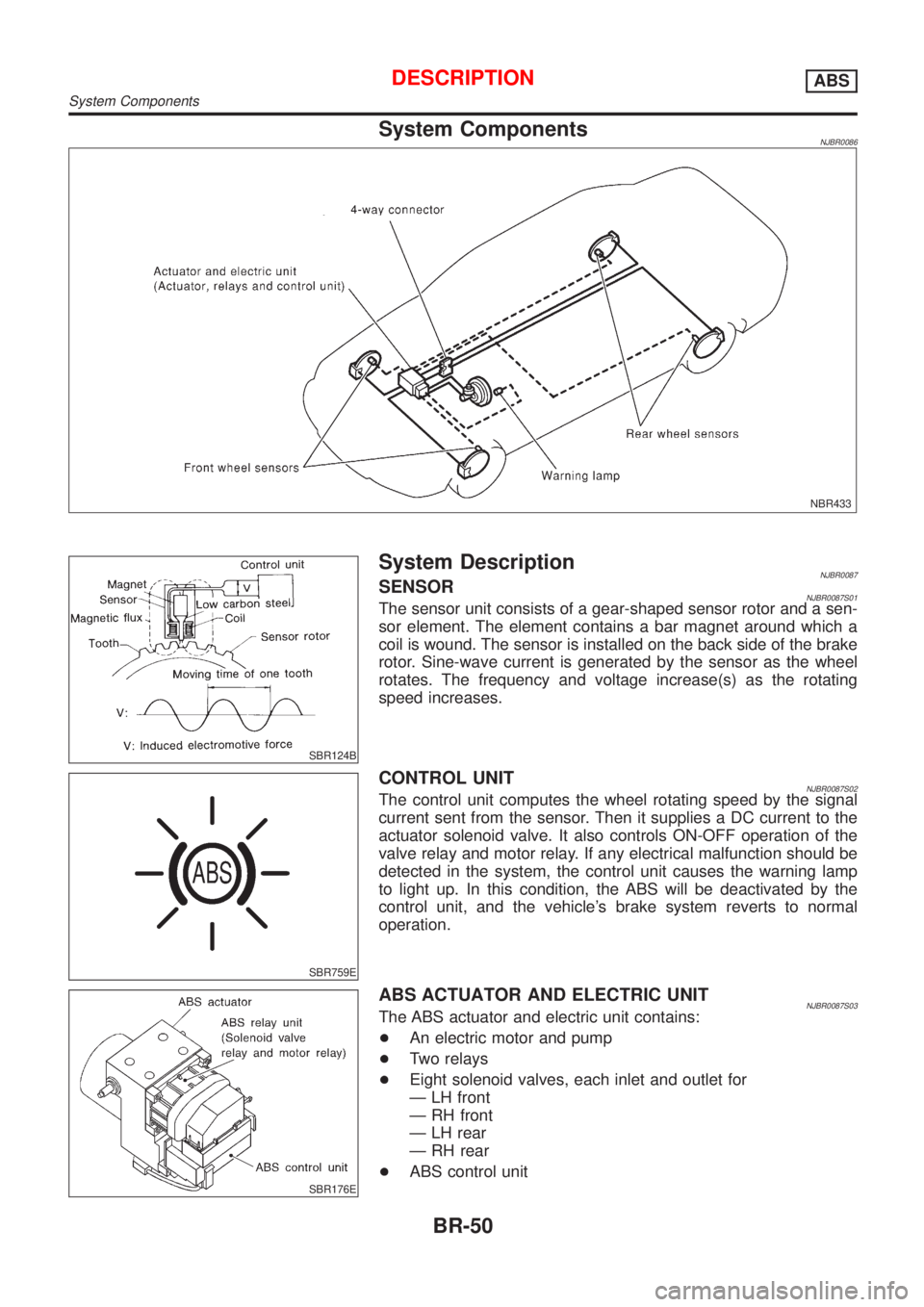
System ComponentsNJBR0086
NBR433
SBR124B
System DescriptionNJBR0087SENSORNJBR0087S01The sensor unit consists of a gear-shaped sensor rotor and a sen-
sor element. The element contains a bar magnet around which a
coil is wound. The sensor is installed on the back side of the brake
rotor. Sine-wave current is generated by the sensor as the wheel
rotates. The frequency and voltage increase(s) as the rotating
speed increases.
SBR759E
CONTROL UNITNJBR0087S02The control unit computes the wheel rotating speed by the signal
current sent from the sensor. Then it supplies a DC current to the
actuator solenoid valve. It also controls ON-OFF operation of the
valve relay and motor relay. If any electrical malfunction should be
detected in the system, the control unit causes the warning lamp
to light up. In this condition, the ABS will be deactivated by the
control unit, and the vehicle's brake system reverts to normal
operation.
SBR176E
ABS ACTUATOR AND ELECTRIC UNITNJBR0087S03The ABS actuator and electric unit contains:
+An electric motor and pump
+Two relays
+Eight solenoid valves, each inlet and outlet for
Ð LH front
Ð RH front
Ð LH rear
Ð RH rear
+ABS control unit
DESCRIPTIONABS
System Components
BR-50
Page 1756 of 2493
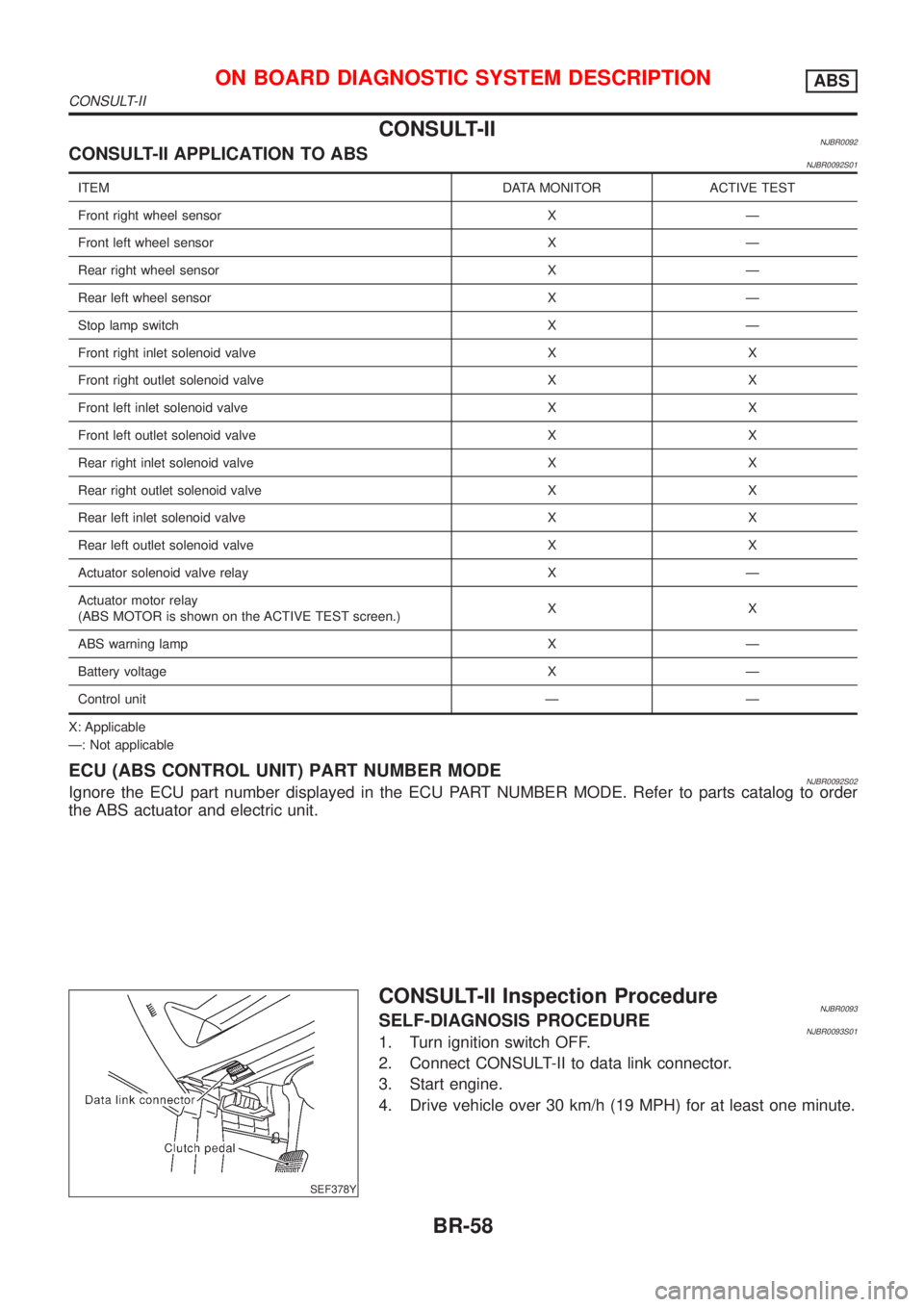
CONSULT-IINJBR0092CONSULT-II APPLICATION TO ABSNJBR0092S01
ITEM DATA MONITOR ACTIVE TEST
Front right wheel sensor X Ð
Front left wheel sensor X Ð
Rear right wheel sensor X Ð
Rear left wheel sensor X Ð
Stop lamp switch X Ð
Front right inlet solenoid valve X X
Front right outlet solenoid valve X X
Front left inlet solenoid valve X X
Front left outlet solenoid valve X X
Rear right inlet solenoid valve X X
Rear right outlet solenoid valve X X
Rear left inlet solenoid valve X X
Rear left outlet solenoid valve X X
Actuator solenoid valve relay X Ð
Actuator motor relay
(ABS MOTOR is shown on the ACTIVE TEST screen.)XX
ABS warning lamp X Ð
Battery voltage X Ð
Control unit Ð Ð
X: Applicable
Ð: Not applicable
ECU (ABS CONTROL UNIT) PART NUMBER MODENJBR0092S02Ignore the ECU part number displayed in the ECU PART NUMBER MODE. Refer to parts catalog to order
the ABS actuator and electric unit.
SEF378Y
CONSULT-II Inspection ProcedureNJBR0093SELF-DIAGNOSIS PROCEDURENJBR0093S011. Turn ignition switch OFF.
2. Connect CONSULT-II to data link connector.
3. Start engine.
4. Drive vehicle over 30 km/h (19 MPH) for at least one minute.
ON BOARD DIAGNOSTIC SYSTEM DESCRIPTIONABS
CONSULT-II
BR-58