Page 1650 of 2493
SFA898A
2. Remove brake caliper assembly and rotor.
Brake hose need not be disconnected from brake caliper. In
this case, suspend caliper assembly with wire so as not to
stretch brake hose. Be careful not to depress brake pedal, or
piston will pop out.
Make sure brake hose is not twisted.
SFA372-A
3. Separate tie-rod from knuckle with Tool.
Install stud nut on stud bolt to prevent damage to stud bolt.
SFA181A
4. Separate drive shaft from knuckle by lightly tapping it. If it is
hard to remove, use a puller.
Cover boots with shop towel so as not to damage them when
removing drive shaft.
SFA153B
5. Remove strut lower mounting bolts.
SFA113AC
6. Loosen lower ball joint tightening nut.
7. Separate knuckle from lower ball joint stud with Tool.
8. Remove knuckle from transverse link.
FRONT AXLE
Wheel Hub and Knuckle (Cont'd)
AX-6
Page 1655 of 2493
SFA090A
REMOVALNJAX00141. Remove wheel bearing lock nut.
Brake caliper need not be disconnected. Do not twist or
stretch brake hose when moving components.
SFA153B
2. Remove strut lower mount bolts.
3. Remove brake hose clip.
SFA499A
4. Separate drive shaft from knuckle by lightly tapping it. If it is
hard to remove, use a puller.
Cover boots with shop towel so as not to damage them
when removing drive shaft.
Refer to ªWheel Hub and Knuckleº, ªFRONT AXLEº, AX-5.
5. Remove right drive shaft from transaxle.
SAX012
6. Remove left drive shaft from transaxle.
Ð For M/T models Ð
+Pry off drive shaft from transaxle as shown at left.
FRONT AXLE
Drive Shaft (Cont'd)
AX-11
Page 1660 of 2493

Support BearingNJAX0018S05Make sure wheel bearing rolls freely and is free from noise, cracks,
pitting or wear.
Support Bearing BracketNJAX0018S06Check support bearing bracket for cracks with a magnetic explora-
tion or dyeing test.
ASSEMBLYNJAX0019+After drive shaft has been assembled, ensure that it
moves smoothly over its entire range without binding.
+Use NISSAN GENUINE GREASE or equivalent after every
overhaul.
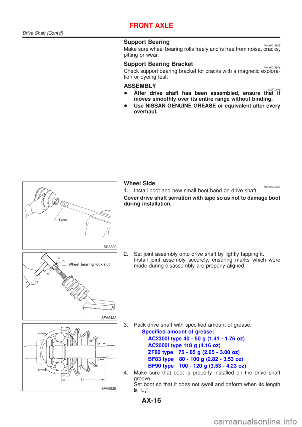
SFA800
Wheel SideNJAX0019S011. Install boot and new small boot band on drive shaft.
Cover drive shaft serration with tape so as not to damage boot
during installation.
SFA942A
2. Set joint assembly onto drive shaft by lightly tapping it.
Install joint assembly securely, ensuring marks which were
made during disassembly are properly aligned.
SFA592B
3. Pack drive shaft with specified amount of grease.
Specified amount of grease:
AC2300I type 40 - 50 g (1.41 - 1.76 oz)
AC2000I type 118 g (4.16 oz)
ZF80 type 75 - 85 g (2.65 - 3.00 oz)
BF83 type 80 - 100 g (2.82 - 3.53 oz)
BF90 type 100 - 120 g (3.53 - 4.23 oz)
4. Make sure that boot is properly installed on the drive shaft
groove.
Set boot so that it does not swell and deform when its length
is ªL
1º.
FRONT AXLE
Drive Shaft (Cont'd)
AX-16
Page 1684 of 2493

SFA449BB
+Install stabilizer bar with ball joint socket properly placed.
ARA027
+Check stabilizer for deformation or cracks. Replace if neces-
sary.
+Check rubber bushings for deterioration or cracks. Replace if
necessary.
+Check ball joint can rotate in all directions. If movement is not
smooth and free, replace stabilizer bar connecting rod.
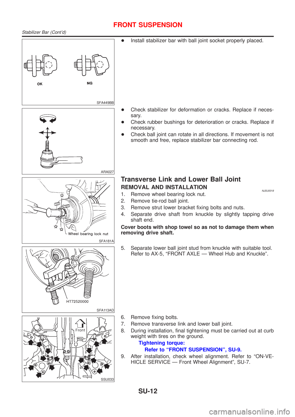
SFA181A
Transverse Link and Lower Ball Joint
REMOVAL AND INSTALLATIONNJSU00181. Remove wheel bearing lock nut.
2. Remove tie-rod ball joint.
3. Remove strut lower bracket fixing bolts and nuts.
4. Separate drive shaft from knuckle by slightly tapping drive
shaft end.
Cover boots with shop towel so as not to damage them when
removing drive shaft.
SFA113AD
5. Separate lower ball joint stud from knuckle with suitable tool.
Refer to AX-5, ªFRONT AXLE Ð Wheel Hub and Knuckleº.
SSU033
6. Remove fixing bolts.
7. Remove transverse link and lower ball joint.
8. During installation, final tightening must be carried out at curb
weight with tires on the ground.
Tightening torque:
Refer to ªFRONT SUSPENSIONº, SU-9.
9. After installation, check wheel alignment. Refer to ªON-VE-
HICLE SERVICE Ð Front Wheel Alignmentº, SU-7.
FRONT SUSPENSION
Stabilizer Bar (Cont'd)
SU-12
Page 1714 of 2493
SBR704C
InstallationNJBR0155CAUTION:
+Refill with new brake fluid ªDOT 4º.
+Never reuse drained brake fluid.
1. Place master cylinder onto brake booster and secure mount-
ing nuts lightly.
2. Torque mounting nuts.
: 12 - 15 N´m (1.2 - 1.5 kg-m,9-11ft-lb)
3. Fill up reservoir tank with new brake fluid.
4. Plug all ports on master cylinder with fingers to prevent air
suction while releasing brake pedal.
5. Have driver depress brake pedal slowly several times until no
air comes out of master cylinder.
6. Fit brake lines to master cylinder.
7. Tighten flare nuts.
: 15 - 18 N´m (1.5 - 1.8 kg-m, 11 - 13 ft-lb)
8. Bleed air from brake system. Refer to ªBleeding Brake
Systemº, BR-8.
MASTER CYLINDER (NABCO)
Installation
BR-16
Page 1717 of 2493
SBR236E
InstallationNJBR0121CAUTION:
+Refill with new brake fluid ªDOT 4º.
+Never reuse drained brake fluid.
1. Place master cylinder onto brake booster and secure mount-
ing nuts lightly.
2. Torque mounting nuts.
: 13 - 15 N´m (1.3 - 1.5 kg-m,9-11ft-lb)
3. Fill up reservoir tank with new brake fluid.
4. Plug all ports on master cylinder with fingers to prevent air
suction while releasing brake pedal.
5. Have driver depress brake pedal slowly several times until no
air comes out of master cylinder.
6. Fit brake lines to master cylinder.
7. Tighten flare nuts.
: 15 - 18 N´m (1.5 - 1.8 kg-m, 11 - 13 ft-lb)
8. Bleed air from brake system.
MASTER CYLINDER [BOSCH (NABCO)]
Installation
BR-19
Page 1718 of 2493

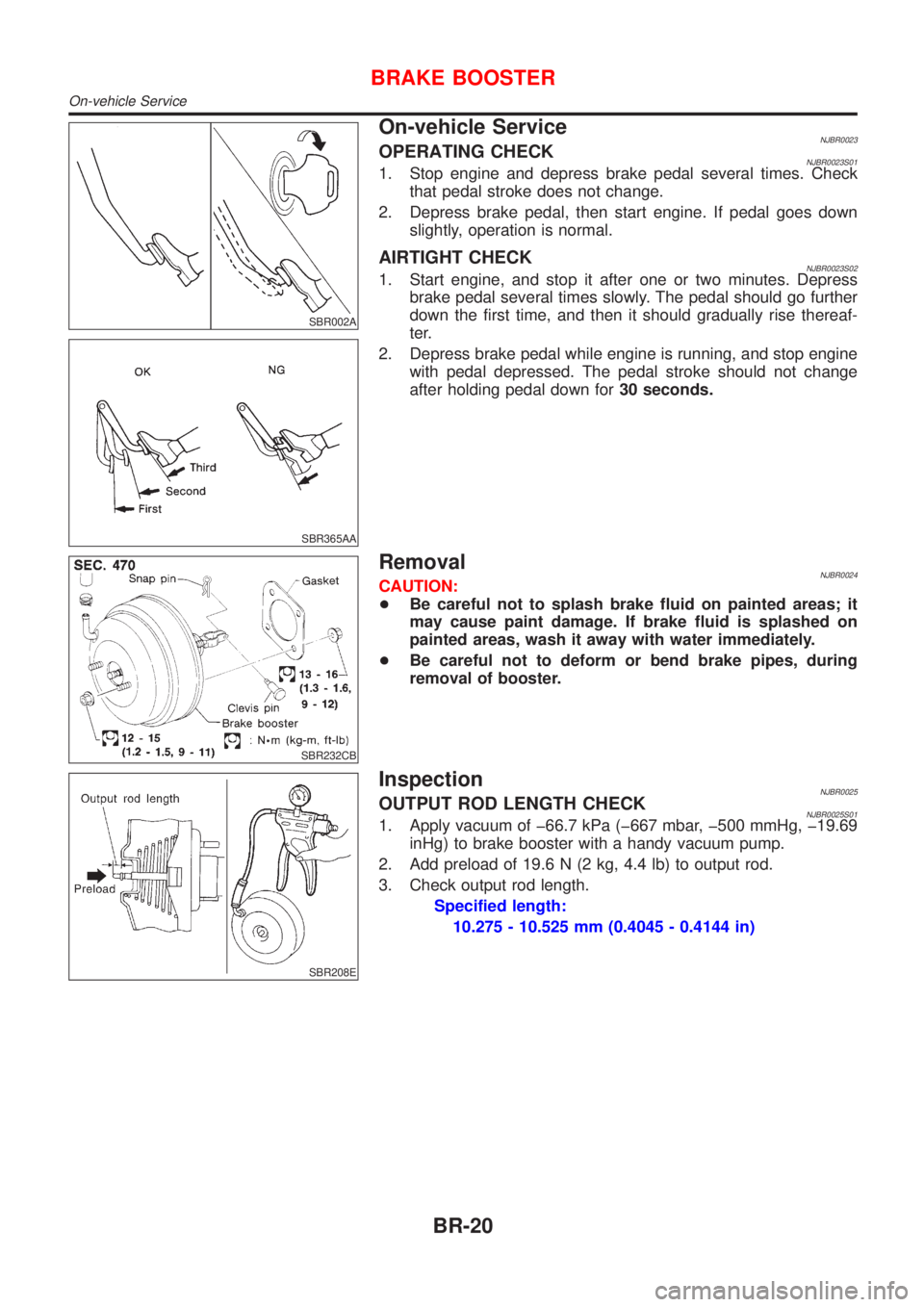
SBR002A
SBR365AA
On-vehicle ServiceNJBR0023OPERATING CHECKNJBR0023S011. Stop engine and depress brake pedal several times. Check
that pedal stroke does not change.
2. Depress brake pedal, then start engine. If pedal goes down
slightly, operation is normal.
AIRTIGHT CHECKNJBR0023S021. Start engine, and stop it after one or two minutes. Depress
brake pedal several times slowly. The pedal should go further
down the first time, and then it should gradually rise thereaf-
ter.
2. Depress brake pedal while engine is running, and stop engine
with pedal depressed. The pedal stroke should not change
after holding pedal down for30 seconds.
SBR232CB
RemovalNJBR0024CAUTION:
+Be careful not to splash brake fluid on painted areas; it
may cause paint damage. If brake fluid is splashed on
painted areas, wash it away with water immediately.
+Be careful not to deform or bend brake pipes, during
removal of booster.
SBR208E
InspectionNJBR0025OUTPUT ROD LENGTH CHECKNJBR0025S011. Apply vacuum of þ66.7 kPa (þ667 mbar, þ500 mmHg, þ19.69
inHg) to brake booster with a handy vacuum pump.
2. Add preload of 19.6 N (2 kg, 4.4 lb) to output rod.
3. Check output rod length.
Specified length:
10.275 - 10.525 mm (0.4045 - 0.4144 in)
BRAKE BOOSTER
On-vehicle Service
BR-20
Page 1719 of 2493
InstallationNJBR0026CAUTION:
+Be careful not to deform or bend brake pipes, during
installation of booster.
+Replace clevis pin if damaged.
+Refill with new brake fluid ªDOT 4º.
+Never reuse drained brake fluid.
+Take care not to damage brake booster mounting bolt
thread when installing. Due to the acute angle of
installation, the threads can be damaged with the dash
panel.
SBR237EA
1. Before fitting booster, temporarily adjust clevis to dimension
shown.
2. Fit booster, then secure mounting nuts (brake pedal bracket to
master cylinder) lightly.
3. Connect brake pedal and booster input rod with clevis pin.
4. Secure mounting nuts.
Specification:
13 - 16 N´m (1.3 - 1.6 kg-m,9-12ft-lb)
5. Install master cylinder. Refer to ªInstallationº in ªMASTER
CYLINDERº, BR-19.
6. Bleed air. Refer to ªBleeding Brake Systemº, BR-8.
BRAKE BOOSTER
Installation
BR-21