Page 1724 of 2493
lightly [approximately 9.8 N (1.0 kg, 2.2 lb)].
6. Remove thickness gauges (2).
+Leave sprocket retaining bolts (M6) until installation.
VACUUM PUMP
Assembly (Cont'd)
BR-26
Page 1748 of 2493

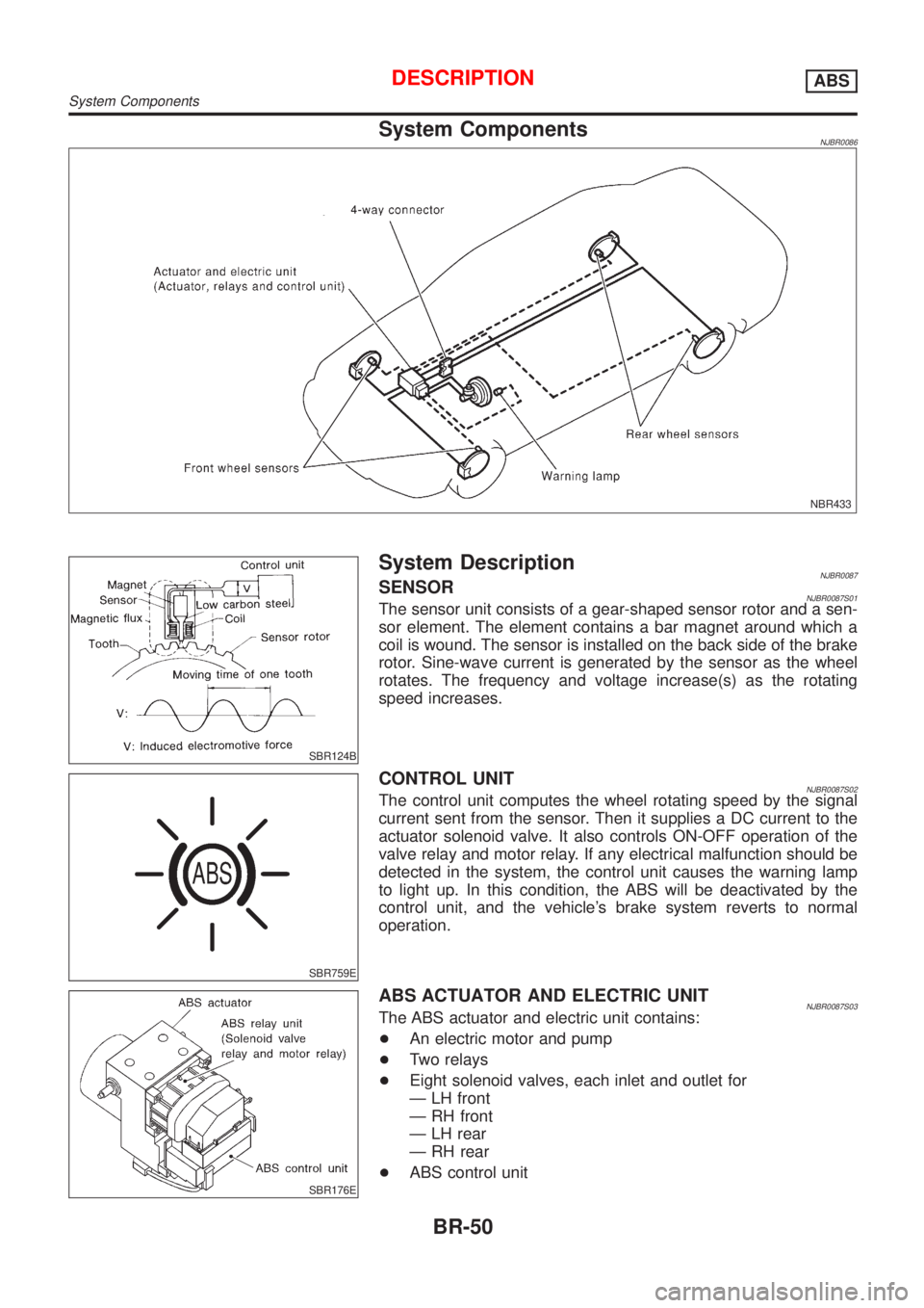
System ComponentsNJBR0086
NBR433
SBR124B
System DescriptionNJBR0087SENSORNJBR0087S01The sensor unit consists of a gear-shaped sensor rotor and a sen-
sor element. The element contains a bar magnet around which a
coil is wound. The sensor is installed on the back side of the brake
rotor. Sine-wave current is generated by the sensor as the wheel
rotates. The frequency and voltage increase(s) as the rotating
speed increases.
SBR759E
CONTROL UNITNJBR0087S02The control unit computes the wheel rotating speed by the signal
current sent from the sensor. Then it supplies a DC current to the
actuator solenoid valve. It also controls ON-OFF operation of the
valve relay and motor relay. If any electrical malfunction should be
detected in the system, the control unit causes the warning lamp
to light up. In this condition, the ABS will be deactivated by the
control unit, and the vehicle's brake system reverts to normal
operation.
SBR176E
ABS ACTUATOR AND ELECTRIC UNITNJBR0087S03The ABS actuator and electric unit contains:
+An electric motor and pump
+Two relays
+Eight solenoid valves, each inlet and outlet for
Ð LH front
Ð RH front
Ð LH rear
Ð RH rear
+ABS control unit
DESCRIPTIONABS
System Components
BR-50
Page 1798 of 2493

Bleeding Hydraulic SystemNJST00141. Raise front end of vehicle until wheels are clear of the ground.
2. Add fluid into oil tank to specified level. Then quickly turn steer-
ing wheel fully to right and left and lightly touch steering stop-
pers.
Repeat steering wheel operation until fluid level no longer
decreases.
3. Start engine.
Repeat step 2. above.
+Incomplete air bleeding will cause the following to occur. When
this happens, bleed air again.
a) Air bubbles in reservoir tank
b) Clicking noise in oil pump
c) Excessive buzzing in oil pump
Fluid noise may occur in the valve or oil pump. This is common
when the vehicle is stationary or while turning the steering wheel
slowly. This does not affect the performance or durability of the
system.
SST491B
SST090B
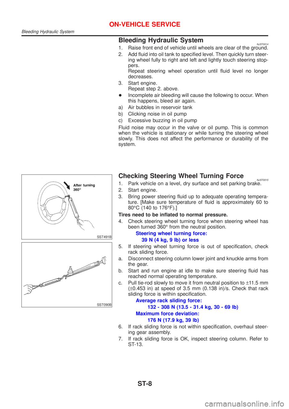
Checking Steering Wheel Turning ForceNJST00151. Park vehicle on a level, dry surface and set parking brake.
2. Start engine.
3. Bring power steering fluid up to adequate operating tempera-
ture. [Make sure temperature of fluid is approximately 60 to
80ÉC (140 to 176ÉF).]
Tires need to be inflated to normal pressure.
4. Check steering wheel turning force when steering wheel has
been turned 360É from the neutral position.
Steering wheel turning force:
39 N (4 kg, 9 lb) or less
5. If steering wheel turning force is out of specification, check
rack sliding force.
a. Disconnect steering column lower joint and knuckle arms from
the gear.
b. Start and run engine at idle to make sure steering fluid has
reached normal operating temperature.
c. Pull tie-rod slowly to move it from neutral position to±11.5 mm
(±0.453 in) at speed of 3.5 mm (0.138 in)/s. Check that rack
sliding force is within specification.
Average rack sliding force:
132 - 308 N (13.5 - 31.4 kg, 30 - 69 lb)
Maximum force deviation:
176 N (17.9 kg, 39 lb)
6. If rack sliding force is not within specification, overhaul steer-
ing gear assembly.
7. If rack sliding force is OK, inspect steering column. Refer to
ST-13.
ON-VEHICLE SERVICE
Bleeding Hydraulic System
ST-8
Page 1804 of 2493
SST742A
b) Install new self-shear type screws and then cut off self-shear
type screw heads.
SST855C
InspectionNJST0020+When steering wheel does not turn smoothly, check the steer-
ing column as follows and replace damaged parts.
a) Check column bearings for damage or unevenness. Lubricate
with recommended multi-purpose grease or replace steering
column as an assembly, if necessary.
b) Check jacket tube for deformation or breakage. Replace if
necessary.
+When the vehicle comes into a light collision, check length ªLº.
Steering column length ªLº:
Refer to SDS, ST-29.
If out of the specifications, replace steering column as an assem-
bly.
SST582B
TILT MECHANISMNJST0020S01+After installing steering column, check tilt mechanism opera-
tion.
STEERING WHEEL AND STEERING COLUMN
Disassembly and Assembly (Cont'd)
ST-14
Page 1812 of 2493

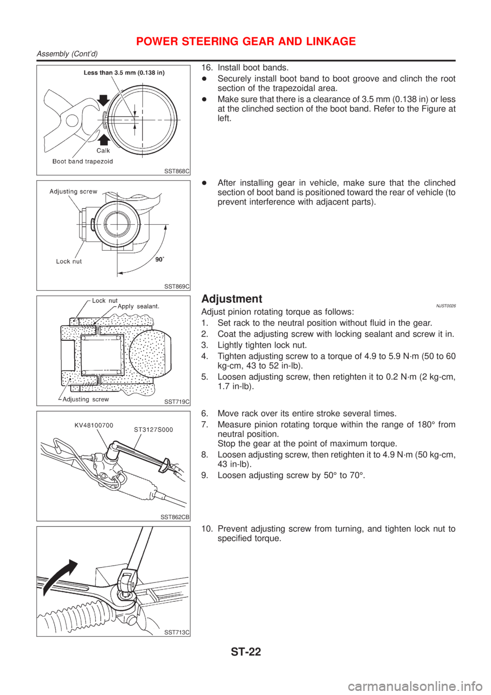
SST868C
16. Install boot bands.
+Securely install boot band to boot groove and clinch the root
section of the trapezoidal area.
+Make sure that there is a clearance of 3.5 mm (0.138 in) or less
at the clinched section of the boot band. Refer to the Figure at
left.
SST869C
+After installing gear in vehicle, make sure that the clinched
section of boot band is positioned toward the rear of vehicle (to
prevent interference with adjacent parts).
SST719C
AdjustmentNJST0026Adjust pinion rotating torque as follows:
1. Set rack to the neutral position without fluid in the gear.
2. Coat the adjusting screw with locking sealant and screw it in.
3. Lightly tighten lock nut.
4. Tighten adjusting screw to a torque of 4.9 to 5.9 N´m (50 to 60
kg-cm, 43 to 52 in-lb).
5. Loosen adjusting screw, then retighten it to 0.2 N´m (2 kg-cm,
1.7 in-lb).
SST862CB
6. Move rack over its entire stroke several times.
7. Measure pinion rotating torque within the range of 180É from
neutral position.
Stop the gear at the point of maximum torque.
8. Loosen adjusting screw, then retighten it to 4.9 N´m (50 kg-cm,
43 in-lb).
9. Loosen adjusting screw by 50É to 70É.
SST713C
10. Prevent adjusting screw from turning, and tighten lock nut to
specified torque.
POWER STEERING GEAR AND LINKAGE
Assembly (Cont'd)
ST-22
Page 1855 of 2493

Disposal of Air Bag Module and Seat Belt Pre-
tensioner
NJRS0022+Before disposing of air bag module and seat belt pre-tensioner,
or vehicles equipped with such systems, deploy the systems.
If such systems have already been deployed due to an
accident, dispose of them as indicated in ªDISPOSING OF AIR
BAG MODULE AND SEAT BELT PRE-TENSIONERº (RS-40).
+When deploying the air bag module and seat belt pre-
tensioner, always use the Special Service Tool; Deployment
tool KV99106400.
+When deploying the air bag module and seat belt pre-
tensioner, stand at least 5 m (16 ft) away from the deployment
component.
+When deploying air bag module and seat belt pre-tensioner, a
fairly loud noise is made, followed by smoke being released.
The smoke is not poisonous, however, be careful not to inhale
smoke since it irritates the throat and can cause choking.
+Always activate one air bag module at a time.
+Due to heat, leave air bag module unattended for more than
30 minutes after deployment. Also leave seat belt pre-ten-
sioner unattended for move than 10 minutes after deployment.
+Be sure to wear gloves when handling a deployed air bag
module and seat belt pre-tensioner.
+Never apply water to the deployed air bag module and seat
belt pre-tensioner.
+Wash your hands clean after finishing work.
+Place the vehicle outdoors with an open space of at least 6 m
(20 ft) on all sides when deploying air bag module and seat belt
pre-tensioner while mounted in vehicle.
+Use a voltmeter to make sure the vehicle battery is fully
charged.
+Do not dispose of the air bag module and seat belt pre-ten-
sioner un-deployed.
SRS005-B
CHECKING DEPLOYMENT TOOLNJRS0022S01Connecting to BatteryNJRS0022S0101CAUTION:
The battery must show voltage of 9.6V or more.
Remove the battery from the vehicle and place it on dry wood
blocks approximately 5 m (16 ft) away from the vehicle.
+Wait 3 minutes after the vehicle battery is disconnected before
proceeding.
+Connect red clip of deployment tool to battery positive termi-
nal and black clip to negative terminal.
Make sure the polarity is correct. The right side lamp in the
tool, marked ªdeployment tool powerº, should glow with a
green light. If the right side lamp glows red, reverse the con-
nections to the battery.
SUPPLEMENTAL RESTRAINT SYSTEM (SRS)
Disposal of Air Bag Module and Seat Belt Pre-tensioner
RS-35
Page 1862 of 2493

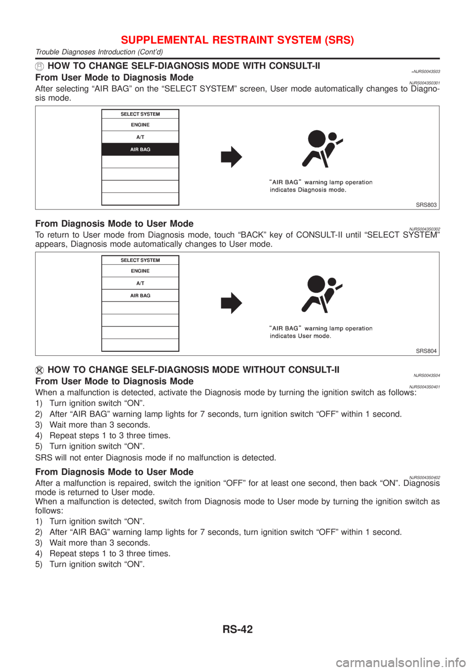
HOW TO CHANGE SELF-DIAGNOSIS MODE WITH CONSULT-II=NJRS0043S03From User Mode to Diagnosis ModeNJRS0043S0301After selecting ªAIR BAGº on the ªSELECT SYSTEMº screen, User mode automatically changes to Diagno-
sis mode.
SRS803
From Diagnosis Mode to User ModeNJRS0043S0302To return to User mode from Diagnosis mode, touch ªBACKº key of CONSULT-II until ªSELECT SYSTEMº
appears, Diagnosis mode automatically changes to User mode.
SRS804
HOW TO CHANGE SELF-DIAGNOSIS MODE WITHOUT CONSULT-IINJRS0043S04From User Mode to Diagnosis ModeNJRS0043S0401When a malfunction is detected, activate the Diagnosis mode by turning the ignition switch as follows:
1) Turn ignition switch ªONº.
2) After ªAIR BAGº warning lamp lights for 7 seconds, turn ignition switch ªOFFº within 1 second.
3) Wait more than 3 seconds.
4) Repeat steps 1 to 3 three times.
5) Turn ignition switch ªONº.
SRS will not enter Diagnosis mode if no malfunction is detected.
From Diagnosis Mode to User ModeNJRS0043S0402After a malfunction is repaired, switch the ignition ªOFFº for at least one second, then back ªONº. Diagnosis
mode is returned to User mode.
When a malfunction is detected, switch from Diagnosis mode to User mode by turning the ignition switch as
follows:
1) Turn ignition switch ªONº.
2) After ªAIR BAGº warning lamp lights for 7 seconds, turn ignition switch ªOFFº within 1 second.
3) Wait more than 3 seconds.
4) Repeat steps 1 to 3 three times.
5) Turn ignition switch ªONº.
SUPPLEMENTAL RESTRAINT SYSTEM (SRS)
Trouble Diagnoses Introduction (Cont'd)
RS-42
Page 1880 of 2493
SRS800
Trouble Diagnoses without CONSULT-II=NJRS0049DIAGNOSTIC PROCEDURE 6NJRS0049S01Inspecting SRS malfunctioning parts by using ªAIR BAGº
warning lamp Ð Diagnosis mode
NOTE:
SRS will not enter Diagnosis mode if no malfunction is
detected in User mode.
1. Turn ignition switch ªONº.
2. After ªAIR BAGº warning lamp lights for 7 seconds, turn igni-
tion switch ªOFFº within 1 second.
3. Wait more than 3 seconds.
4. Repeat steps 1 to 3 three times.
5. Turn ignition switch ªONº.
SRS is now in Diagnosis mode.
6. ªAIR BAGº warning lamp operates in Diagnosis mode as fol-
lows:
NOTE:
If SRS does not enter Diagnosis mode even though malfunction is
detected in User mode, check the battery voltage.
If the battery voltage is less than 9V, charge the battery. Then go
to DIAGNOSTIC PROCEDURE 7, page RS-65.
If the battery voltage is OK, replace the diagnosis sensor unit.
SUPPLEMENTAL RESTRAINT SYSTEM (SRS)
Trouble Diagnoses without CONSULT-II
RS-60