Page 1021 of 2395
LEFT BANKNBEC0711S02
MEC986C
DTC P1140 (RIGHT, -B1), P1145 (LEFT, -B2) INTAKE VALVE TIMING CONTROL
POSITION SENSOR (CIRCUIT)
Wiring Diagram (Cont'd)
EC-486
Page 1023 of 2395

3 DETECT MALFUNCTIONING PART
Check the following.
IHarness connectors M32, F23
IHarness connectors E1, M1
IHarness for open or short between ECM and intake valve timing control position sensor
IHarness for open or short between ECM relay and intake valve timing control position sensor
©Repair open circuit or short to ground or short to power in harness or connectors.
4 CHECK INTAKE VALVE TIMING CONTROL POSITION SENSOR GROUND CIRCUIT FOR OPEN AND
SHORT
1. Turn ignition switch ªOFFº.
2. Check harness connector continuity between intake valve timing control position sensor harness connector terminal 1
and engine ground. Refer to Wiring Diagram.
Continuity should exist.
3. Also check harness for short to power.
OK or NG
OK©GO TO 5.
NG©Repair open circuit or short to power in harness or connectors.
5 CHECK INTAKE VALVE TIMING CONTROL POSITION SENSOR INPUT SIGNAL CIRCUIT
1. Disconnect ECM harness connector.
2. Check harness connectors continuity between ECM terminal 79 (Right) or 89 (Left) and terminal 2. Refer to Wiring Dia-
gram.
Continuity should exist.
3. Also check harness for short to ground and short to power.
OK or NG
OK©GO TO 6.
NG©Repair open circuit or short to ground or short to power in harness or connectors.
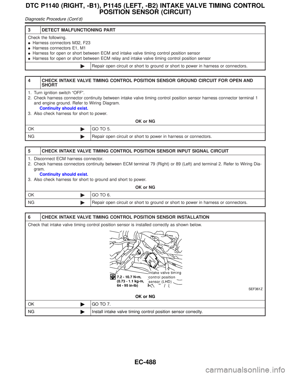
6 CHECK INTAKE VALVE TIMING CONTROL POSITION SENSOR INSTALLATION
Check that intake valve timing control position sensor is installed correctly as shown below.
SEF361Z
OK or NG
OK©GO TO 7.
NG©Install intake valve timing control position sensor correclty.
DTC P1140 (RIGHT, -B1), P1145 (LEFT, -B2) INTAKE VALVE TIMING CONTROL
POSITION SENSOR (CIRCUIT)
Diagnostic Procedure (Cont'd)
EC-488
Page 1030 of 2395
Wiring DiagramNBEC0538
MEC981C
GI
MA
EM
LC
FE
AT
TF
PD
AX
SU
BR
ST
RS
BT
HA
SC
EL
IDX
DTC P1165 SWIRL CONTROL VALVE CONTROL VACUUM CHECK SWITCH
Wiring Diagram
EC-495
Page 1031 of 2395
Diagnostic ProcedureNBEC0539
1 CHECK HOSES
1. Turn ignition switch ªOFFº.
2. Check hose for clogging or improper connection.
SEF109L
OK or NG
OK©GO TO 2.
NG©Repair or reconnect the hose.
2 CHECK SWIRL CONTROL VALVE CONTROL VACUUM CHECK SWITCH GROUND CIRCUIT FOR OPEN
AND SHORT
1. Disconnect swirl control valve control vacuum check switch harness connector.
SEF999Y
2. Check harness continuity between terminal 2 and ground. Refer to Wiring Diagram.
Continuity should exist.
3. Also check harness for short to power.
OK or NG
OK©GO TO 4.
NG©GO TO 3.
3 DETECT MALFUNCTIONING PART
Check the following.
IHarness connectors E1, M1 and M92, F27
IHarness for open between swirl control valve control vacuum check switch and engine ground
©Repair open circuit or short to power in harness connectors.
DTC P1165 SWIRL CONTROL VALVE CONTROL VACUUM CHECK SWITCH
Diagnostic Procedure
EC-496
Page 1032 of 2395

4 CHECK SWIRL CONTROL VALVE CONTROL VACUUM CHECK SWITCH INPUT SIGNAL CIRCUIT FOR
OPEN AND SHORT
1. Disconnect ECM harness connector.
2. Check harness continuity between ECM terminal 55 and swirl control valve control vacuum check switch terminal 1.
Refer to Wiring Diagram.
Continuity should exist.
3. Also check harness for short to ground and short to power.
OK or NG
OK©GO TO 5.
NG©Repair open circuit, short to ground or short to power in harness connectors.
5 CHECK SWIRL CONTROL VALVE CONTROL VACUUM CHECK SWITCH
1. Turn ignition switch ªOFFº.
2. Disconnect vacuum hose connected to swirl control valve control vacuum check switch.
3. Attach vacuum pump to swirl control valve control vacuum check switch.
4. Turn ignition switch ªONº.
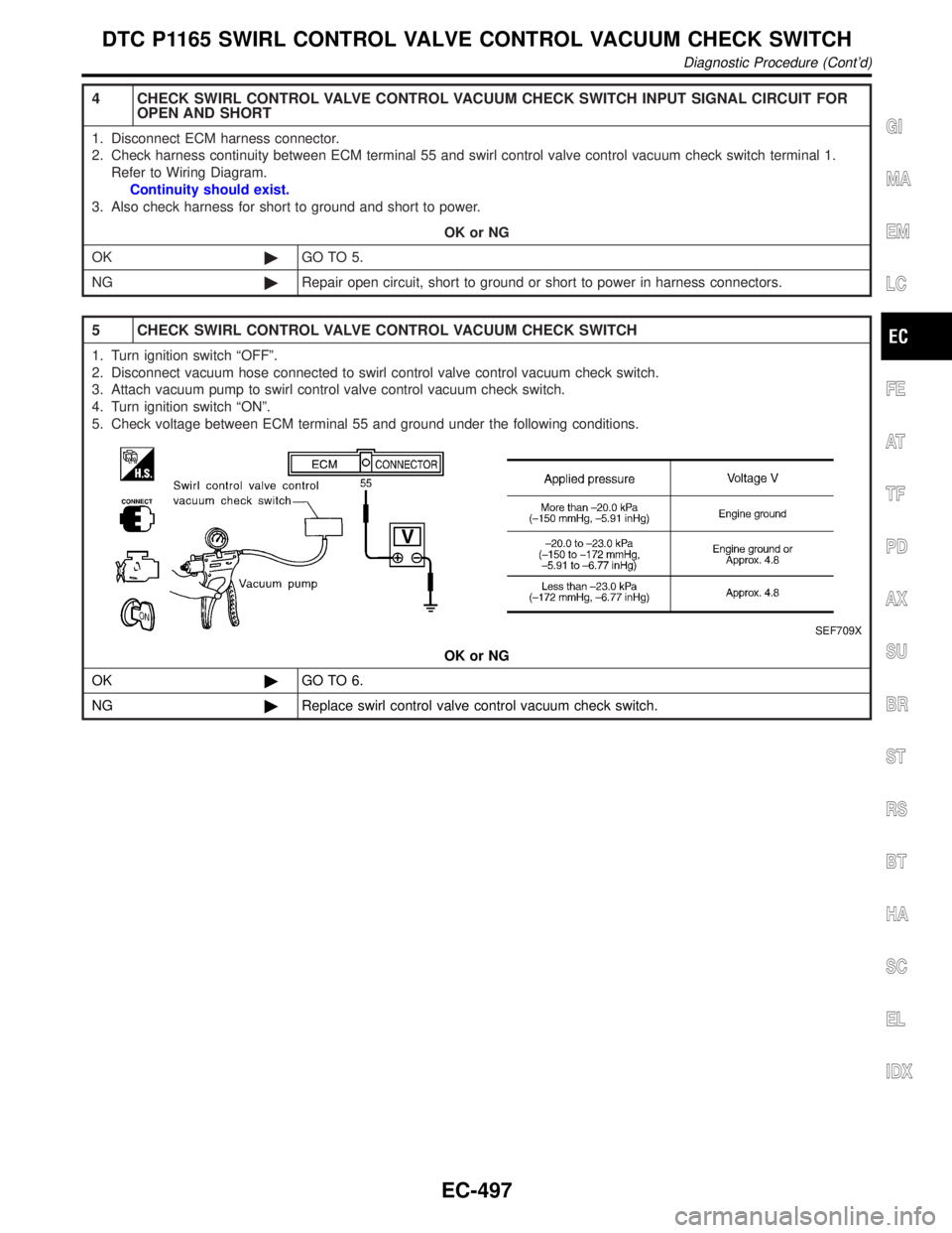
5. Check voltage between ECM terminal 55 and ground under the following conditions.
SEF709X
OK or NG
OK©GO TO 6.
NG©Replace swirl control valve control vacuum check switch.
GI
MA
EM
LC
FE
AT
TF
PD
AX
SU
BR
ST
RS
BT
HA
SC
EL
IDX
DTC P1165 SWIRL CONTROL VALVE CONTROL VACUUM CHECK SWITCH
Diagnostic Procedure (Cont'd)
EC-497
Page 1036 of 2395
Wiring DiagramNBEC0290
MEC969C
GI
MA
EM
LC
FE
AT
TF
PD
AX
SU
BR
ST
RS
BT
HA
SC
EL
IDX
DTC P1320 IGNITION SIGNAL
Wiring Diagram
EC-501
Page 1037 of 2395
MEC970C
DTC P1320 IGNITION SIGNAL
Wiring Diagram (Cont'd)
EC-502
Page 1038 of 2395
MEC971C
GI
MA
EM
LC
FE
AT
TF
PD
AX
SU
BR
ST
RS
BT
HA
SC
EL
IDX
DTC P1320 IGNITION SIGNAL
Wiring Diagram (Cont'd)
EC-503