Page 1124 of 2395

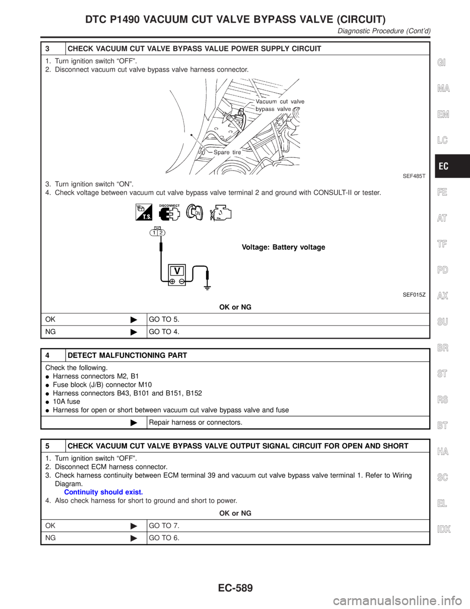
3 CHECK VACUUM CUT VALVE BYPASS VALUE POWER SUPPLY CIRCUIT
1. Turn ignition switch ªOFFº.
2. Disconnect vacuum cut valve bypass valve harness connector.
SEF485T
3. Turn ignition switch ªONº.
4. Check voltage between vacuum cut valve bypass valve terminal 2 and ground with CONSULT-II or tester.
SEF015Z
OK or NG
OK©GO TO 5.
NG©GO TO 4.
4 DETECT MALFUNCTIONING PART
Check the following.
IHarness connectors M2, B1
IFuse block (J/B) connector M10
IHarness connectors B43, B101 and B151, B152
I10A fuse
IHarness for open or short between vacuum cut valve bypass valve and fuse
©Repair harness or connectors.
5 CHECK VACUUM CUT VALVE BYPASS VALVE OUTPUT SIGNAL CIRCUIT FOR OPEN AND SHORT
1. Turn ignition switch ªOFFº.
2. Disconnect ECM harness connector.
3. Check harness continuity between ECM terminal 39 and vacuum cut valve bypass valve terminal 1. Refer to Wiring
Diagram.
Continuity should exist.
4. Also check harness for short to ground and short to power.
OK or NG
OK©GO TO 7.
NG©GO TO 6.
GI
MA
EM
LC
FE
AT
TF
PD
AX
SU
BR
ST
RS
BT
HA
SC
EL
IDX
DTC P1490 VACUUM CUT VALVE BYPASS VALVE (CIRCUIT)
Diagnostic Procedure (Cont'd)
EC-589
Page 1129 of 2395
Wiring DiagramNBEC0359
MEC972C
DTC P1491 VACUUM CUT VALVE BYPASS VALVE
Wiring Diagram
EC-594
Page 1142 of 2395
Wiring DiagramNBEC0373
MEC973C
GI
MA
EM
LC
FE
AT
TF
PD
AX
SU
BR
ST
RS
BT
HA
SC
EL
IDX
DTC P1706 PARK/NEUTRAL POSITION (PNP) SWITCH
Wiring Diagram
EC-607
Page 1143 of 2395

Diagnostic ProcedureNBEC0374
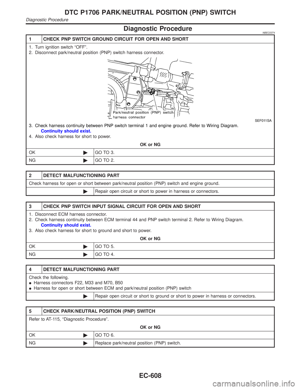
1 CHECK PNP SWITCH GROUND CIRCUIT FOR OPEN AND SHORT
1. Turn ignition switch ªOFFº.
2. Disconnect park/neutral position (PNP) switch harness connector.
SEF011SA
3. Check harness continuity between PNP switch terminal 1 and engine ground. Refer to Wiring Diagram.
Continuity should exist.
4. Also check harness for short to power.
OK or NG
OK©GO TO 3.
NG©GO TO 2.
2 DETECT MALFUNCTIONING PART
Check harness for open or short between park/neutral position (PNP) switch and engine ground.
©Repair open circuit or short to power in harness or connectors.
3 CHECK PNP SWITCH INPUT SIGNAL CIRCUIT FOR OPEN AND SHORT
1. Disconnect ECM harness connector.
2. Check harness continuity between ECM terminal 44 and PNP switch terminal 2. Refer to Wiring Diagram.
Continuity should exist.
3. Also check harness for short to ground and short to power.
OK or NG
OK©GO TO 5.
NG©GO TO 4.
4 DETECT MALFUNCTIONING PART
Check the following.
IHarness connectors F22, M33 and M70, B50
IHarness for open or short between ECM and park/neutral position (PNP) switch
©Repair open circuit or short to ground or short to power in harness or connectors.
5 CHECK PARK/NEUTRAL POSITION (PNP) SWITCH
Refer to AT-115, ªDiagnostic Procedureº.
OK or NG
OK©GO TO 6.
NG©Replace park/neutral position (PNP) switch.
DTC P1706 PARK/NEUTRAL POSITION (PNP) SWITCH
Diagnostic Procedure
EC-608
Page 1147 of 2395
Wiring DiagramNBEC0597
MEC990C
VARIABLE INDUCTION AIR CONTROL SYSTEM (VIAS)
Wiring Diagram
EC-612
Page 1149 of 2395

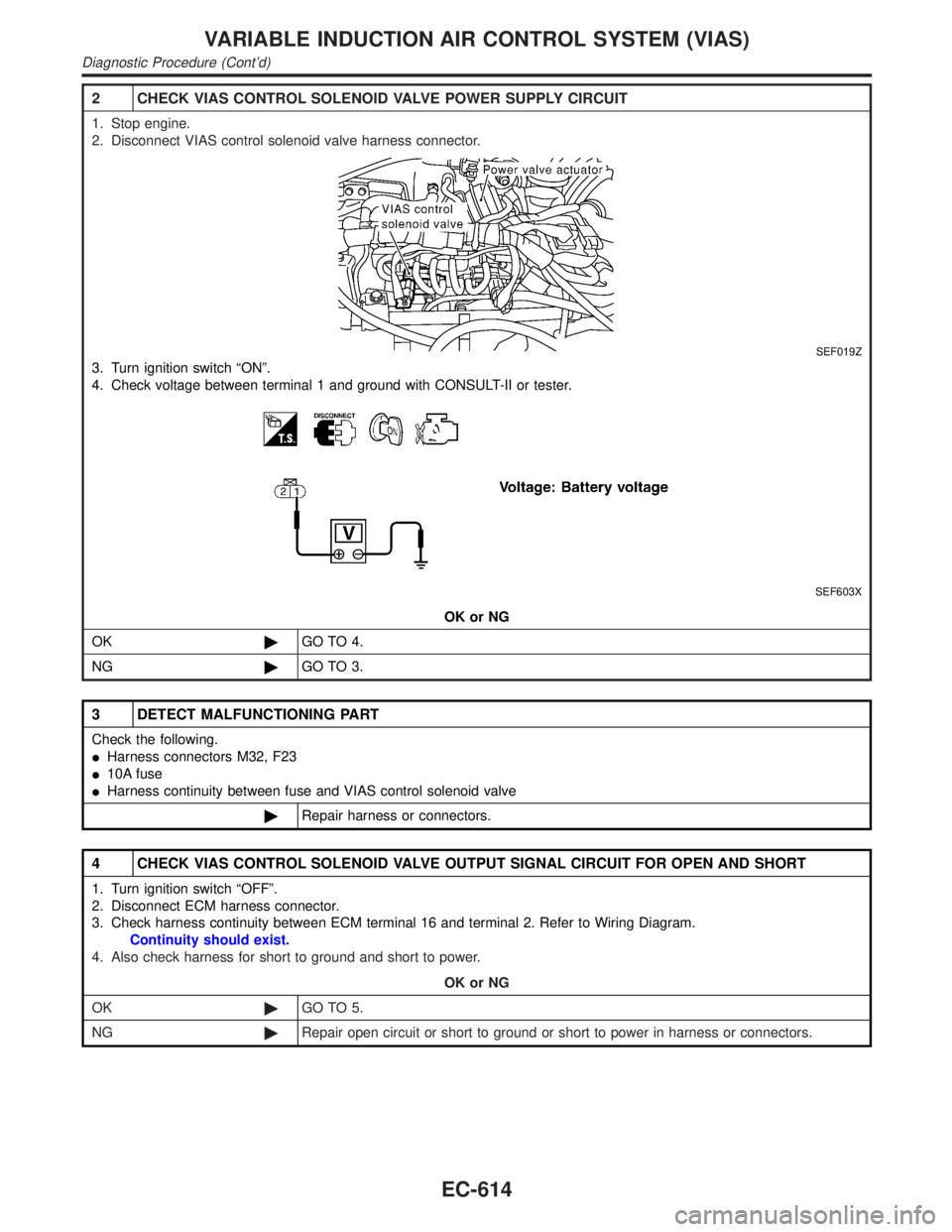
2 CHECK VIAS CONTROL SOLENOID VALVE POWER SUPPLY CIRCUIT
1. Stop engine.
2. Disconnect VIAS control solenoid valve harness connector.
SEF019Z
3. Turn ignition switch ªONº.
4. Check voltage between terminal 1 and ground with CONSULT-II or tester.
SEF603X
OK or NG
OK©GO TO 4.
NG©GO TO 3.
3 DETECT MALFUNCTIONING PART
Check the following.
IHarness connectors M32, F23
I10A fuse
IHarness continuity between fuse and VIAS control solenoid valve
©Repair harness or connectors.
4 CHECK VIAS CONTROL SOLENOID VALVE OUTPUT SIGNAL CIRCUIT FOR OPEN AND SHORT
1. Turn ignition switch ªOFFº.
2. Disconnect ECM harness connector.
3. Check harness continuity between ECM terminal 16 and terminal 2. Refer to Wiring Diagram.
Continuity should exist.
4. Also check harness for short to ground and short to power.
OK or NG
OK©GO TO 5.
NG©Repair open circuit or short to ground or short to power in harness or connectors.
VARIABLE INDUCTION AIR CONTROL SYSTEM (VIAS)
Diagnostic Procedure (Cont'd)
EC-614
Page 1152 of 2395
Wiring DiagramNBEC0386
MEC974C
GI
MA
EM
LC
FE
AT
TF
PD
AX
SU
BR
ST
RS
BT
HA
SC
EL
IDX
INJECTOR
Wiring Diagram
EC-617
Page 1154 of 2395
3 CHECK INJECTOR POWER SUPPLY CIRCUIT
1. Turn ignition switch ªOFFº.
SEF023Z
2. Turn ignition switch ªONº.
3. Check voltage between injector terminal 1 and ground with CONSULT-II or tester.
SEF364Z
OK or NG
OK©GO TO 5.
NG©GO TO 4.
4 DETECT MALFUNCTIONING PART
Check the following.
IHarness connectors M33, F22
IHarness connectors F5, F100
IFuse block (J/B) connector M10
I10A fuse
IHarness for open or short between injector and fuse
©Repair harness or connectors.
5 CHECK INJECTOR OUTPUT SIGNAL CIRCUIT FOR OPEN AND SHORT
1. Turn ignition switch ªOFFº.
2. Disconnect ECM harness connector.
3. Check harness continuity between injector terminal 2 and ECM terminals 103, 104, 107, 101, 105, 102. Refer to Wiring
Diagram.
Continuity should exist.
4. Also check harness for short to ground and short to power.
OK or NG
OK©GO TO 7.
NG©GO TO 6.
GI
MA
EM
LC
FE
AT
TF
PD
AX
SU
BR
ST
RS
BT
HA
SC
EL
IDX
INJECTOR
Diagnostic Procedure (Cont'd)
EC-619