Page 872 of 2395
Wiring DiagramNBEC0195
MEC959C
GI
MA
EM
LC
FE
AT
TF
PD
AX
SU
BR
ST
RS
BT
HA
SC
EL
IDX
DTC P0335 CRANKSHAFT POSITION SENSOR (CKPS) (POS)
Wiring Diagram
EC-337
Page 874 of 2395

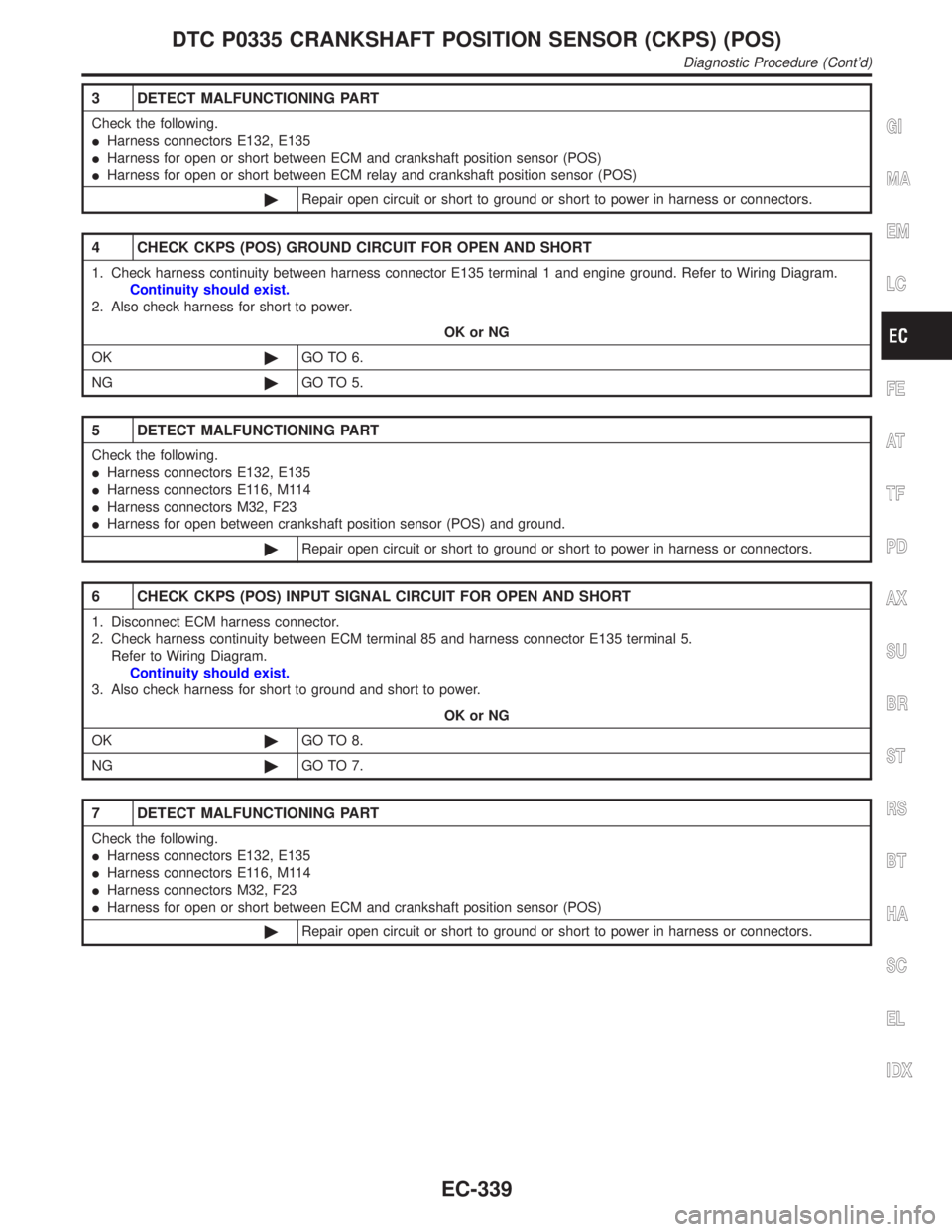
3 DETECT MALFUNCTIONING PART
Check the following.
IHarness connectors E132, E135
IHarness for open or short between ECM and crankshaft position sensor (POS)
IHarness for open or short between ECM relay and crankshaft position sensor (POS)
©Repair open circuit or short to ground or short to power in harness or connectors.
4 CHECK CKPS (POS) GROUND CIRCUIT FOR OPEN AND SHORT
1. Check harness continuity between harness connector E135 terminal 1 and engine ground. Refer to Wiring Diagram.
Continuity should exist.
2. Also check harness for short to power.
OK or NG
OK©GO TO 6.
NG©GO TO 5.
5 DETECT MALFUNCTIONING PART
Check the following.
IHarness connectors E132, E135
IHarness connectors E116, M114
IHarness connectors M32, F23
IHarness for open between crankshaft position sensor (POS) and ground.
©Repair open circuit or short to ground or short to power in harness or connectors.
6 CHECK CKPS (POS) INPUT SIGNAL CIRCUIT FOR OPEN AND SHORT
1. Disconnect ECM harness connector.
2. Check harness continuity between ECM terminal 85 and harness connector E135 terminal 5.
Refer to Wiring Diagram.
Continuity should exist.
3. Also check harness for short to ground and short to power.
OK or NG
OK©GO TO 8.
NG©GO TO 7.
7 DETECT MALFUNCTIONING PART
Check the following.
IHarness connectors E132, E135
IHarness connectors E116, M114
IHarness connectors M32, F23
IHarness for open or short between ECM and crankshaft position sensor (POS)
©Repair open circuit or short to ground or short to power in harness or connectors.
GI
MA
EM
LC
FE
AT
TF
PD
AX
SU
BR
ST
RS
BT
HA
SC
EL
IDX
DTC P0335 CRANKSHAFT POSITION SENSOR (CKPS) (POS)
Diagnostic Procedure (Cont'd)
EC-339
Page 876 of 2395

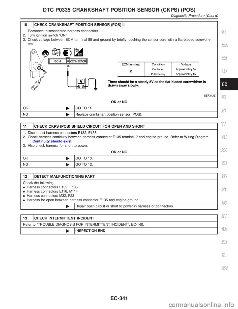
10 CHECK CRANKSHAFT POSITION SENSOR (POS)-II
1. Reconnect disconnected harness connectors.
2. Turn ignition switch ªONº.
3. Check voltage between ECM terminal 85 and ground by briefly touching the sensor core with a flat-bladed screwdriv-
ers.
SEF343Z
OK or NG
OK©GO TO 11.
NG©Replace crankshaft position sensor (POS).
11 CHECK CKPS (POS) SHIELD CIRCUIT FOR OPEN AND SHORT
1. Disconnect harness connectors E132, E135.
2. Check harness continuity between harness connector E135 terminal 2 and engine ground. Refer to Wiring Diagram.
Continuity should exist.
3. Also check harness for short to power.
OK or NG
OK©GO TO 13.
NG©GO TO 12.
12 DETECT MALFUNCTIONING PART
Check the following.
IHarness connectors E132, E135
IHarness connectors E116, M114
IHarness connectors M32, F23
IHarness for open between harness connector E135 and engine ground
©Repair open circuit or short to power in harness or connectors.
13 CHECK INTERMITTENT INCIDENT
Refer to ªTROUBLE DIAGNOSIS FOR INTERMITTENT INCIDENTº, EC-140.
©INSPECTION END
GI
MA
EM
LC
FE
AT
TF
PD
AX
SU
BR
ST
RS
BT
HA
SC
EL
IDX
DTC P0335 CRANKSHAFT POSITION SENSOR (CKPS) (POS)
Diagnostic Procedure (Cont'd)
EC-341
Page 879 of 2395
Wiring DiagramNBEC0201
MEC961C
DTC P0340 CAMSHAFT POSITION SENSOR (CMPS) (PHASE)
Wiring Diagram
EC-344
Page 880 of 2395
Diagnostic ProcedureNBEC0202
1 CHECK STARTING SYSTEM
Turn ignition switch to ªSTARTº position.
Does the engine turn over?
Does the starter motor operate?
YesorNo
Ye s©GO TO 2.
No©Check starting system. (Refer to SC-10, ªSTARTING SYSTEMº.)
2 RETIGHTEN GROUND SCREWS
1. Turn ignition switch ªOFFº.
2. Loosen and retighten engine ground screws.
SEF959Y
©GO TO 3.
3 CHECK CMPS (PHASE) INPUT SIGNAL CIRCUIT FOR OPEN AND SHORT
1. Turn ignition switch ªOFFº.
2. Disconnect ECM harness connector and CMPS (PHASE) harness connector.
SEF982Y
3. Check harness continuity between CMPS (PHASE) terminal 2 and ECM terminals 66, 76. Refer to Wiring Diagram.
Continuity should exist.
4. Also check harness for short to ground and short to power.
OK or NG
OK©GO TO 4.
NG©Repair open circuit or short to ground or short to power in harness or connectors.
GI
MA
EM
LC
FE
AT
TF
PD
AX
SU
BR
ST
RS
BT
HA
SC
EL
IDX
DTC P0340 CAMSHAFT POSITION SENSOR (CMPS) (PHASE)
Diagnostic Procedure
EC-345
Page 885 of 2395
4 CHECK IGNITION TIMING
Check the following items. Refer to ªBasic Inspectionº, EC-101.
MTBL0655
OK or NG
OK©GO TO 5.
NG©Follow the ªBasic Inspectionº.
5 CHECK INJECTORS
1. Refer to WIRING DIAGRAM for Injectors, EC-617.
2. Stop engine and then turn ignition switch ªONº.
3. Check voltage between ECM terminals 101, 102, 103, 104, 105, 107 and ground with CONSULT-II or tester.
SEF331X
OK or NG
OK©GO TO 6.
NG©Perform ªDiagnostic Procedureº, ªINJECTORº, EC-618.
DTC P0420 (RIGHT BANK, -B1), P0430 (LEFT BANK, -B2) THREE WAY
CATALYST FUNCTION
Diagnostic Procedure (Cont'd)
EC-350
Page 905 of 2395
Wiring DiagramNBEC0226
MEC962C
DTC P0443 EVAP CANISTER PURGE VOLUME CONTROL SOLENOID VALVE
(CIRCUIT)
Wiring Diagram
EC-370
Page 907 of 2395
3 CHECK EVAP CANISTER PURGE VOLUME CONTROL SOLENOID VALVE OUTPUT SIGNAL CIRCUIT
FOR OPEN AND SHORT
1. Turn ignition switch ªOFFº.
2. Disconnect ECM harness connector.
3. Check harness continuity between ECM terminal 1 and EVAP canister purge volume control solenoid valve terminal 2.
Refer to Wiring Diagram.
Continuity should exist.
4. Also check harness for short to ground and short to power.
OK or NG
OK (With CONSULT-II)©GO TO 4.
OK (Without CONSULT-
II)©GO TO 5.
NG©Repair open circuit or short to ground and short to power in harness or connetors.
4 CHECK EVAP CANISTER PURGE VOLUME CONTROL SOLENOID VALVE OPERATION
With CONSULT-II
1. Start engine.
2. Perform ªPURG VOL CONT/Vº in ªACTIVE TESTº mode with CONSULT-II. Check that engine speed varies according
to the valve opening.
SEF985Y
OK or NG
OK©GO TO 6.
NG©GO TO 5.
DTC P0443 EVAP CANISTER PURGE VOLUME CONTROL SOLENOID VALVE
(CIRCUIT)
Diagnostic Procedure (Cont'd)
EC-372