2001 INFINITI QX4 Idle air
[x] Cancel search: Idle airPage 965 of 2395

10 CHECK IACV-AAC VALVE-II
1. Reconnect IACV-AAC valve harness connector and ECM harness connector.
2. Turn ignition switch ªONº and ªOFFº, and ensure the IACV-AAC valve makes operating sound according to the ignition
switch position.
SEF997Y
OK or NG
OK©GO TO 12.
NG©GO TO 11.
11 REPLACE IACV-AAC VALVE
1. Replace IACV-AAC valve assembly.
2. Perform ªIdle Air Volume Learningº, EC-57.
Is the result CMPLT or INCMP?
CMPLT or INCMP
CMPLT©INSPECTION END
INCMP©Follow the construction of ªIdle Air Volume Learningº.
12 CHECK TARGET IDLE SPEED
1. Turn ignition switch ªOFFº.
2. Reconnect all harness connectors and vacuum hoses.
3. Start engine and warm it up to normal operating temperature.
4. Also warm up transmission to normal operating temperature.
IFor A/T models with CONSULT-II, drive vehicle until ªFLUID TEMP SEº in ªDATA MONITORº mode of ªA/Tº system indi-
cates less than 0.9V.
IFor A/T models without CONSULT-II, drive vehicle for 10 minutes.
5. Stop vehicle with engine running.
6. Check target idle speed.
A/T: 750±50 rpm (in ªPº or ªNº position)
OK or NG
OK©GO TO 13.
NG©Perform ªIdle Air Volume Learningº, EC-57.
13 CHECK INTERMITTENT INCIDENT
Refer to ªTROUBLE DIAGNOSIS FOR INTERMITTENT INCIDENTº, EC-140.
©INSPECTION END
DTC P0505 IDLE AIR CONTROL VALVE (IACV) Ð AUXILIARY AIR CONTROL
(AAC) VALVE
Diagnostic Procedure (Cont'd)
EC-430
Page 975 of 2395

System DescriptionNBEC0264This circuit line (LAN) is used to control the smooth shifting up and down of A/T during the hard acceleration/
deceleration.
Pulse signals are exchanged between ECM and TCM (Transmission Control Module).
Be sure to erase the malfunction information such as DTC not only in TCM but also ECM after the A/T
related repair.
ECM Terminals and Reference ValueNBEC0672Specification data are reference values and are measured between each terminal and ground.
CAUTION:
Do not use ECM ground terminals when measuring input/output voltage. Doing so may result in dam-
age to the ECM's transistor. Use a ground other than ECM terminals, such as the ground.
TERMI-
NAL
NO.WIRE
COLORITEM CONDITION DATA (DC Voltage)
114 G/RCommunication line
(LAN)[Engine is running]
IIdle speedApproximately 2V
On Board Diagnosis LogicNBEC0266Malfunction is detected when ECM receives incorrect voltage from
TCM (Transmission Control Module) continuously.
Possible CauseNBEC0517IHarness or connectors
[The communication line circuit between ECM and TCM
(Transmission Control Module) is open or shorted.]
ITCM
IDead (Weak) battery
SEF058Y
DTC Confirmation ProcedureNBEC0267NOTE:
If ªDTC Confirmation Procedureº has been previously conducted,
always turn ignition switch ªOFFº and wait at least 10 seconds
before conducting the next test.
TESTING CONDITION:
Before performing the following procedure, confirm that bat-
tery voltage is more than 10.5V at idle.
WITH CONSULT-IINBEC0267S011) Turn ignition switch ªONº.
DTC P0600 A/T COMMUNICATION LINE
System Description
EC-440
Page 980 of 2395

Diagnostic ProcedureNBEC0274
1 INSPECTION START
With CONSULT-II
1. Turn ignition switch ªONº.
2. Select ªSELF DIAG RESULTSº mode with CONSULT-II.
3. Touch ªERASEº.
4.Perform ªDTC Confirmation Procedureº.
See EC-444.
5. Is the 1st trip DTC P0605 displayed again?
With GST
1. Turn ignition switch ªONº.
2. Select MODE 4 with GST.
3. Touch ªERASEº.
4.Perform ªDTC Confirmation Procedureº.
See EC-444.
5. Is the 1st trip DTC P0605 displayed again?
YesorNo
Ye s©GO TO 2.
No©INSPECTION END
2 REPLACE ECM
1. Replace ECM.
2. Perform initialization of NVIS (NATS) system and registration of all NVIS (NATS) ignition key IDs. Refer to ªNVIS (NIS-
SAN VEHICLE IMMOBILIZER SYSTEM Ð NATS)º, EC-74.
3. Perform ªIdle Air Volume Learningº, EC-57,
Is the result CMPLT or INCMP?
CMPLT or INCMP
CMPLT©INSPECTION END
INCMP©Follow the construction of ªIdle Air Volume Learningº.
GI
MA
EM
LC
FE
AT
TF
PD
AX
SU
BR
ST
RS
BT
HA
SC
EL
IDX
DTC P0605 ECM
Diagnostic Procedure
EC-445
Page 993 of 2395

DescriptionNBEC0523If DTC P1130 is displayed with P1165, first perform trouble diag-
nosis for DTC P1165, EC-493.
SYSTEM DESCRIPTIONNBEC0523S01
Sensor Input Signal to ECMECM func-
tionActuator
Throttle position sensor Throttle position
Swirl control
valve con-
trolSwirl control valve control sole-
noid valve
"Vacuum signal
Swirl control valve actuator
"
Swirl control valve Ignition switch Start signal
Crankshaft position sensor (POS) Engine speed (POS signal)
Crankshaft position sensor (REF) Engine speed (REF signal)
Mass air flow sensor Amount of intake air
Engine coolant temperature sensor Engine coolant temperature
This system has a swirl control valve in the intake passage of each
cylinder.
While idling and during low engine speed operation, the swirl con-
trol valve closes. Thus the velocity of the air in the intake passage
increases, promoting the vaporization of the fuel and producing a
swirl in the combustion chamber.
Because of this operation, this system tends to increase the burn-
ing speed of the gas mixture, improve fuel consumption, and
increase the stability in running conditions.
Also, except when idling and during low engine speed operation,
this system opens the swirl control valve. In this condition, this
system tends to increase power by improving intake efficiency via
reduction of intake flow resistance, intake flow.
The solenoid valve controls swirl control valve's shut/open condi-
tion. This solenoid valve is operated by the ECM.
Throttle position
sensor (Idle posi-
tion)Engine speedSwirl control valve
control solenoid
valveSwirl control valve
ON Below 3,200 rpm ON Closed
OFFLess than 3,200
rpmON Closed
More than 3,600
rpmOFF Open
When engine coolant temperature is below 10ÉC (50ÉF) and above 55ÉC (131ÉF),
swirl control valve is kept open regardless of above condition.
SEF446Z
DTC P1130 SWIRL CONTROL VALVE CONTROL SOLENOID VALVE
Description
EC-458
Page 1001 of 2395

PROCEDURE BNBEC0530S02
1 CHECK INTAKE SYSTEM
1. Start engine and let it idle.
2. Check intake air system for air leaks.
OK or NG
OK (With CONSULT-II)©GO TO 2.
OK (Without CONSULT-
II)©GO TO 3.
NG©Repair intake system.
2 CHECK SWIRL CONTROL VALVE CONTROL SOLENOID VALVE CIRCUIT
With CONSULT-II
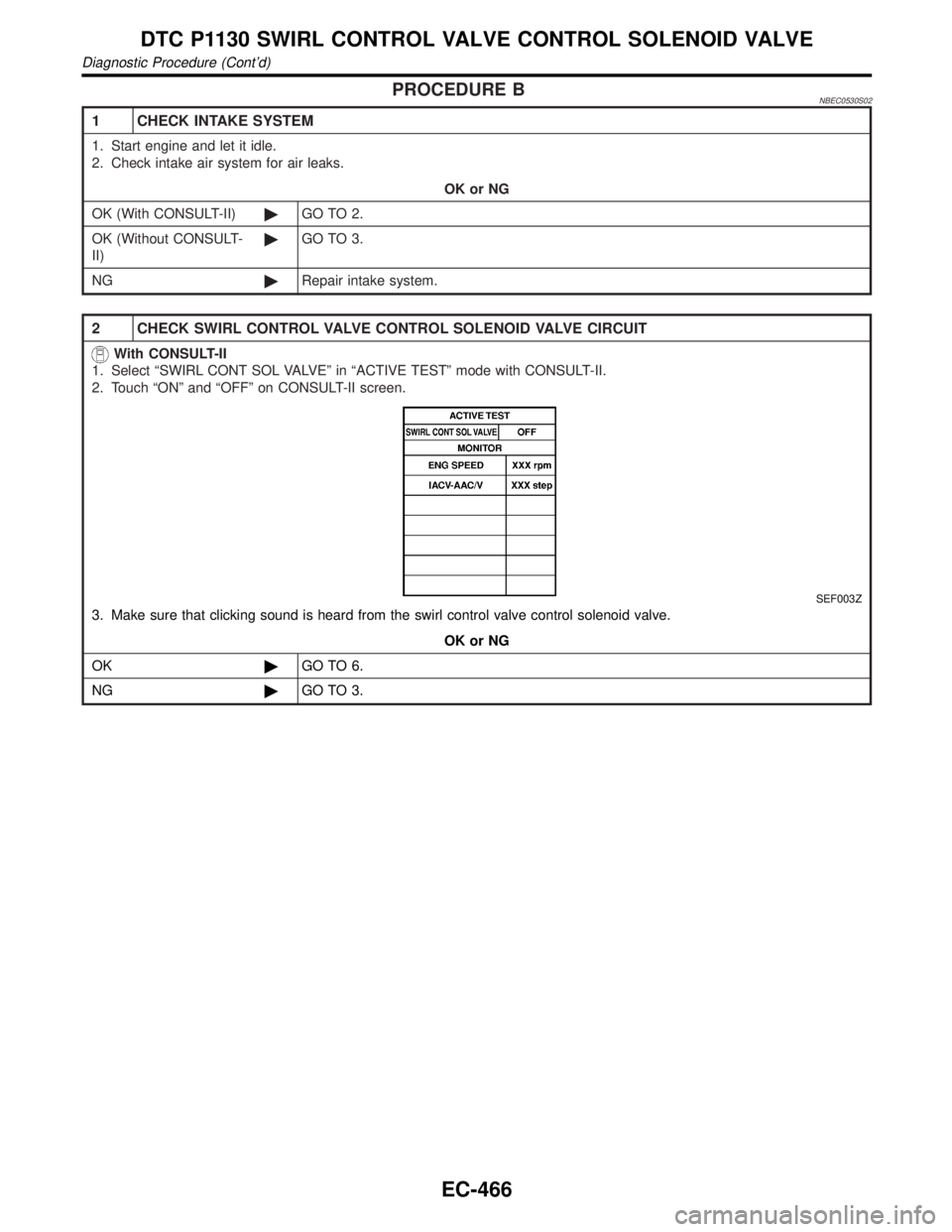
1. Select ªSWIRL CONT SOL VALVEº in ªACTIVE TESTº mode with CONSULT-II.
2. Touch ªONº and ªOFFº on CONSULT-II screen.
SEF003Z
3. Make sure that clicking sound is heard from the swirl control valve control solenoid valve.
OK or NG
OK©GO TO 6.
NG©GO TO 3.
DTC P1130 SWIRL CONTROL VALVE CONTROL SOLENOID VALVE
Diagnostic Procedure (Cont'd)
EC-466
Page 1062 of 2395

IEVAP purge line rubber tube bent.
IBlocked or bent rubber tube to EVAP control system pressure
sensor
ILoose or disconnected rubber tube
IEVAP canister vent control valve and the circuit
IEVAP canister purge volume control solenoid valve
IAbsolute pressure sensor
IFuel tank temperature sensor
IO-ring of EVAP canister vent control valve is missing or dam-
aged.
IWater separator
IEVAP canister is saturated with water.
IFuel level sensor and the circuit
IEVAP control system pressure sensor
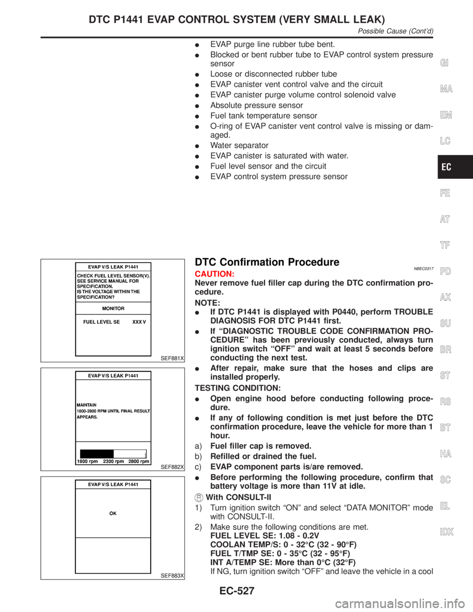
SEF881X
SEF882X
SEF883X
DTC Confirmation ProcedureNBEC0317CAUTION:
Never remove fuel filler cap during the DTC confirmation pro-
cedure.
NOTE:
IIf DTC P1441 is displayed with P0440, perform TROUBLE
DIAGNOSIS FOR DTC P1441 first.
IIf ªDIAGNOSTIC TROUBLE CODE CONFIRMATION PRO-
CEDUREº has been previously conducted, always turn
ignition switch ªOFFº and wait at least 5 seconds before
conducting the next test.
IAfter repair, make sure that the hoses and clips are
installed properly.
TESTING CONDITION:
IOpen engine hood before conducting following proce-
dure.
IIf any of following condition is met just before the DTC
confirmation procedure, leave the vehicle for more than 1
hour.
a)Fuel filler cap is removed.
b)Refilled or drained the fuel.
c)EVAP component parts is/are removed.
IBefore performing the following procedure, confirm that
battery voltage is more than 11V at idle.
With CONSULT-II
1) Turn ignition switch ªONº and select ªDATA MONITORº mode
with CONSULT-II.
2) Make sure the following conditions are met.
FUEL LEVEL SE: 1.08 - 0.2V
COOLAN TEMP/S: 0 - 32ÉC (32 - 90ÉF)
FUEL T/TMP SE: 0 - 35ÉC (32 - 95ÉF)
INT A/TEMP SE: More than 0ÉC (32ÉF)
If NG, turn ignition switch ªOFFº and leave the vehicle in a cool
GI
MA
EM
LC
FE
AT
TF
PD
AX
SU
BR
ST
RS
BT
HA
SC
EL
IDX
DTC P1441 EVAP CONTROL SYSTEM (VERY SMALL LEAK)
Possible Cause (Cont'd)
EC-527
Page 1070 of 2395

11 CHECK EVAP CANISTER
Weigh the EVAP canister with the EVAP canister vent control valve attached.
The weight should be less than 1.8 kg (4.0 lb).
OK or NG
OK (With CONSULT-II)©GO TO 13.
OK (Without CONSULT-
II)©GO TO 14.
NG©GO TO 12.
12 DETECT MALFUNCTIONING PART
Check the following.
IEVAP canister for damage
IEVAP hose between EVAP canister and water separator for clogging or poor connection
©Repair hose or replace EVAP canister.
13 CHECK EVAP CANISTER PURGE VOLUME CONTROL SOLENOID VALVE OPERATION
With CONSULT-II
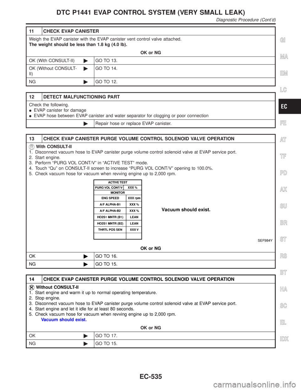
1. Disconnect vacuum hose to EVAP canister purge volume control solenoid valve at EVAP service port.
2. Start engine.
3. Perform ªPURG VOL CONT/Vº in ªACTIVE TESTº mode.
4. Touch ªQuº on CONSULT-II screen to increase ªPURG VOL CONT/Vº opening to 100.0%.
5. Check vacuum hose for vacuum when revving engine up to 2,000 rpm.
SEF984Y
OK or NG
OK©GO TO 16.
NG©GO TO 15.
14 CHECK EVAP CANISTER PURGE VOLUME CONTROL SOLENOID VALVE OPERATION
Without CONSULT-II
1. Start engine and warm it up to normal operating temperature.
2. Stop engine.
3. Disconnect vacuum hose to EVAP canister purge volume control solenoid valve at EVAP service port.
4. Start engine and let it idle for at least 80 seconds.
5. Check vacuum hose for vacuum when revving engine up to 2,000 rpm.
Vacuum should exist.
OK or NG
OK©GO TO 17.
NG©GO TO 15.
GI
MA
EM
LC
FE
AT
TF
PD
AX
SU
BR
ST
RS
BT
HA
SC
EL
IDX
DTC P1441 EVAP CONTROL SYSTEM (VERY SMALL LEAK)
Diagnostic Procedure (Cont'd)
EC-535
Page 1076 of 2395

DescriptionNBEC0319SYSTEM DESCRIPTIONNBEC0319S01
Sensor Input Signal to ECMECM
functionActuator
Crankshaft position sensor (POS) Engine speed (POS signal)
EVAP can-
ister purge
flow controlEVAP canister purge volume
control solenoid valve Crankshaft position sensor (REF) Engine speed (REF signal)
Mass air flow sensor Amount of intake air
Engine coolant temperature sensor Engine coolant temperature
Ignition switch Start signal
Throttle position sensor Throttle position
Throttle position switch Closed throttle position
Heated oxygen sensorsDensity of oxygen in exhaust gas
(Mixture ratio feedback signal)
Fuel tank temperature sensor Fuel temperature in fuel tank
Vehicle speed sensor Vehicle speed
This system controls flow rate of fuel vapor from the EVAP canis-
ter. The opening of the vapor by-pass passage in the EVAP canis-
ter purge volume control solenoid valve changes to control the flow
rate. The EVAP canister purge volume control solenoid valve
repeats ON/OFF operation according to the signal sent from the
ECM. The opening of the valve varies for optimum engine control.
The optimum value stored in the ECM is determined by consider-
ing various engine conditions. When the engine is operating, the
flow rate of fuel vapor from the EVAP canister is regulated as the
air flow changes.
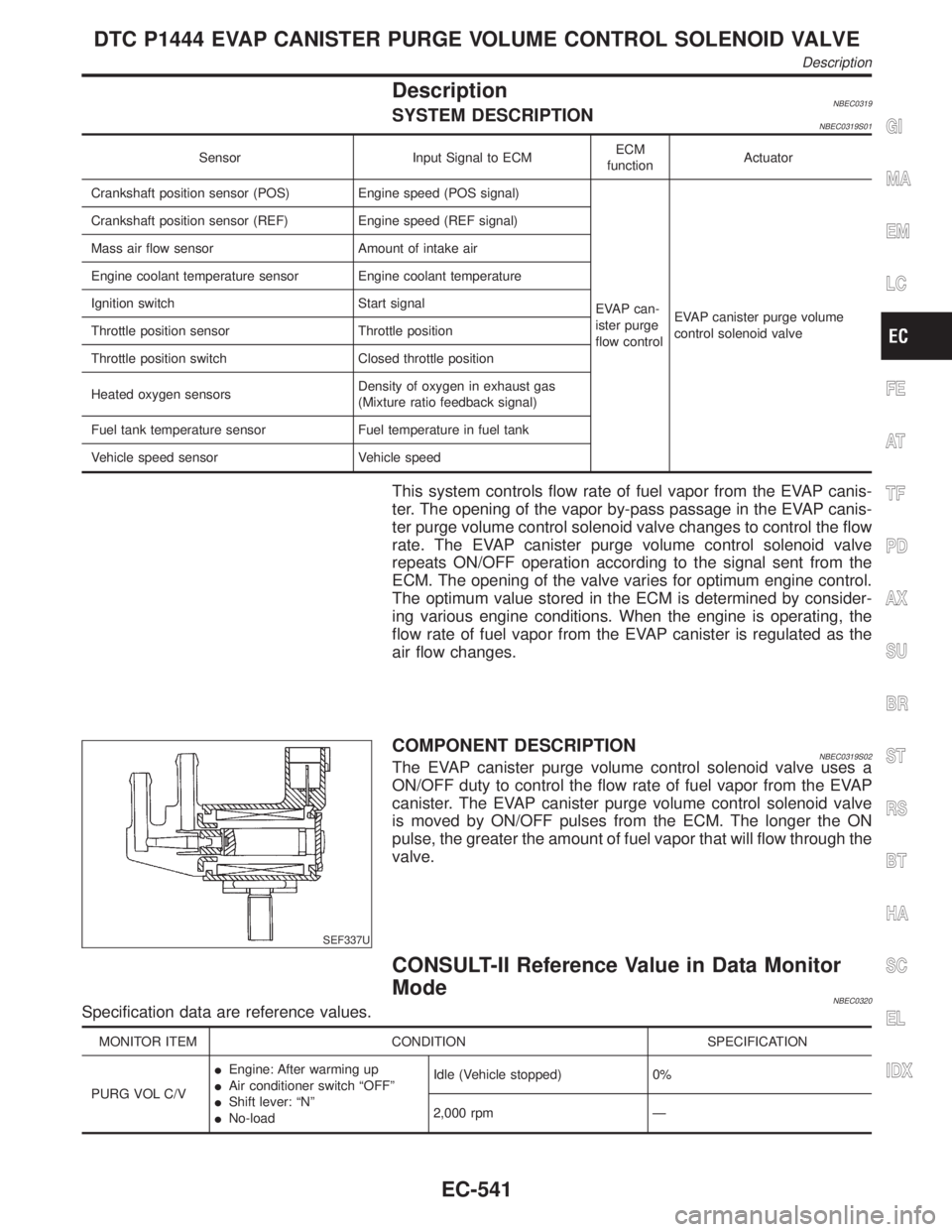
SEF337U
COMPONENT DESCRIPTIONNBEC0319S02The EVAP canister purge volume control solenoid valve uses a
ON/OFF duty to control the flow rate of fuel vapor from the EVAP
canister. The EVAP canister purge volume control solenoid valve
is moved by ON/OFF pulses from the ECM. The longer the ON
pulse, the greater the amount of fuel vapor that will flow through the
valve.
CONSULT-II Reference Value in Data Monitor
Mode
NBEC0320Specification data are reference values.
MONITOR ITEM CONDITION SPECIFICATION
PURG VOL C/VIEngine: After warming up
IAir conditioner switch ªOFFº
IShift lever: ªNº
INo-loadIdle (Vehicle stopped) 0%
2,000 rpm Ð
GI
MA
EM
LC
FE
AT
TF
PD
AX
SU
BR
ST
RS
BT
HA
SC
EL
IDX
DTC P1444 EVAP CANISTER PURGE VOLUME CONTROL SOLENOID VALVE
Description
EC-541