Page 2236 of 2395

TRANSFER
SECTION
TF
CONTENTS
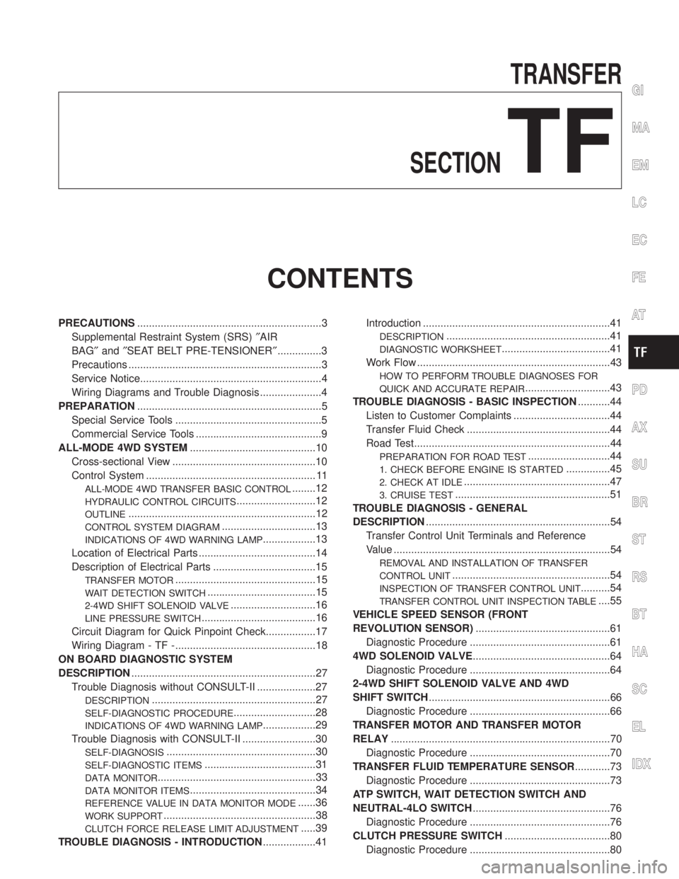
PRECAUTIONS...............................................................3
Supplemental Restraint System (SRS)²AIR
BAG²and²SEAT BELT PRE-TENSIONER²...............3
Precautions ..................................................................3
Service Notice..............................................................4
Wiring Diagrams and Trouble Diagnosis .....................4
PREPARATION...............................................................5
Special Service Tools ..................................................5
Commercial Service Tools ...........................................9
ALL-MODE 4WD SYSTEM...........................................10
Cross-sectional View .................................................10
Control System .......................................................... 11
ALL-MODE 4WD TRANSFER BASIC CONTROL........12
HYDRAULIC CONTROL CIRCUITS...........................12
OUTLINE................................................................12
CONTROL SYSTEM DIAGRAM................................13
INDICATIONS OF 4WD WARNING LAMP..................13
Location of Electrical Parts ........................................14
Description of Electrical Parts ...................................15
TRANSFER MOTOR................................................15
WAIT DETECTION SWITCH.....................................15
2-4WD SHIFT SOLENOID VALVE.............................16
LINE PRESSURE SWITCH.......................................16
Circuit Diagram for Quick Pinpoint Check.................17
Wiring Diagram - TF -................................................18
ON BOARD DIAGNOSTIC SYSTEM
DESCRIPTION...............................................................27
Trouble Diagnosis without CONSULT-II ....................27
DESCRIPTION........................................................27
SELF-DIAGNOSTIC PROCEDURE............................28
INDICATIONS OF 4WD WARNING LAMP..................29
Trouble Diagnosis with CONSULT-II .........................30
SELF-DIAGNOSIS...................................................30
SELF-DIAGNOSTIC ITEMS......................................31
DATA MONITOR......................................................33
DATA MONITOR ITEMS...........................................34
REFERENCE VALUE IN DATA MONITOR MODE......36
WORK SUPPORT....................................................38
CLUTCH FORCE RELEASE LIMIT ADJUSTMENT.....39
TROUBLE DIAGNOSIS - INTRODUCTION..................41Introduction ................................................................41
DESCRIPTION........................................................41
DIAGNOSTIC WORKSHEET.....................................41
Work Flow ..................................................................43
HOW TO PERFORM TROUBLE DIAGNOSES FOR
QUICK AND ACCURATE REPAIR
.............................43
TROUBLE DIAGNOSIS - BASIC INSPECTION...........44
Listen to Customer Complaints .................................44
Transfer Fluid Check .................................................44
Road Test...................................................................44
PREPARATION FOR ROAD TEST............................44
1. CHECK BEFORE ENGINE IS STARTED...............45
2. CHECK AT IDLE..................................................47
3. CRUISE TEST.....................................................51
TROUBLE DIAGNOSIS - GENERAL
DESCRIPTION...............................................................54
Transfer Control Unit Terminals and Reference
Value ..........................................................................54
REMOVAL AND INSTALLATION OF TRANSFER
CONTROL UNIT
......................................................54
INSPECTION OF TRANSFER CONTROL UNIT..........54
TRANSFER CONTROL UNIT INSPECTION TABLE....55
VEHICLE SPEED SENSOR (FRONT
REVOLUTION SENSOR)..............................................61
Diagnostic Procedure ................................................61
4WD SOLENOID VALVE...............................................64
Diagnostic Procedure ................................................64
2-4WD SHIFT SOLENOID VALVE AND 4WD
SHIFT SWITCH..............................................................66
Diagnostic Procedure ................................................66
TRANSFER MOTOR AND TRANSFER MOTOR
RELAY...........................................................................70
Diagnostic Procedure ................................................70
TRANSFER FLUID TEMPERATURE SENSOR............73
Diagnostic Procedure ................................................73
ATP SWITCH, WAIT DETECTION SWITCH AND
NEUTRAL-4LO SWITCH...............................................76
Diagnostic Procedure ................................................76
CLUTCH PRESSURE SWITCH....................................80
Diagnostic Procedure ................................................80
GI
MA
EM
LC
EC
FE
AT
PD
AX
SU
BR
ST
RS
BT
HA
SC
EL
IDX
Page 2277 of 2395
Diagnostic WorksheetNBTF0013S0202
1.lListen to customer complaints.TF-44
2.lCheck transfer fluid.TF-44
lLeakage
lFluid condition
lFluid level
3.lRoad testingTF-44
l1. Check before engine is started.
l2. Check at idle.
l3. Cruise test
4.lPerform self-diagnosis NG items (with CONSULT-II and without CONSULT-II). TF-30, TF-27
5.lCheck component. Repair or replace the damaged parts. TF-111
6.lPerform final check. Perform road test (1 through 3). TF-44
TROUBLE DIAGNOSIS Ð INTRODUCTION
Introduction (Cont'd)
TF-42
Page 2279 of 2395

Listen to Customer ComplaintsNBTF0015IEach customer feels differently about a problem. It is important
to fully understand the symptoms or conditions for a customer
complaint.
IListen to the customer about how and when the malfunction
occurs, and make good use of it when performing the road test.
Transfer Fluid CheckNBTF0016ICheck fluid for leaks and fluid level. Refer to MA-22, ªCheck-
ing All-mode 4WD Transfer Fluidº.
SMT089D
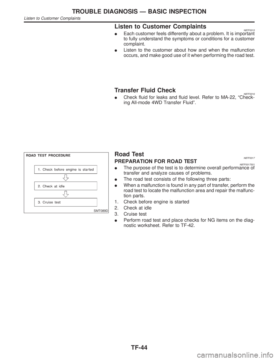
Road TestNBTF0017PREPARATION FOR ROAD TESTNBTF0017S01IThe purpose of the test is to determine overall performance of
transfer and analyze causes of problems.
IThe road test consists of the following three parts:
IWhen a malfunction is found in any part of transfer, perform the
road test to locate the malfunction area and repair the malfunc-
tion parts.
1. Check before engine is started
2. Check at idle
3. Cruise test
IPerform road test and place checks for NG items on the diag-
nostic worksheet. Refer to TF-42.
TROUBLE DIAGNOSIS Ð BASIC INSPECTION
Listen to Customer Complaints
TF-44
Page 2305 of 2395

Diagnostic ProcedureNBTF0022
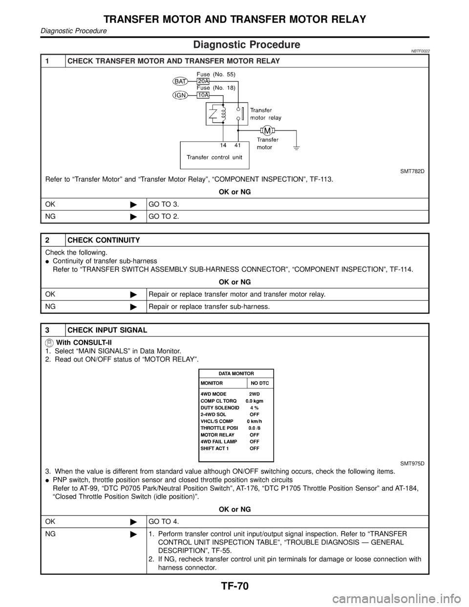
1 CHECK TRANSFER MOTOR AND TRANSFER MOTOR RELAY
SMT782D
Refer to ªTransfer Motorº and ªTransfer Motor Relayº, ªCOMPONENT INSPECTIONº, TF-113.
OK or NG
OK©GO TO 3.
NG©GO TO 2.
2 CHECK CONTINUITY
Check the following.
IContinuity of transfer sub-harness
Refer to ªTRANSFER SWITCH ASSEMBLY SUB-HARNESS CONNECTORº, ªCOMPONENT INSPECTIONº, TF-114.
OK or NG
OK©Repair or replace transfer motor and transfer motor relay.
NG©Repair or replace transfer sub-harness.
3 CHECK INPUT SIGNAL
With CONSULT-II
1. Select ªMAIN SIGNALSº in Data Monitor.
2. Read out ON/OFF status of ªMOTOR RELAYº.
SMT975D
3. When the value is different from standard value although ON/OFF switching occurs, check the following items.
IPNP switch, throttle position sensor and closed throttle position switch circuits
Refer to AT-99, ªDTC P0705 Park/Neutral Position Switchº, AT-176, ªDTC P1705 Throttle Position Sensorº and AT-184,
ªClosed Throttle Position Switch (idle position)º.
OK or NG
OK©GO TO 4.
NG©1. Perform transfer control unit input/output signal inspection. Refer to ªTRANSFER
CONTROL UNIT INSPECTION TABLEº, ªTROUBLE DIAGNOSIS Ð GENERAL
DESCRIPTIONº, TF-55.
2. If NG, recheck transfer control unit pin terminals for damage or loose connection with
harness connector.
TRANSFER MOTOR AND TRANSFER MOTOR RELAY
Diagnostic Procedure
TF-70