Page 1098 of 2395

SEF355X
Overall Function CheckNBEC0336Use this procedure to check the overall monitoring function of the
EVAP control system purge flow monitoring. During this check, a
1st trip DTC might not be confirmed.
WITH GSTNBEC0336S011) Lift up drive wheels.
2) Start engine (TCS switch ªOFFº) and warm it up to normal
operating temperature.
3) Turn ignition switch ªOFFº, wait at least 10 seconds.
4) Start engine and wait at least 70 seconds.
5) Set voltmeter probes to ECM terminals 84 (EVAP control sys-
tem pressure sensor signal) and ground.
6) Check EVAP control system pressure sensor value at idle
speed and note it.
7) Establish and maintain the following conditions for at least 1
minute.
Air conditioner switch ON
Steering wheel Fully turned
Headlamp switch ON
Rear window defogger switch ON
Engine speed Approx. 3,000 rpm
Gear position Any position other than ªPº, ªNº or ªRº
8) Verify that EVAP control system pressure sensor value stays
0.1V less than the value at idle speed (measured at step 6) for
at least 1 second.
9) If NG, go to ªDiagnostic Procedureº, EC-564.
GI
MA
EM
LC
FE
AT
TF
PD
AX
SU
BR
ST
RS
BT
HA
SC
EL
IDX
DTC P1447 EVAPORATIVE EMISSION (EVAP) CONTROL SYSTEM PURGE
FLOW MONITORING
Overall Function Check
EC-563
Page 1100 of 2395
3 CHECK PURGE FLOW
Without CONSULT-II
1. Start engine and warm it up to normal operating temperature.
2. Stop engine.
3. Disconnect vacuum hose connected to EVAP canister purge volume control solenoid valve at EVAP service port and
install vacuum gauge.
SEF983Y
4. Start engine and let it idle for at least 80 seconds.
5. Check vacuum gauge indication when revving engine up to 2,000 rpm.
Vacuum should exist.
6. Release the accelerator pedal fully and let idle.
Vacuum should not exist.
OK or NG
OK©GO TO 7.
NG©GO TO 4.
4 CHECK EVAP PURGE LINE
1. Turn ignition switch ªOFFº.
2. Check EVAP purge line for improper connection or disconnection.
Refer to ªEVAPORATIVE EMISSION LINE DRAWINGº, EC-36.
OK or NG
OK (With CONSULT-II)©GO TO 5.
OK (Without CONSULT-
II)©GO TO 6.
NG©Repair it.
GI
MA
EM
LC
FE
AT
TF
PD
AX
SU
BR
ST
RS
BT
HA
SC
EL
IDX
DTC P1447 EVAPORATIVE EMISSION (EVAP) CONTROL SYSTEM PURGE
FLOW MONITORING
Diagnostic Procedure (Cont'd)
EC-565
Page 1138 of 2395
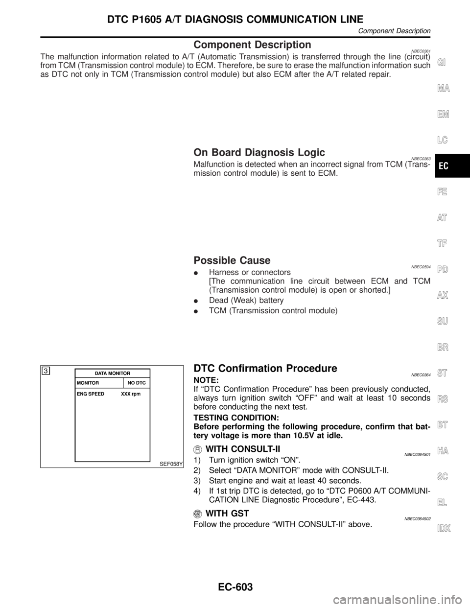
Component DescriptionNBEC0361The malfunction information related to A/T (Automatic Transmission) is transferred through the line (circuit)
from TCM (Transmission control module) to ECM. Therefore, be sure to erase the malfunction information such
as DTC not only in TCM (Transmission control module) but also ECM after the A/T related repair.
On Board Diagnosis LogicNBEC0363Malfunction is detected when an incorrect signal from TCM (Trans-
mission control module) is sent to ECM.
Possible CauseNBEC0594IHarness or connectors
[The communication line circuit between ECM and TCM
(Transmission control module) is open or shorted.]
IDead (Weak) battery
ITCM (Transmission control module)
SEF058Y
DTC Confirmation ProcedureNBEC0364NOTE:
If ªDTC Confirmation Procedureº has been previously conducted,
always turn ignition switch ªOFFº and wait at least 10 seconds
before conducting the next test.
TESTING CONDITION:
Before performing the following procedure, confirm that bat-
tery voltage is more than 10.5V at idle.
WITH CONSULT-IINBEC0364S011) Turn ignition switch ªONº.
2) Select ªDATA MONITORº mode with CONSULT-II.
3) Start engine and wait at least 40 seconds.
4) If 1st trip DTC is detected, go to ªDTC P0600 A/T COMMUNI-
CATION LINE Diagnostic Procedureº, EC-443.
WITH GSTNBEC0364S02Follow the procedure ªWITH CONSULT-IIº above.
GI
MA
EM
LC
FE
AT
TF
PD
AX
SU
BR
ST
RS
BT
HA
SC
EL
IDX
DTC P1605 A/T DIAGNOSIS COMMUNICATION LINE
Component Description
EC-603
Page 1145 of 2395
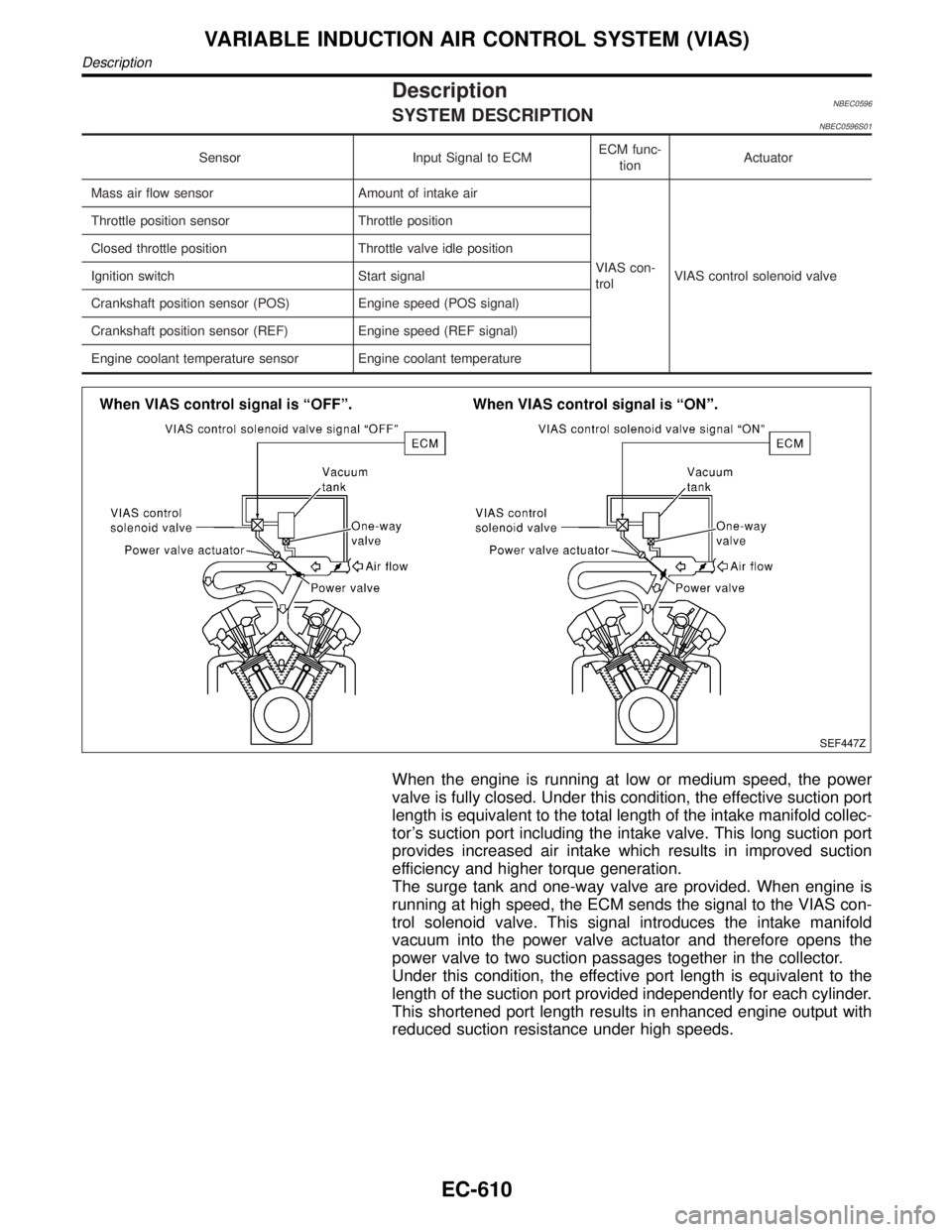
DescriptionNBEC0596SYSTEM DESCRIPTIONNBEC0596S01
Sensor Input Signal to ECMECM func-
tionActuator
Mass air flow sensor Amount of intake air
VIAS con-
trolVIAS control solenoid valve Throttle position sensor Throttle position
Closed throttle position Throttle valve idle position
Ignition switch Start signal
Crankshaft position sensor (POS) Engine speed (POS signal)
Crankshaft position sensor (REF) Engine speed (REF signal)
Engine coolant temperature sensor Engine coolant temperature
SEF447Z
When the engine is running at low or medium speed, the power
valve is fully closed. Under this condition, the effective suction port
length is equivalent to the total length of the intake manifold collec-
tor's suction port including the intake valve. This long suction port
provides increased air intake which results in improved suction
efficiency and higher torque generation.
The surge tank and one-way valve are provided. When engine is
running at high speed, the ECM sends the signal to the VIAS con-
trol solenoid valve. This signal introduces the intake manifold
vacuum into the power valve actuator and therefore opens the
power valve to two suction passages together in the collector.
Under this condition, the effective port length is equivalent to the
length of the suction port provided independently for each cylinder.
This shortened port length results in enhanced engine output with
reduced suction resistance under high speeds.
VARIABLE INDUCTION AIR CONTROL SYSTEM (VIAS)
Description
EC-610
Page 1146 of 2395
SEF018Z
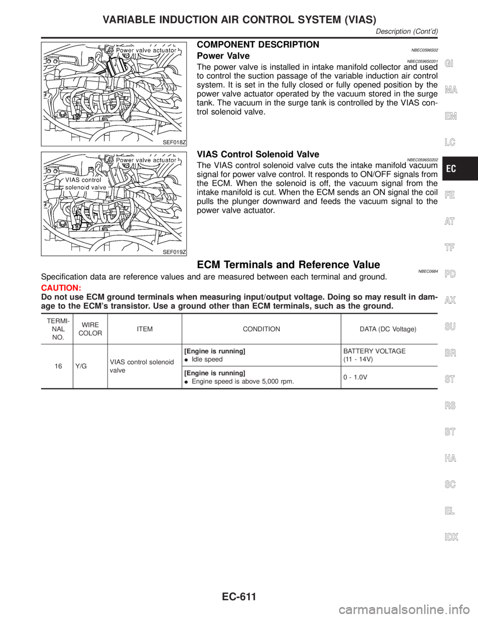
COMPONENT DESCRIPTIONNBEC0596S02Power ValveNBEC0596S0201The power valve is installed in intake manifold collector and used
to control the suction passage of the variable induction air control
system. It is set in the fully closed or fully opened position by the
power valve actuator operated by the vacuum stored in the surge
tank. The vacuum in the surge tank is controlled by the VIAS con-
trol solenoid valve.
SEF019Z
VIAS Control Solenoid ValveNBEC0596S0202The VIAS control solenoid valve cuts the intake manifold vacuum
signal for power valve control. It responds to ON/OFF signals from
the ECM. When the solenoid is off, the vacuum signal from the
intake manifold is cut. When the ECM sends an ON signal the coil
pulls the plunger downward and feeds the vacuum signal to the
power valve actuator.
ECM Terminals and Reference ValueNBEC0684Specification data are reference values and are measured between each terminal and ground.
CAUTION:
Do not use ECM ground terminals when measuring input/output voltage. Doing so may result in dam-
age to the ECM's transistor. Use a ground other than ECM terminals, such as the ground.
TERMI-
NAL
NO.WIRE
COLORITEM CONDITION DATA (DC Voltage)
16 Y/GVIAS control solenoid
valve[Engine is running]
IIdle speedBATTERY VOLTAGE
(11 - 14V)
[Engine is running]
IEngine speed is above 5,000 rpm.0 - 1.0V
GI
MA
EM
LC
FE
AT
TF
PD
AX
SU
BR
ST
RS
BT
HA
SC
EL
IDX
VARIABLE INDUCTION AIR CONTROL SYSTEM (VIAS)
Description (Cont'd)
EC-611
Page 1151 of 2395
SEF375Z
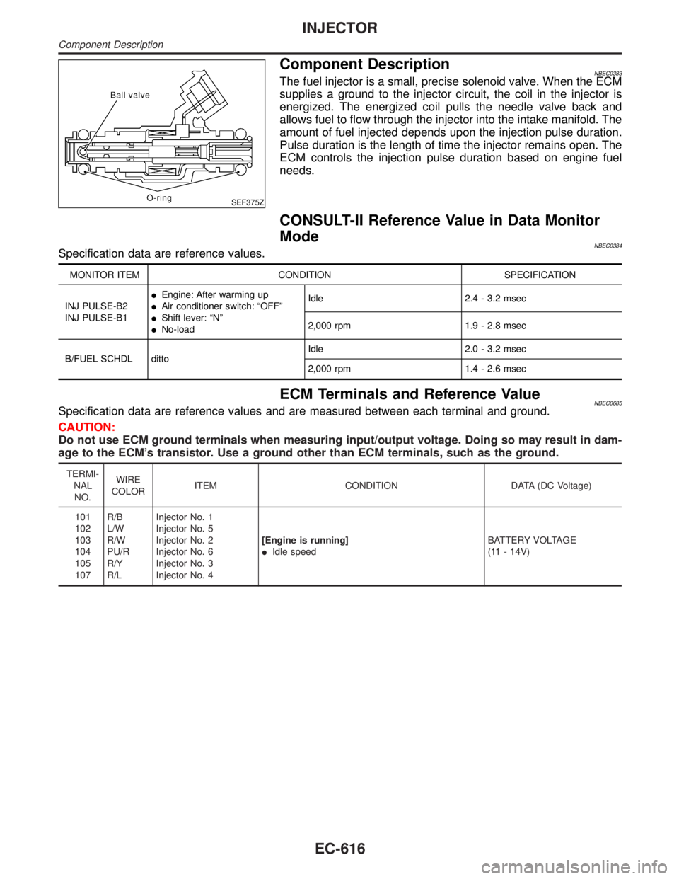
Component DescriptionNBEC0383The fuel injector is a small, precise solenoid valve. When the ECM
supplies a ground to the injector circuit, the coil in the injector is
energized. The energized coil pulls the needle valve back and
allows fuel to flow through the injector into the intake manifold. The
amount of fuel injected depends upon the injection pulse duration.
Pulse duration is the length of time the injector remains open. The
ECM controls the injection pulse duration based on engine fuel
needs.
CONSULT-II Reference Value in Data Monitor
Mode
NBEC0384Specification data are reference values.
MONITOR ITEM CONDITION SPECIFICATION
INJ PULSE-B2
INJ PULSE-B1IEngine: After warming up
IAir conditioner switch: ªOFFº
IShift lever: ªNº
INo-loadIdle 2.4 - 3.2 msec
2,000 rpm 1.9 - 2.8 msec
B/FUEL SCHDL dittoIdle 2.0 - 3.2 msec
2,000 rpm 1.4 - 2.6 msec
ECM Terminals and Reference ValueNBEC0685Specification data are reference values and are measured between each terminal and ground.
CAUTION:
Do not use ECM ground terminals when measuring input/output voltage. Doing so may result in dam-
age to the ECM's transistor. Use a ground other than ECM terminals, such as the ground.
TERMI-
NAL
NO.WIRE
COLORITEM CONDITION DATA (DC Voltage)
101
102
103
104
105
107R/B
L/W
R/W
PU/R
R/Y
R/LInjector No. 1
Injector No. 5
Injector No. 2
Injector No. 6
Injector No. 3
Injector No. 4[Engine is running]
IIdle speedBATTERY VOLTAGE
(11 - 14V)
INJECTOR
Component Description
EC-616
Page 1174 of 2395
SEF029Z
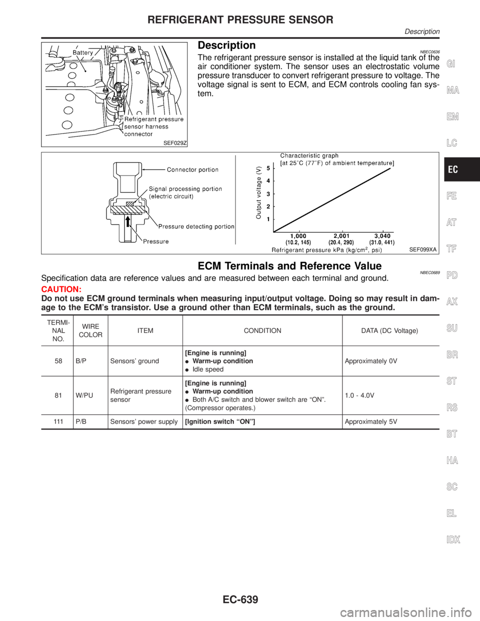
DescriptionNBEC0636The refrigerant pressure sensor is installed at the liquid tank of the
air conditioner system. The sensor uses an electrostatic volume
pressure transducer to convert refrigerant pressure to voltage. The
voltage signal is sent to ECM, and ECM controls cooling fan sys-
tem.
SEF099XA
ECM Terminals and Reference ValueNBEC0689Specification data are reference values and are measured between each terminal and ground.
CAUTION:
Do not use ECM ground terminals when measuring input/output voltage. Doing so may result in dam-
age to the ECM's transistor. Use a ground other than ECM terminals, such as the ground.
TERMI-
NAL
NO.WIRE
COLORITEM CONDITION DATA (DC Voltage)
58 B/P Sensors' ground[Engine is running]
IWarm-up condition
IIdle speedApproximately 0V
81 W/PURefrigerant pressure
sensor[Engine is running]
IWarm-up condition
IBoth A/C switch and blower switch are ªONº.
(Compressor operates.)1.0 - 4.0V
111 P/B Sensors' power supply[Ignition switch ªONº]Approximately 5V
GI
MA
EM
LC
FE
AT
TF
PD
AX
SU
BR
ST
RS
BT
HA
SC
EL
IDX
REFRIGERANT PRESSURE SENSOR
Description
EC-639
Page 1184 of 2395
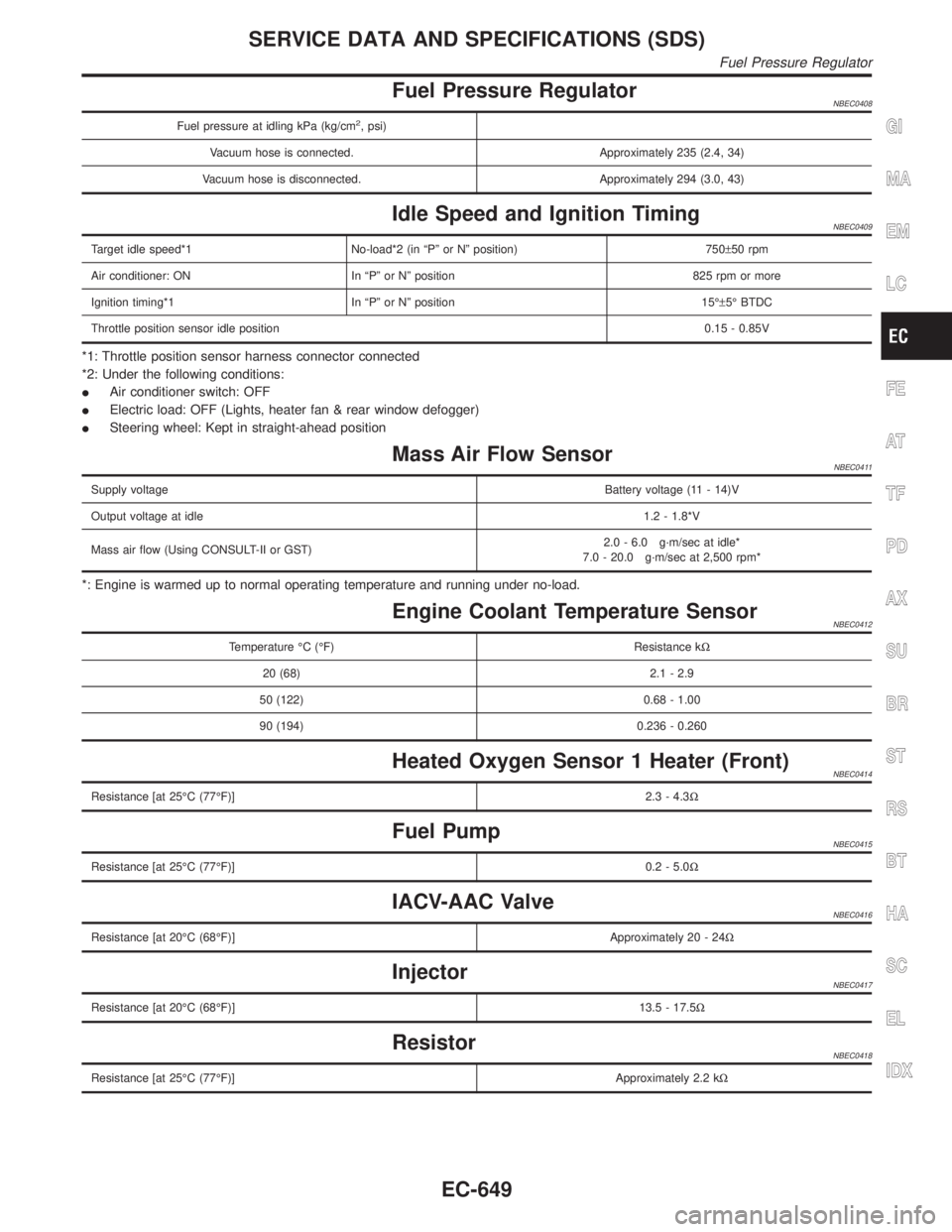
Fuel Pressure RegulatorNBEC0408
Fuel pressure at idling kPa (kg/cm2, psi)
Vacuum hose is connected. Approximately 235 (2.4, 34)
Vacuum hose is disconnected. Approximately 294 (3.0, 43)
Idle Speed and Ignition TimingNBEC0409
Target idle speed*1 No-load*2 (in ªPº or Nº position) 750±50 rpm
Air conditioner: ON In ªPº or Nº position 825 rpm or more
Ignition timing*1 In ªPº or Nº position 15ɱ5É BTDC
Throttle position sensor idle position0.15 - 0.85V
*1: Throttle position sensor harness connector connected
*2: Under the following conditions:
IAir conditioner switch: OFF
IElectric load: OFF (Lights, heater fan & rear window defogger)
ISteering wheel: Kept in straight-ahead position
Mass Air Flow SensorNBEC0411
Supply voltageBattery voltage (11 - 14)V
Output voltage at idle1.2 - 1.8*V
Mass air flow (Using CONSULT-II or GST)2.0 - 6.0 g´m/sec at idle*
7.0 - 20.0 g´m/sec at 2,500 rpm*
*: Engine is warmed up to normal operating temperature and running under no-load.
Engine Coolant Temperature SensorNBEC0412
Temperature ÉC (ÉF) Resistance kW
20 (68) 2.1 - 2.9
50 (122) 0.68 - 1.00
90 (194) 0.236 - 0.260
Heated Oxygen Sensor 1 Heater (Front)NBEC0414
Resistance [at 25ÉC (77ÉF)]2.3 - 4.3W
Fuel PumpNBEC0415
Resistance [at 25ÉC (77ÉF)]0.2 - 5.0W
IACV-AAC ValveNBEC0416
Resistance [at 20ÉC (68ÉF)]Approximately 20 - 24W
InjectorNBEC0417
Resistance [at 20ÉC (68ÉF)]13.5 - 17.5W
ResistorNBEC0418
Resistance [at 25ÉC (77ÉF)]Approximately 2.2 kW
GI
MA
EM
LC
FE
AT
TF
PD
AX
SU
BR
ST
RS
BT
HA
SC
EL
IDX
SERVICE DATA AND SPECIFICATIONS (SDS)
Fuel Pressure Regulator
EC-649