2001 DODGE TOWN AND COUNTRY torque
[x] Cancel search: torquePage 1647 of 2321
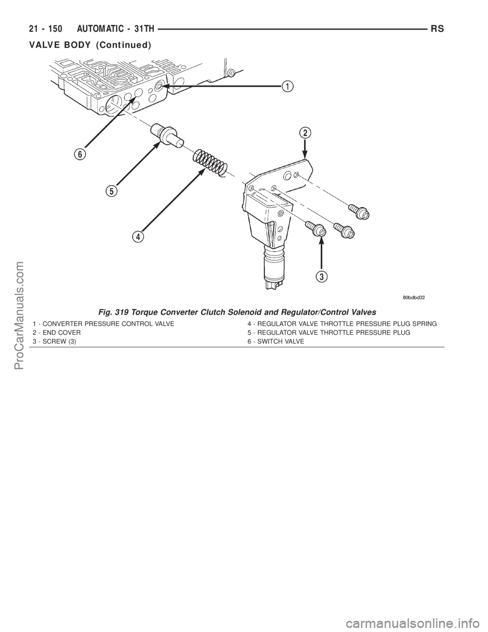
Fig. 319 Torque Converter Clutch Solenoid and Regulator/Control Valves
1 - CONVERTER PRESSURE CONTROL VALVE
2 - END COVER
3 - SCREW (3)4 - REGULATOR VALVE THROTTLE PRESSURE PLUG SPRING
5 - REGULATOR VALVE THROTTLE PRESSURE PLUG
6 - SWITCH VALVE
21 - 150 AUTOMATIC - 31THRS
VALVE BODY (Continued)
ProCarManuals.com
Page 1648 of 2321
CLEANING
Clean the valve body components in a parts clean-
ing solution only. Do not use gasoline, kerosene, or
any type of caustic solution. Dry the parts with com-
pressed air. Make sure all passages are clean and
free from obstructions.
NOTE: Do not use rags or shop towels to wipe off
valve body components. Lint from these materials
will adhere to the valve body components. Lint will
interfere with valve operation and may clog filters
and fluid passages.
Minor distortion of a valve body mating surface
may be corrected by smoothing the surface with cro-
cus cloth. The cloth should be in sheet form and be
positioned on a surface plate, sheet of plate glass, or
equally flat surface. However, if distortion is severeor any surfaces are heavily scored, the valve body
will have to be replaced.
CAUTION: Many of the valve body valves and plugs
are made of coated aluminum. Aluminum compo-
nents can be identified by the dark color of the spe-
cial coating applied to the surface (or by testing
with a magnet). DO NOT polish or sand aluminum
valves or plugs with any type of material, or under
any circumstances. This practice might damage the
special coating and cause the valves and plugs to
stick and bind.
Aluminum valves and plugs should not be sanded
or polished under any circumstances. However, minor
burrs or scratches on steel valves and plugs can be
removed with crocus cloth but do not round off the
valve or plug edges. Squareness of these edges is
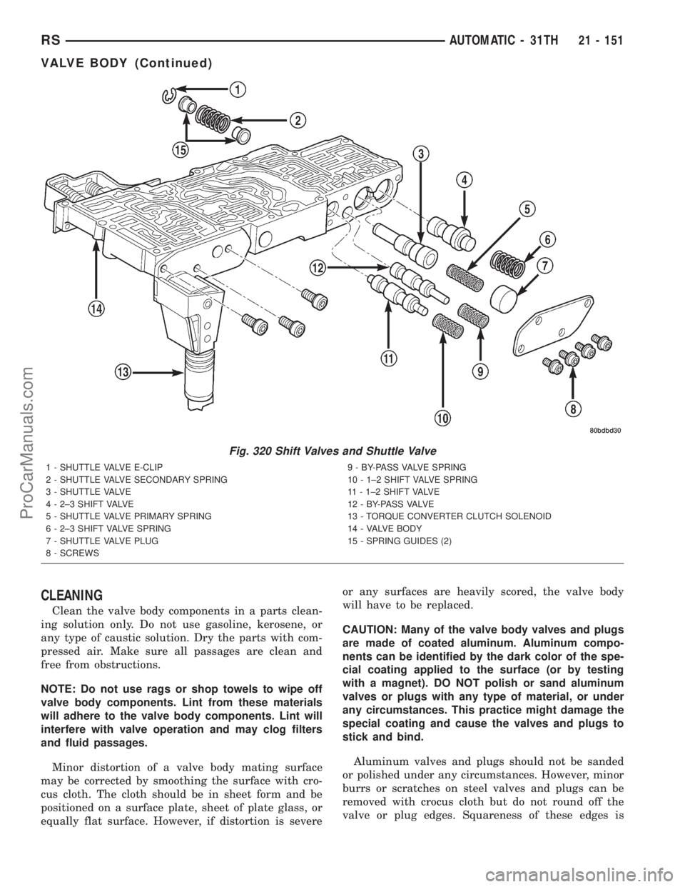
Fig. 320 Shift Valves and Shuttle Valve
1 - SHUTTLE VALVE E-CLIP
2 - SHUTTLE VALVE SECONDARY SPRING
3 - SHUTTLE VALVE
4 - 2±3 SHIFT VALVE
5 - SHUTTLE VALVE PRIMARY SPRING
6 - 2±3 SHIFT VALVE SPRING
7 - SHUTTLE VALVE PLUG
8 - SCREWS9 - BY-PASS VALVE SPRING
10 - 1±2 SHIFT VALVE SPRING
11 - 1±2 SHIFT VALVE
1 2 - B Y- PA S S VA LV E
13 - TORQUE CONVERTER CLUTCH SOLENOID
14 - VALVE BODY
15 - SPRING GUIDES (2)
RSAUTOMATIC - 31TH21 - 151
VALVE BODY (Continued)
ProCarManuals.com
Page 1649 of 2321
vitally important. These edges prevent foreign matter
from lodging between the valves, plugs and bore.
INSPECTION
Inspect the throttle and manual valve levers and
shafts. Do not attempt to straighten a bent shaft or
correct a loose lever. Replace these components if
worn, bent, loose or damaged in any way.
Inspect all of the valve body mating surfaces for
scratches, nicks, burrs, or distortion. Use a straight-
edge to check surface flatness. Minor scratches may
be removed with crocus cloth using only very light
pressure.
Inspect the valves and plugs for scratches, burrs,
nicks, or scores. Also inspect the coating on the alu-
minum valves and plugs. If the coating is damaged
or worn through, the valve (or valve body) should be
replaced.
Inspect all the valve and plug bores in the valve
body. Use a penlight to view the bore interiors.
Replace the valve body if any bores are distorted or
scored. Inspect all of the valve body springs. The
springs must be free of distortion, warpage or broken
coils.
Trial fit each valve and plug in its bore to check
freedom of operation. When clean and dry, the valves
and plugs should drop freely into the bores. Valve
body bores do not change dimensionally with use. If
the valve body functioned correctly when new, it will
continue to operate properly after cleaning and
inspection. It should not be necessary to replace a
valve body assembly unless it is damaged in han-
dling.
ASSEMBLY
(1) Install shift/shuttle valves and springs as
shown in (Fig. 320).
(2) Install torque converter clutch solenoid, spring,
and plug as shown in (Fig. 319).
(3) Install governor plugs as shown in (Fig. 318).
(4) Install pressure regulator and manual control
springs and valves as shown in (Fig. 317).
(5) Install pressure regulator spring retainer/ad-
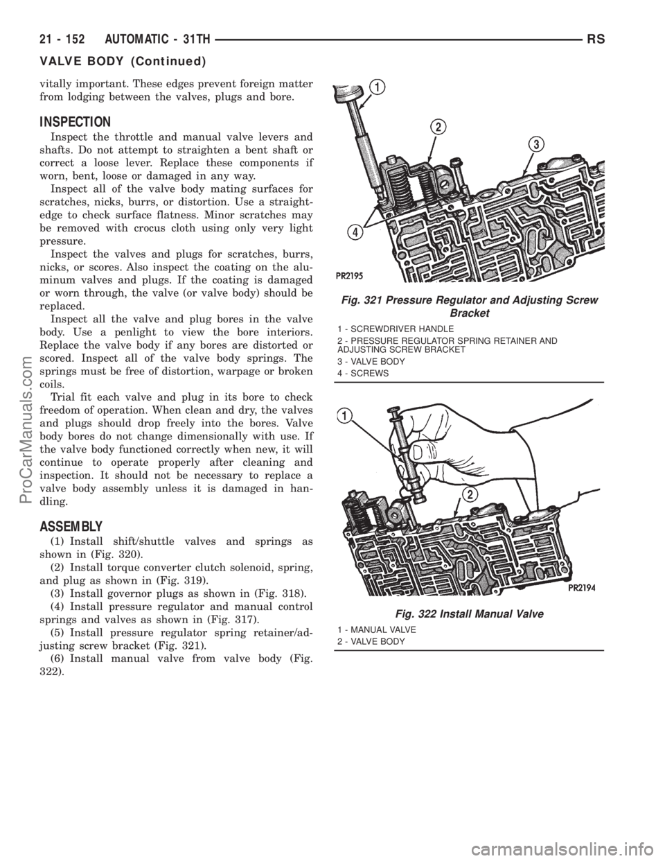
justing screw bracket (Fig. 321).
(6) Install manual valve from valve body (Fig.
322).
Fig. 321 Pressure Regulator and Adjusting Screw
Bracket
1 - SCREWDRIVER HANDLE
2 - PRESSURE REGULATOR SPRING RETAINER AND
ADJUSTING SCREW BRACKET
3 - VALVE BODY
4 - SCREWS
Fig. 322 Install Manual Valve
1 - MANUAL VALVE
2 - VALVE BODY
21 - 152 AUTOMATIC - 31THRS
VALVE BODY (Continued)
ProCarManuals.com
Page 1651 of 2321
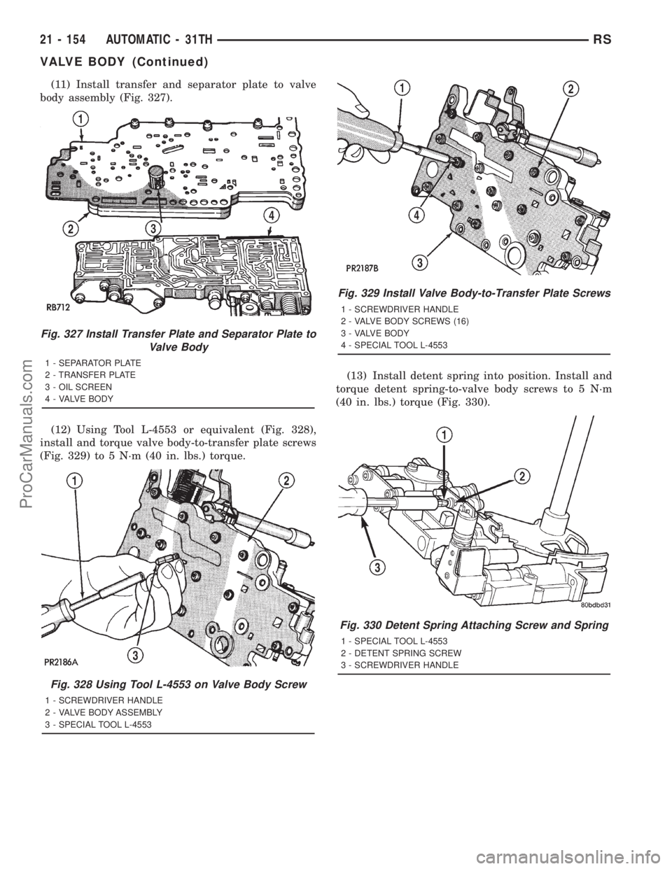
(11) Install transfer and separator plate to valve
body assembly (Fig. 327).
(12) Using Tool L-4553 or equivalent (Fig. 328),
install and torque valve body-to-transfer plate screws
(Fig. 329) to 5 N´m (40 in. lbs.) torque.(13) Install detent spring into position. Install and
torque detent spring-to-valve body screws to 5 N´m
(40 in. lbs.) torque (Fig. 330).
Fig. 327 Install Transfer Plate and Separator Plate to
Valve Body
1 - SEPARATOR PLATE
2 - TRANSFER PLATE
3 - OIL SCREEN
4 - VALVE BODY
Fig. 328 Using Tool L-4553 on Valve Body Screw
1 - SCREWDRIVER HANDLE
2 - VALVE BODY ASSEMBLY
3 - SPECIAL TOOL L-4553
Fig. 329 Install Valve Body-to-Transfer Plate Screws
1 - SCREWDRIVER HANDLE
2 - VALVE BODY SCREWS (16)
3 - VALVE BODY
4 - SPECIAL TOOL L-4553
Fig. 330 Detent Spring Attaching Screw and Spring
1 - SPECIAL TOOL L-4553
2 - DETENT SPRING SCREW
3 - SCREWDRIVER HANDLE
21 - 154 AUTOMATIC - 31THRS
VALVE BODY (Continued)
ProCarManuals.com
Page 1652 of 2321
INSTALLATION
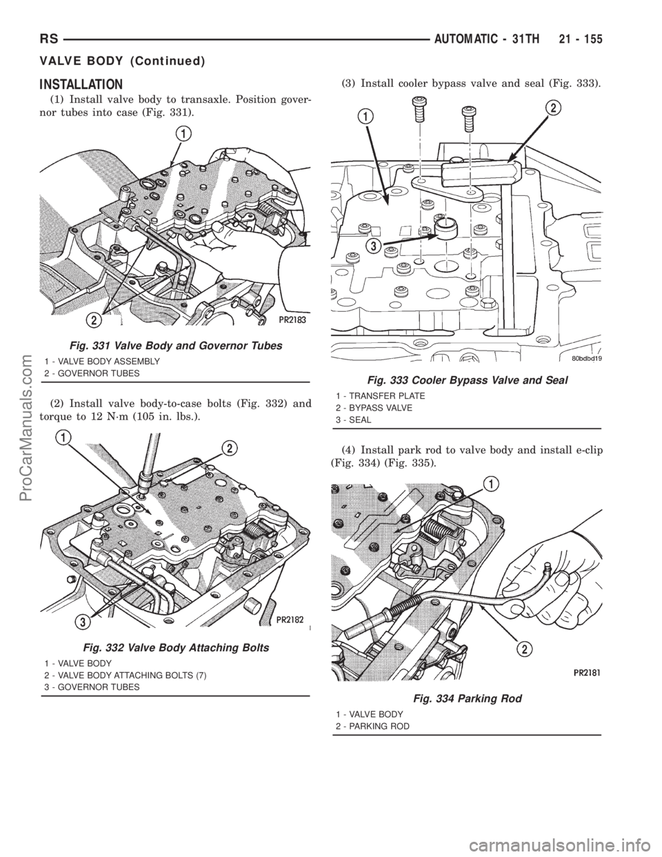
(1) Install valve body to transaxle. Position gover-
nor tubes into case (Fig. 331).
(2) Install valve body-to-case bolts (Fig. 332) and
torque to 12 N´m (105 in. lbs.).(3) Install cooler bypass valve and seal (Fig. 333).
(4) Install park rod to valve body and install e-clip
(Fig. 334) (Fig. 335).
Fig. 331 Valve Body and Governor Tubes
1 - VALVE BODY ASSEMBLY
2 - GOVERNOR TUBES
Fig. 332 Valve Body Attaching Bolts
1 - VALVE BODY
2 - VALVE BODY ATTACHING BOLTS (7)
3 - GOVERNOR TUBES
Fig. 333 Cooler Bypass Valve and Seal
1 - TRANSFER PLATE
2 - BYPASS VALVE
3 - SEAL
Fig. 334 Parking Rod
1 - VALVE BODY
2 - PARKING ROD
RSAUTOMATIC - 31TH21 - 155
VALVE BODY (Continued)
ProCarManuals.com
Page 1653 of 2321
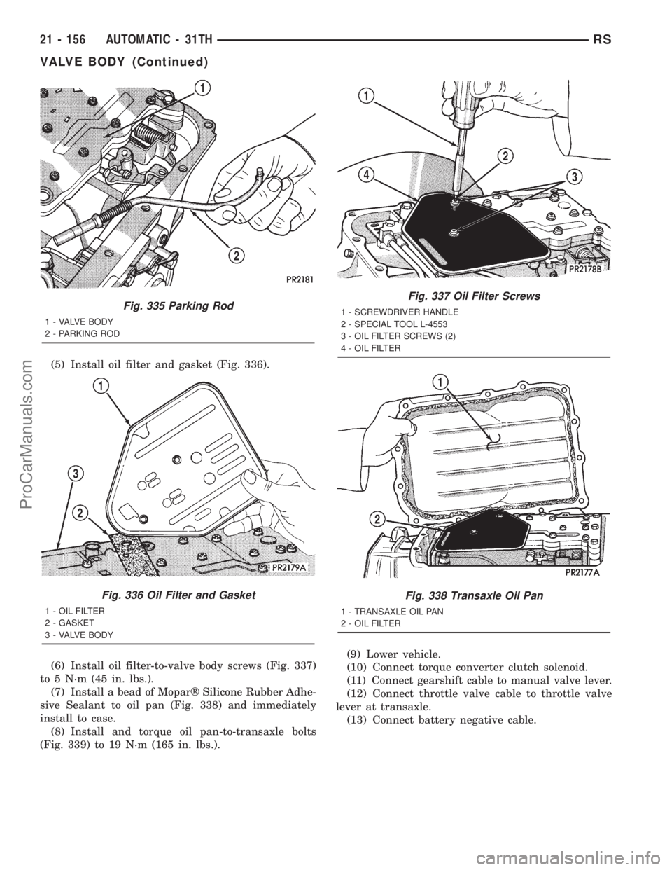
(5) Install oil filter and gasket (Fig. 336).
(6) Install oil filter-to-valve body screws (Fig. 337)
to 5 N´m (45 in. lbs.).
(7) Install a bead of Moparž Silicone Rubber Adhe-
sive Sealant to oil pan (Fig. 338) and immediately
install to case.
(8) Install and torque oil pan-to-transaxle bolts
(Fig. 339) to 19 N´m (165 in. lbs.).(9) Lower vehicle.
(10) Connect torque converter clutch solenoid.
(11) Connect gearshift cable to manual valve lever.
(12) Connect throttle valve cable to throttle valve
lever at transaxle.
(13) Connect battery negative cable.
Fig. 335 Parking Rod
1 - VALVE BODY
2 - PARKING ROD
Fig. 336 Oil Filter and Gasket
1 - OIL FILTER
2 - GASKET
3 - VALVE BODY
Fig. 337 Oil Filter Screws
1 - SCREWDRIVER HANDLE
2 - SPECIAL TOOL L-4553
3 - OIL FILTER SCREWS (2)
4 - OIL FILTER
Fig. 338 Transaxle Oil Pan
1 - TRANSAXLE OIL PAN
2 - OIL FILTER
21 - 156 AUTOMATIC - 31THRS
VALVE BODY (Continued)
ProCarManuals.com
Page 1654 of 2321
HYDRAULIC CONTROL PRESSURE
ADJUSTMENTS
LINE PRESSURE
An incorrect throttle pressure setting will cause
incorrect line pressure readings even though line
pressure adjustment is correct. Always inspect and
correct throttle pressure adjustment before adjusting
the line pressure.
The approximate adjustment for line pressure is
1-5/16 inches, measured from valve body to inner
edge of adjusting nut. However, due to manufactur-
ing tolerances, the adjustment can be varied to
obtain specified line pressure.
The adjusting screw may be turned with an Allen
wrench. One complete turn of adjusting screw
changes closed throttle line pressure approximately
1-2/3 psi. Turning adjusting screw counterclockwise
increases pressure, and clockwise decreases pressure.
THROTTLE PRESSURE
Throttle pressures cannot be tested accurately;
therefore, the adjustment should be measured if a
malfunction is evident.
(1) Insert gauge pin of Tool C-3763 between the
throttle lever cam and kickdown valve.
(2) By pushing in on tool, compress kickdown
valve against its spring so throttle valve is com-
pletely bottomed inside the valve body.
(3) While compressing spring, turn throttle lever
stop screw with adapter C-4553. Turn until head of
screw touches throttle lever tang, with throttle lever
cam touching tool and throttle valve bottomed. Be
sure adjustment is made with spring fully com-
pressed and valve bottomed in the valve body.
VEHICLE SPEED SENSOR/
PINION GEAR
REMOVAL
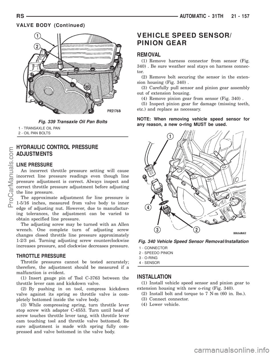
(1) Remove harness connector from sensor (Fig.
340) . Be sure weather seal stays on harness connec-
tor.
(2) Remove bolt securing the sensor in the exten-
sion housing (Fig. 340) .
(3) Carefully pull sensor and pinion gear assembly
out of extension housing.
(4) Remove pinion gear from sensor (Fig. 340) .
(5) Inspect pinion gear for damage (missing teeth,
etc.) and replace as necessary.
NOTE: When removing vehicle speed sensor for
any reason, a new o-ring MUST be used.
INSTALLATION
(1) Install vehicle speed sensor and pinion gear to
extension housing with new o-ring (Fig. 340).
(2) Install bolt and torque to 7 N´m (60 in. lbs.).
(3) Connect connector.
(4) Lower vehicle.
Fig. 339 Transaxle Oil Pan Bolts
1 - TRANSAXLE OIL PAN
2 - OIL PAN BOLTS
Fig. 340 Vehicle Speed Sensor Removal/Installation
1 - CONNECTOR
2 - SPEEDO PINION
3 - O-RING
4 - SENSOR
RSAUTOMATIC - 31TH21 - 157
VALVE BODY (Continued)
ProCarManuals.com
Page 1655 of 2321
AUTOMATIC - 41TE
TABLE OF CONTENTS
page page
AUTOMATIC - 41TE
DESCRIPTION..........................159
OPERATION............................159
DIAGNOSIS AND TESTING................159
41TE TRANSAXLE GENERAL DIAGNOSIS . . . 159
ROAD TEST..........................161
HYDRAULIC PRESSURE TESTS..........162
CLUTCH AIR PRESSURE TESTS..........164
TORQUE CONVERTER HOUSING FLUID
LEAKAGE............................164
REMOVAL.............................165
DISASSEMBLY..........................169
ASSEMBLY............................186
INSTALLATION..........................209
SCHEMATICS AND DIAGRAMS.............212
SPECIFICATIONS........................225
SPECIAL TOOLS........................227
ACCUMULATOR
DESCRIPTION..........................232
OPERATION............................233
AUTOSTICK SWITCH
DESCRIPTION..........................233
OPERATION............................233
DRIVING CLUTCHES
DESCRIPTION..........................234
OPERATION............................234
FINAL DRIVE
DESCRIPTION..........................234
OPERATION............................234
DISASSEMBLY..........................235
ASSEMBLY............................240
ADJUSTMENTS.........................243
FLUID
STANDARD PROCEDURE.................246
FLUID LEVEL AND CONDITION CHECK.....246
FLUID AND FILTER SERVICE.............246
GEAR SHIFT CABLE
REMOVAL.............................248
INSTALLATION..........................250
ADJUSTMENTS.........................251
HOLDING CLUTCHES
DESCRIPTION..........................251
OPERATION............................251
INPUT CLUTCH ASSEMBLY
DISASSEMBLY..........................252
ASSEMBLY............................259
OIL PUMP
DESCRIPTION..........................269
OPERATION............................269STANDARD PROCEDURE.................269
OIL PUMP VOLUME CHECK..............269
DISASSEMBLY..........................270
ASSEMBLY............................271
PLANETARY GEARTRAIN
DESCRIPTION..........................271
OPERATION............................271
SEAL - OIL PUMP
REMOVAL.............................271
INSTALLATION..........................272
SHIFT INTERLOCK SOLENOID
DESCRIPTION..........................272
OPERATION............................273
DIAGNOSIS AND TESTING................274
BRAKE/TRANSMISSION SHIFT INTERLOCK
SOLENOID...........................274
REMOVAL.............................274
INSTALLATION..........................275
SOLENOID/PRESSURE SWITCH ASSEMBLY
DESCRIPTION..........................276
OPERATION............................276
REMOVAL.............................277
INSTALLATION..........................277
SPEED SENSOR - INPUT
DESCRIPTION..........................278
OPERATION............................278
REMOVAL.............................279
INSTALLATION..........................279
SPEED SENSOR - OUTPUT
DESCRIPTION..........................280
OPERATION............................280
REMOVAL.............................280
INSTALLATION..........................281
TORQUE CONVERTER
DESCRIPTION..........................281
OPERATION............................284
REMOVAL.............................286
INSTALLATION..........................286
TRANSMISSION CONTROL RELAY
DESCRIPTION..........................287
OPERATION............................287
TRANSMISSION RANGE SENSOR
DESCRIPTION..........................287
OPERATION............................287
REMOVAL.............................288
INSTALLATION..........................288
TORQUE REDUCTION LINK (TRD)
DESCRIPTION..........................289
OPERATION............................289
21 - 158 AUTOMATIC - 41TERS
ProCarManuals.com