2001 DODGE TOWN AND COUNTRY torque
[x] Cancel search: torquePage 1623 of 2321
TRANSFER SYSTEM - OUTPUT
SHAFT/GEAR/BEARING
REMOVAL
NOTE: Transfer Gear should be removed for repair
of output shaft, to obtain an accurate output shaft
turning torque measurement upon reassembly.
(Refer to 21 - TRANSMISSION/TRANSAXLE/AUTO-
MATIC - 31TH/TRANSFER SYSTEM - REMOVAL)
NOTE: Transaxle geartrain must be removed to gain
access to and service output shaft. (Refer to 21 -
TRANSMISSION/TRANSAXLE/AUTOMATIC - 31TH -
DISASSEMBLY)
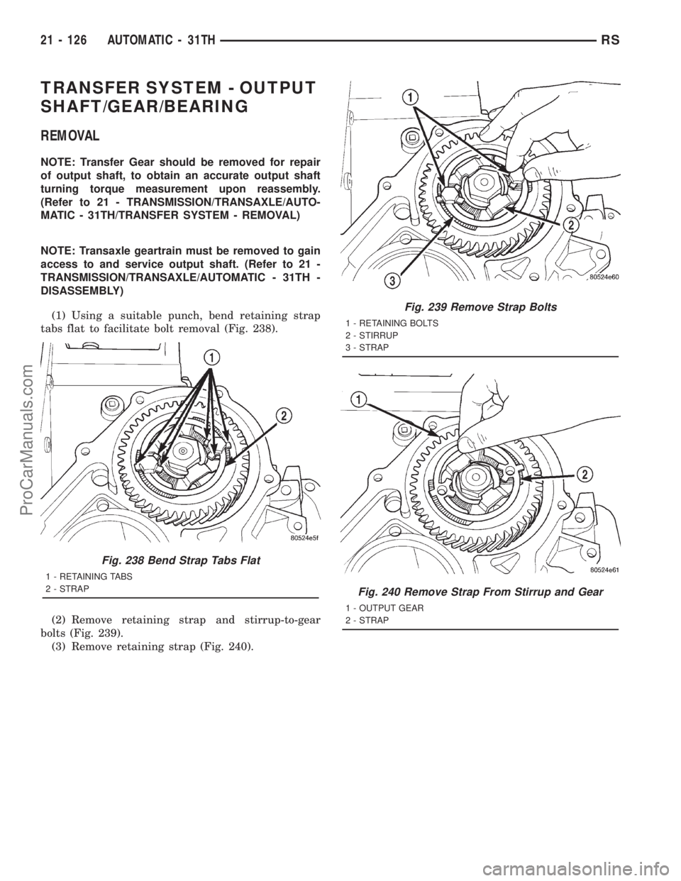
(1) Using a suitable punch, bend retaining strap
tabs flat to facilitate bolt removal (Fig. 238).
(2) Remove retaining strap and stirrup-to-gear
bolts (Fig. 239).
(3) Remove retaining strap (Fig. 240).
Fig. 238 Bend Strap Tabs Flat
1 - RETAINING TABS
2 - STRAP
Fig. 239 Remove Strap Bolts
1 - RETAINING BOLTS
2 - STIRRUP
3 - STRAP
Fig. 240 Remove Strap From Stirrup and Gear
1 - OUTPUT GEAR
2 - STRAP
21 - 126 AUTOMATIC - 31THRS
ProCarManuals.com
Page 1627 of 2321
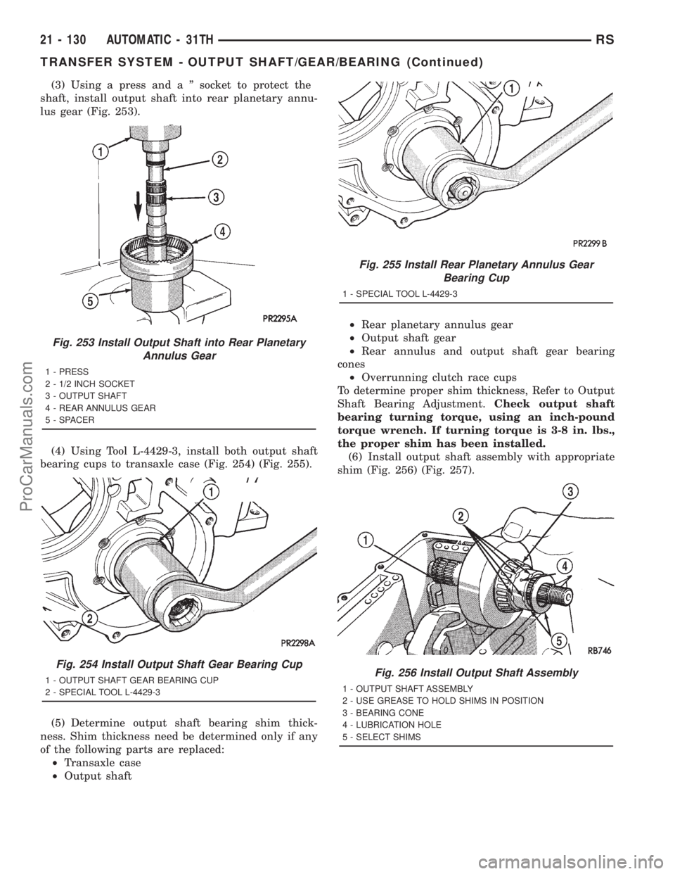
(3) Using a press and a º socket to protect the
shaft, install output shaft into rear planetary annu-
lus gear (Fig. 253).
(4) Using Tool L-4429-3, install both output shaft
bearing cups to transaxle case (Fig. 254) (Fig. 255).
(5) Determine output shaft bearing shim thick-
ness. Shim thickness need be determined only if any
of the following parts are replaced:
²Transaxle case
²Output shaft²Rear planetary annulus gear
²Output shaft gear
²Rear annulus and output shaft gear bearing
cones
²Overrunning clutch race cups
To determine proper shim thickness, Refer to Output
Shaft Bearing Adjustment.Check output shaft
bearing turning torque, using an inch-pound
torque wrench. If turning torque is 3-8 in. lbs.,
the proper shim has been installed.
(6) Install output shaft assembly with appropriate
shim (Fig. 256) (Fig. 257).
Fig. 253 Install Output Shaft into Rear Planetary
Annulus Gear
1 - PRESS
2 - 1/2 INCH SOCKET
3 - OUTPUT SHAFT
4 - REAR ANNULUS GEAR
5 - SPACER
Fig. 254 Install Output Shaft Gear Bearing Cup
1 - OUTPUT SHAFT GEAR BEARING CUP
2 - SPECIAL TOOL L-4429-3
Fig. 255 Install Rear Planetary Annulus Gear
Bearing Cup
1 - SPECIAL TOOL L-4429-3
Fig. 256 Install Output Shaft Assembly
1 - OUTPUT SHAFT ASSEMBLY
2 - USE GREASE TO HOLD SHIMS IN POSITION
3 - BEARING CONE
4 - LUBRICATION HOLE
5 - SELECT SHIMS
21 - 130 AUTOMATIC - 31THRS
TRANSFER SYSTEM - OUTPUT SHAFT/GEAR/BEARING (Continued)
ProCarManuals.com
Page 1628 of 2321
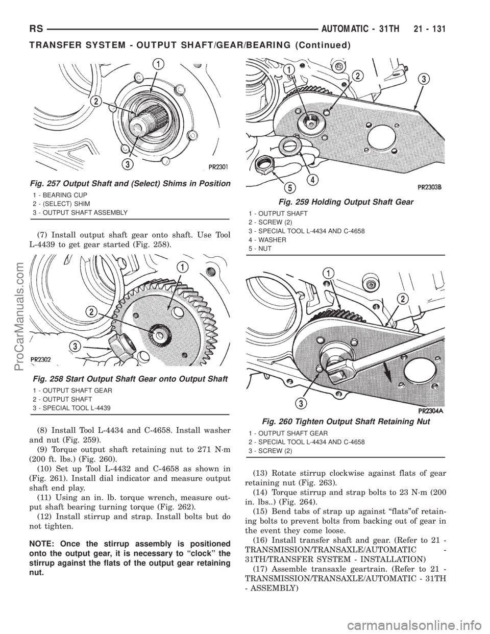
(7) Install output shaft gear onto shaft. Use Tool
L-4439 to get gear started (Fig. 258).
(8) Install Tool L-4434 and C-4658. Install washer
and nut (Fig. 259).
(9) Torque output shaft retaining nut to 271 N´m
(200 ft. lbs.) (Fig. 260).
(10) Set up Tool L-4432 and C-4658 as shown in
(Fig. 261). Install dial indicator and measure output
shaft end play.
(11) Using an in. lb. torque wrench, measure out-
put shaft bearing turning torque (Fig. 262).
(12) Install stirrup and strap. Install bolts but do
not tighten.
NOTE: Once the stirrup assembly is positioned
onto the output gear, it is necessary to ªclockº the
stirrup against the flats of the output gear retaining
nut.(13) Rotate stirrup clockwise against flats of gear
retaining nut (Fig. 263).
(14) Torque stirrup and strap bolts to 23 N´m (200
in. lbs..) (Fig. 264).
(15) Bend tabs of strap up against ªflatsºof retain-
ing bolts to prevent bolts from backing out of gear in
the event they come loose.
(16) Install transfer shaft and gear. (Refer to 21 -
TRANSMISSION/TRANSAXLE/AUTOMATIC -
31TH/TRANSFER SYSTEM - INSTALLATION)
(17) Assemble transaxle geartrain. (Refer to 21 -
TRANSMISSION/TRANSAXLE/AUTOMATIC - 31TH
- ASSEMBLY)
Fig. 257 Output Shaft and (Select) Shims in Position
1 - BEARING CUP
2 - (SELECT) SHIM
3 - OUTPUT SHAFT ASSEMBLY
Fig. 258 Start Output Shaft Gear onto Output Shaft
1 - OUTPUT SHAFT GEAR
2 - OUTPUT SHAFT
3 - SPECIAL TOOL L-4439
Fig. 259 Holding Output Shaft Gear
1 - OUTPUT SHAFT
2 - SCREW (2)
3 - SPECIAL TOOL L-4434 AND C-4658
4 - WASHER
5 - NUT
Fig. 260 Tighten Output Shaft Retaining Nut
1 - OUTPUT SHAFT GEAR
2 - SPECIAL TOOL L-4434 AND C-4658
3 - SCREW (2)
RSAUTOMATIC - 31TH21 - 131
TRANSFER SYSTEM - OUTPUT SHAFT/GEAR/BEARING (Continued)
ProCarManuals.com
Page 1629 of 2321
ADJUSTMENT - OUTPUT SHAFT BEARING
(1) With output shaft gear removed, install a 13.65
mm (0.537 inch) and a 1.34 mm (0.053 inch) gauging
shims on the planetary rear annulus gear hub using
grease to hold the shims in place. The 13.65 mm
shim has a larger inside diameter and must be
installed over the output shaft first. The 1.34 mm
shim pilots on the output shaft.
(2) Install output shaft gear and bearing assembly,
torque to 271 N´m (200 ft. lbs.).
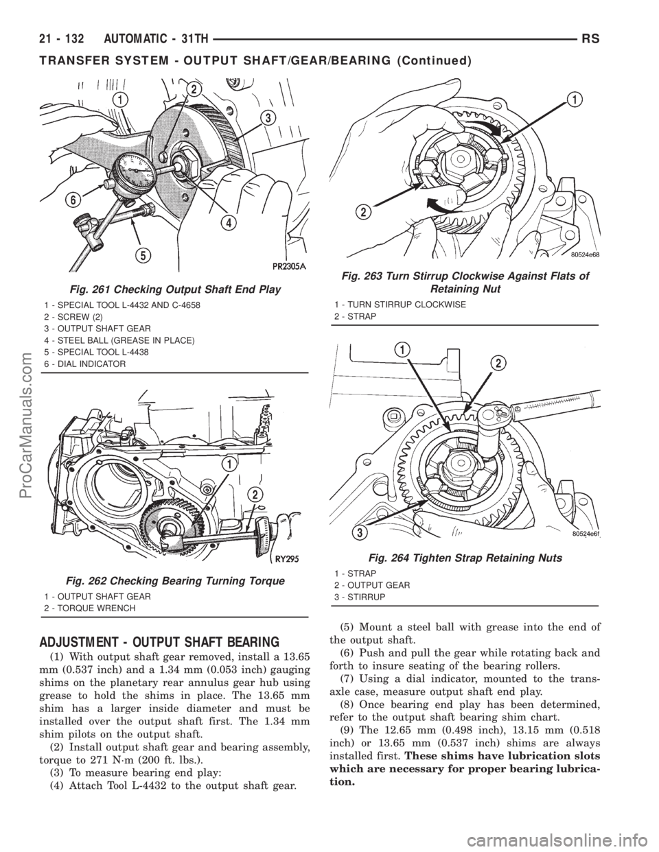
(3) To measure bearing end play:
(4) Attach Tool L-4432 to the output shaft gear.(5) Mount a steel ball with grease into the end of
the output shaft.
(6) Push and pull the gear while rotating back and
forth to insure seating of the bearing rollers.
(7) Using a dial indicator, mounted to the trans-
axle case, measure output shaft end play.
(8) Once bearing end play has been determined,
refer to the output shaft bearing shim chart.
(9) The 12.65 mm (0.498 inch), 13.15 mm (0.518
inch) or 13.65 mm (0.537 inch) shims are always
installed first.These shims have lubrication slots
which are necessary for proper bearing lubrica-
tion.
Fig. 261 Checking Output Shaft End Play
1 - SPECIAL TOOL L-4432 AND C-4658
2 - SCREW (2)
3 - OUTPUT SHAFT GEAR
4 - STEEL BALL (GREASE IN PLACE)
5 - SPECIAL TOOL L-4438
6 - DIAL INDICATOR
Fig. 262 Checking Bearing Turning Torque
1 - OUTPUT SHAFT GEAR
2 - TORQUE WRENCH
Fig. 263 Turn Stirrup Clockwise Against Flats of
Retaining Nut
1 - TURN STIRRUP CLOCKWISE
2 - STRAP
Fig. 264 Tighten Strap Retaining Nuts
1 - STRAP
2 - OUTPUT GEAR
3 - STIRRUP
21 - 132 AUTOMATIC - 31THRS
TRANSFER SYSTEM - OUTPUT SHAFT/GEAR/BEARING (Continued)
ProCarManuals.com
Page 1630 of 2321
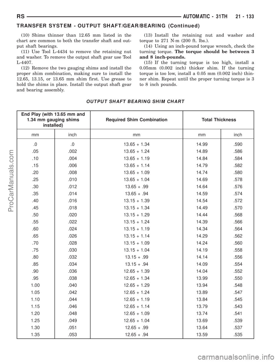
(10) Shims thinner than 12.65 mm listed in the
chart are common to both the transfer shaft and out-
put shaft bearings.
(11) Use Tool L-4434 to remove the retaining nut
and washer. To remove the output shaft gear use Tool
L-4407.
(12) Remove the two gauging shims and install the
proper shim combination, making sure to install the
12.65, 13.15, or 13.65 mm shim first. Use grease to
hold the shims in place. Install the output shaft gear
and bearing assembly.(13) Install the retaining nut and washer and
torque to 271 N´m (200 ft. lbs.).
(14) Using an inch-pound torque wrench, check the
turning torque.The torque should be between 3
and 8 inch-pounds.
(15) If the turning torque is too high, install a
0.05mm (0.002 inch) thicker shim. If the turning
torque is too low, install a 0.05 mm (0.002 inch) thin-
ner shim. Repeat until the proper turning torque is 3
to 8 inch pounds.
OUTPUT SHAFT BEARING SHIM CHART
End Play (with 13.65 mm and
1.34 mm gauging shims
installed)Required Shim Combination Total Thickness
mm inch mm mm inch
.0 .0 13.65 + 1.34 14.99 .590
.05 .002 13.65 + 1.24 14.89 .586
.10 .004 13.65 + 1.19 14.84 .584
.15 .006 13.65 + 1.14 14.79 .582
.20 .008 13.65 + 1.09 14.74 .580
.25 .010 13.65 + 1.04 14.69 .578
.30 .012 13.65 + .99 14.64 .576
.35 .014 13.65 + .94 14.59 .574
.40 .016 13.15 + 1.39 14.54 .572
.45 .018 13.15 + 1.34 14.49 .570
.50 .020 13.15 + 1.29 14.44 .568
.55 .022 13.15 + 1.24 14.39 .566
.60 .024 13.15 + 1.19 14.34 .564
.65 .026 13.15 + 1.14 14.29 .562
.70 .028 13.15 + 1.09 14.24 .560
.75 .030 13.15 + 1.04 14.19 .558
.80 .032 13.15 + .99 14.14 .556
.85 .034 13.15 + .94 14.09 .554
.90 .036 12.65 + 1.39 14.04 .552
.95 .038 12.65 + 1.34 13.99 .550
1.00 .040 12.65 + 1.29 13.94 .548
1.05 .042 12.65 + 1.24 13.89 .547
1.10 .044 12.65 + 1.19 13.84 .545
1.15 .046 12.65 + 1.14 13.79 .543
1.20 .048 12.65 + 1.09 13.74 .541
1.25 .049 12.65 + 1.04 13.69 .539
1.30 .051 12.65 + .99 13.64 .537
1.35 .053 12.65 + .94 13.59 .535
RSAUTOMATIC - 31TH21 - 133
TRANSFER SYSTEM - OUTPUT SHAFT/GEAR/BEARING (Continued)
ProCarManuals.com
Page 1638 of 2321
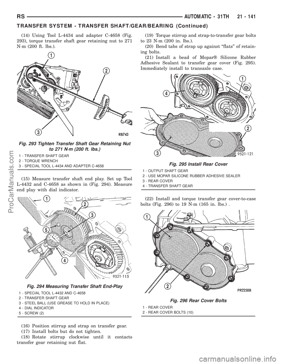
(14) Using Tool L-4434 and adapter C-4658 (Fig.
293), torque transfer shaft gear retaining nut to 271
N´m (200 ft. lbs.).
(15) Measure transfer shaft end play. Set up Tool
L-4432 and C-4658 as shown in (Fig. 294). Measure
end play with dial indicator.
(16) Position stirrup and strap on transfer gear.
(17) Install bolts but do not tighten.
(18) Rotate stirrup clockwise until it contacts
transfer gear retaining nut flat.(19) Torque stirrup and strap-to-transfer gear bolts
to 23 N´m (200 in. lbs.).
(20) Bend tabs of strap up against ªflatsº of retain-
ing bolts.
(21) Install a bead of Moparž Silicone Rubber
Adhesive Sealant to transfer gear cover (Fig. 295).
Immediately install to transaxle case.
(22) Install and torque transfer gear cover-to-case
bolts (Fig. 296) to 19 N´m (165 in. lbs.) .
Fig. 293 Tighten Transfer Shaft Gear Retaining Nut
to 271 N´m (200 ft. lbs.)
1 - TRANSFER SHAFT GEAR
2 - TORQUE WRENCH
3 - SPECIAL TOOL L-4434 AND ADAPTER C-4658
Fig. 294 Measuring Transfer Shaft End-Play
1 - SPECIAL TOOL L-4432 AND C-4658
2 - TRANSFER SHAFT GEAR
3 - STEEL BALL (USE GREASE TO HOLD IN PLACE)
4 - DIAL INDICATOR
5 - SCREW (2)
Fig. 295 Install Rear Cover
1 - OUTPUT SHAFT GEAR
2 - USE MOPAR SILICONE RUBBER ADHESIVE SEALER
3 - REAR COVER
4 - TRANSFER SHAFT GEAR
Fig. 296 Rear Cover Bolts
1 - REAR COVER
2 - REAR COVER BOLTS (10)
RSAUTOMATIC - 31TH21 - 141
TRANSFER SYSTEM - TRANSFER SHAFT/GEAR/BEARING (Continued)
ProCarManuals.com
Page 1639 of 2321
ADJUSTMENT - TRANSFER SHAFT BEARING
(1) Use Tool L-4434 to remove the retaining nut
and washer. Remove the transfer shaft gear using
Tool L-4407.
(2) Install a 2.29 mm (0.090 inch) and a 1.39 mm
(0.055 inch) gauging shims on the transfer shaft
behind the governor support.
(3) Install transfer shaft gear and bearing assem-
bly and torque the nut to 271 N´m (200 ft. lbs.).
(4) To measure bearing end play:Attach Tool
L-4432 to the transfer gear.
(5) Mount a steel ball with grease into the end of
the transfer shaft.
(6) Push and pull the gear while rotating back and
forth to insure seating of the bearing rollers.
(7) Using a dial indicator, measure transfer shaft
end play.
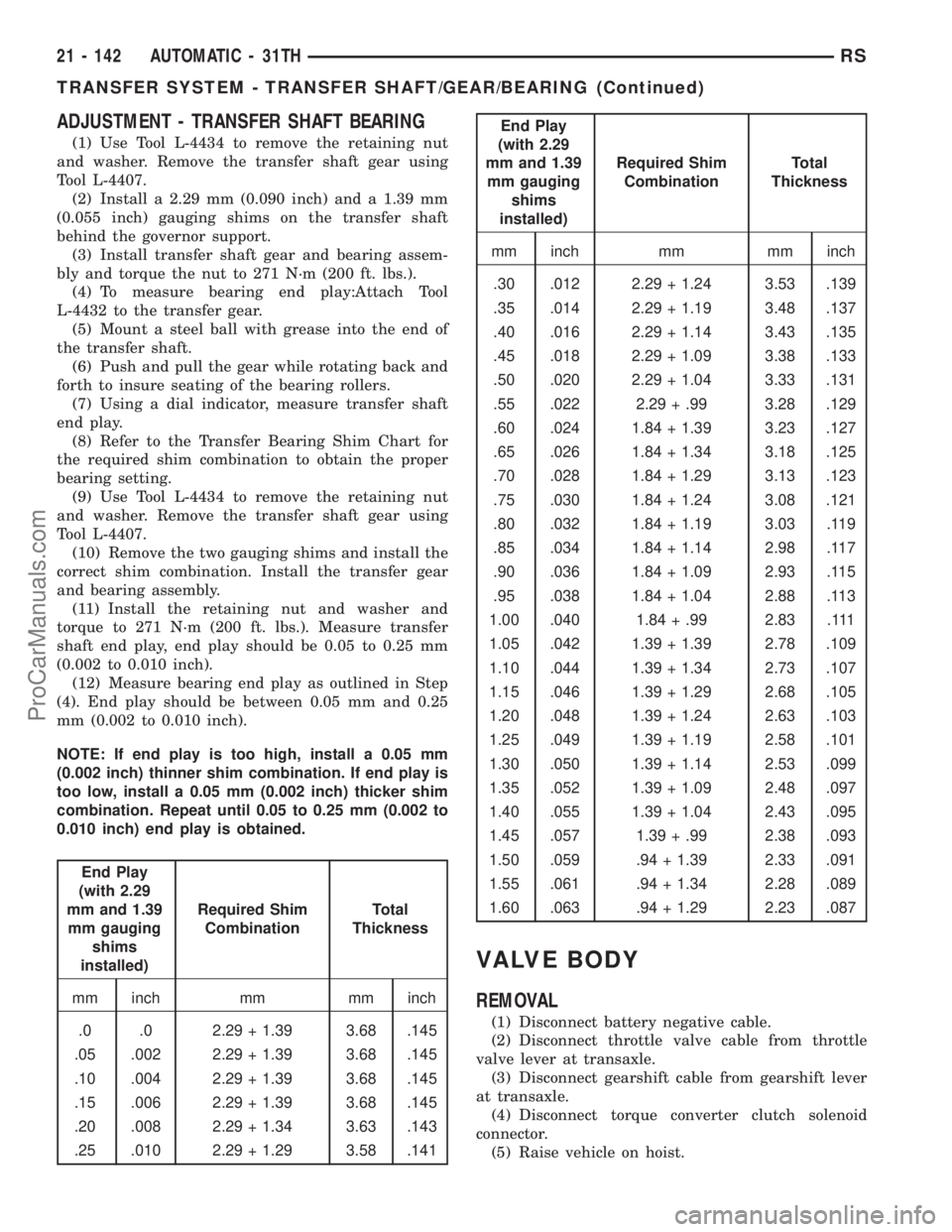
(8) Refer to the Transfer Bearing Shim Chart for
the required shim combination to obtain the proper
bearing setting.
(9) Use Tool L-4434 to remove the retaining nut
and washer. Remove the transfer shaft gear using
Tool L-4407.
(10) Remove the two gauging shims and install the
correct shim combination. Install the transfer gear
and bearing assembly.
(11) Install the retaining nut and washer and
torque to 271 N´m (200 ft. lbs.). Measure transfer
shaft end play, end play should be 0.05 to 0.25 mm
(0.002 to 0.010 inch).
(12) Measure bearing end play as outlined in Step
(4). End play should be between 0.05 mm and 0.25
mm (0.002 to 0.010 inch).
NOTE: If end play is too high, install a 0.05 mm
(0.002 inch) thinner shim combination. If end play is
too low, install a 0.05 mm (0.002 inch) thicker shim
combination. Repeat until 0.05 to 0.25 mm (0.002 to
0.010 inch) end play is obtained.
End Play
(with 2.29
mm and 1.39
mm gauging
shims
installed)Required Shim
CombinationTotal
Thickness
mm inch mm mm inch
.0 .0 2.29 + 1.39 3.68 .145
.05 .002 2.29 + 1.39 3.68 .145
.10 .004 2.29 + 1.39 3.68 .145
.15 .006 2.29 + 1.39 3.68 .145
.20 .008 2.29 + 1.34 3.63 .143
.25 .010 2.29 + 1.29 3.58 .141
End Play
(with 2.29
mm and 1.39
mm gauging
shims
installed)Required Shim
CombinationTotal
Thickness
mm inch mm mm inch
.30 .012 2.29 + 1.24 3.53 .139
.35 .014 2.29 + 1.19 3.48 .137
.40 .016 2.29 + 1.14 3.43 .135
.45 .018 2.29 + 1.09 3.38 .133
.50 .020 2.29 + 1.04 3.33 .131
.55 .022 2.29 + .99 3.28 .129
.60 .024 1.84 + 1.39 3.23 .127
.65 .026 1.84 + 1.34 3.18 .125
.70 .028 1.84 + 1.29 3.13 .123
.75 .030 1.84 + 1.24 3.08 .121
.80 .032 1.84 + 1.19 3.03 .119
.85 .034 1.84 + 1.14 2.98 .117
.90 .036 1.84 + 1.09 2.93 .115
.95 .038 1.84 + 1.04 2.88 .113
1.00 .040 1.84 + .99 2.83 .111
1.05 .042 1.39 + 1.39 2.78 .109
1.10 .044 1.39 + 1.34 2.73 .107
1.15 .046 1.39 + 1.29 2.68 .105
1.20 .048 1.39 + 1.24 2.63 .103
1.25 .049 1.39 + 1.19 2.58 .101
1.30 .050 1.39 + 1.14 2.53 .099
1.35 .052 1.39 + 1.09 2.48 .097
1.40 .055 1.39 + 1.04 2.43 .095
1.45 .057 1.39 + .99 2.38 .093
1.50 .059 .94 + 1.39 2.33 .091
1.55 .061 .94 + 1.34 2.28 .089
1.60 .063 .94 + 1.29 2.23 .087
VALVE BODY
REMOVAL
(1) Disconnect battery negative cable.
(2) Disconnect throttle valve cable from throttle
valve lever at transaxle.
(3) Disconnect gearshift cable from gearshift lever
at transaxle.
(4) Disconnect torque converter clutch solenoid
connector.
(5) Raise vehicle on hoist.
21 - 142 AUTOMATIC - 31THRS
TRANSFER SYSTEM - TRANSFER SHAFT/GEAR/BEARING (Continued)
ProCarManuals.com
Page 1645 of 2321
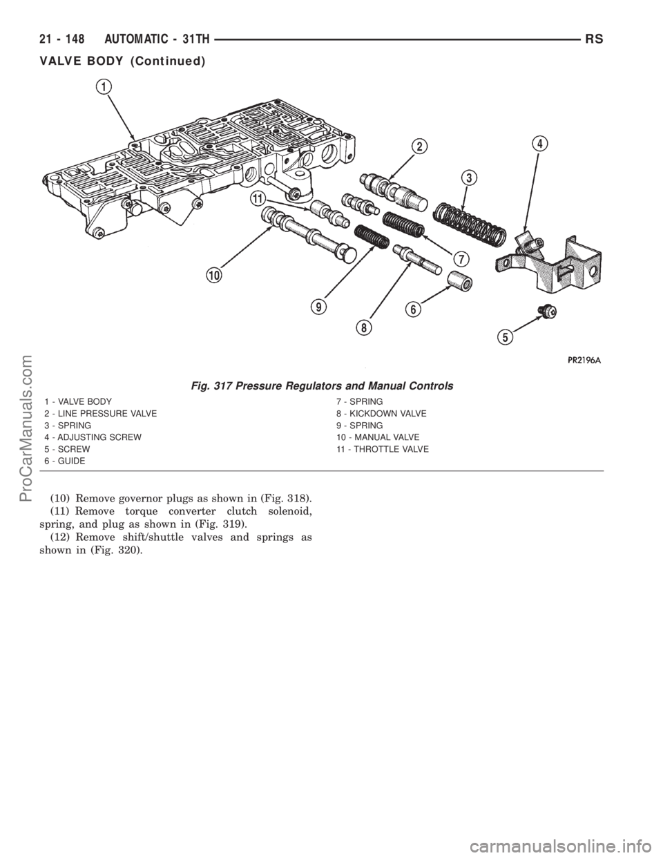
(10) Remove governor plugs as shown in (Fig. 318).
(11) Remove torque converter clutch solenoid,
spring, and plug as shown in (Fig. 319).
(12) Remove shift/shuttle valves and springs as
shown in (Fig. 320).
Fig. 317 Pressure Regulators and Manual Controls
1 - VALVE BODY
2 - LINE PRESSURE VALVE
3 - SPRING
4 - ADJUSTING SCREW
5 - SCREW
6 - GUIDE7 - SPRING
8 - KICKDOWN VALVE
9 - SPRING
10 - MANUAL VALVE
11 - THROTTLE VALVE
21 - 148 AUTOMATIC - 31THRS
VALVE BODY (Continued)
ProCarManuals.com