Page 2305 of 2321

A failed or malfunctioning EGR system can cause
engine spark knock, sags or hesitation, rough idle,
engine stalling and increased emissions.
REMOVAL - 2.4L
The EGR valve and Electrical EGR Transducer are
serviced as an assembly (Fig. 1).(1) Disconnect vacuum tube from electric EGR
transducer. Inspect vacuum tube for damage.
(2) Remove electrical connector from solenoid.
(3) Remove EGR tube bolts from EGR valve.
(4) Remove EGR valve from cylinder head adaptor.
(5) Clean gasket surface and discard old gasket.
Check for any signs of leakage or cracked surfaces.
Repair or replace as necessary.
REMOVAL - 3.3/3.8L
The EGR valve and Electrical EGR Transducer are
serviced as an assembly (Fig. 2).
(1) Disconnect vacuum tube from electric EGR
transducer. Inspect vacuum tube for damage.
(2) Remove electrical connector from solenoid.
(3) Remove EGR tube bolts from EGR valve.
(4) Remove EGR valve from cylinder head adaptor.
(5) Clean gasket surface and discard old gasket.
Check for any signs of leakage or cracked surfaces.
Repair or replace as necessary.
INSTALLATION - 2.4L
The EGR valve and Electrical EGR Transducer are
serviced as an assembly (Fig. 1).
(1) Assemble EGR valve with new gasket onto the
cylinder head adaptor.
(2) Loose assemble the bolts from EGR valve to
EGR tube.
(3) Loose assemble the bolts from EGR valve to
cylinder head.
(4) Tighten bolts from EGR valve to cylinder head
to 22.8 N´m (200625 in. lbs.) torque.
(5) Tighten bolts from EGR valve to EGR tube to
11.9 N´m (105620 in. lbs.) torque.
(6) Reconnect vacuum hose and electrical connec-
tor to electrical EGR transducer.
INSTALLATION - 3.3/3.8L
The EGR valve and Electrical EGR Transducer are
serviced as an assembly (Fig. 2).
(1) Loose assemble the bolts from EGR valve to
EGR tube.
(2) Loose assemble the bolts from EGR valve to
cylinder head adaptor.
(3) Tighten bolts from EGR valve to EGR tube to
11.9 N´m (105620 in. lbs.) torque.
(4) Tighten bolts from EGR valve to cylinder head
to 22.9 N´m (200625 in. lbs.) torque.
(5) Reconnect vacuum hose and electrical connec-
tor to electrical EGR transducer.
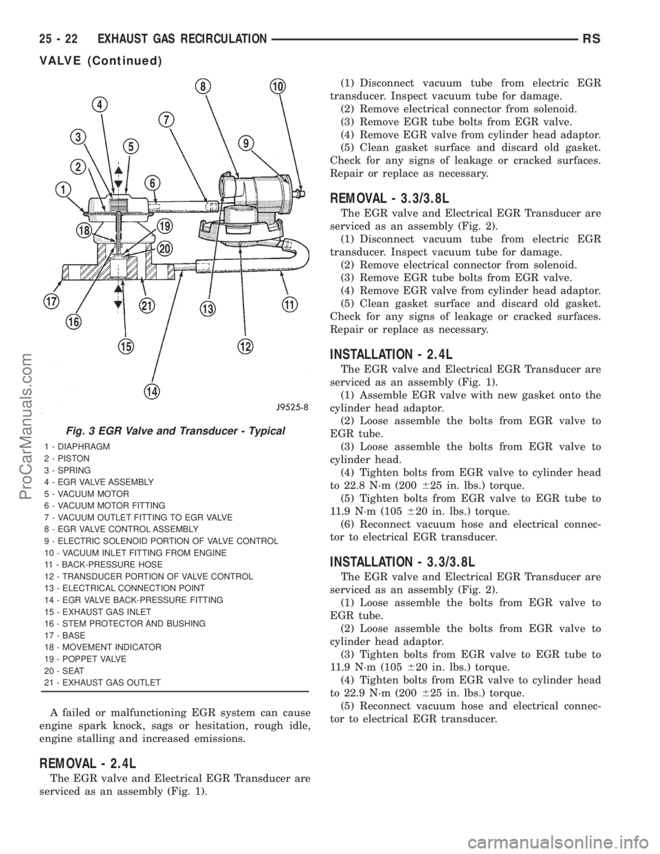
Fig. 3 EGR Valve and Transducer - Typical
1 - DIAPHRAGM
2 - PISTON
3 - SPRING
4 - EGR VALVE ASSEMBLY
5 - VACUUM MOTOR
6 - VACUUM MOTOR FITTING
7 - VACUUM OUTLET FITTING TO EGR VALVE
8 - EGR VALVE CONTROL ASSEMBLY
9 - ELECTRIC SOLENOID PORTION OF VALVE CONTROL
10 - VACUUM INLET FITTING FROM ENGINE
11 - BACK-PRESSURE HOSE
12 - TRANSDUCER PORTION OF VALVE CONTROL
13 - ELECTRICAL CONNECTION POINT
14 - EGR VALVE BACK-PRESSURE FITTING
15 - EXHAUST GAS INLET
16 - STEM PROTECTOR AND BUSHING
17 - BASE
18 - MOVEMENT INDICATOR
19 - POPPET VALVE
20 - SEAT
21 - EXHAUST GAS OUTLET
25 - 22 EXHAUST GAS RECIRCULATIONRS
VALVE (Continued)
ProCarManuals.com
Page 2311 of 2321
SPECIFICATIONS
SPECIFICATIONS - TORQUE
2.5L DIESEL - TORQUE SPECIFICATIONS
DESCRIPTION N´m Ft. Lbs. In. Lbs.
EGR Valve Nuts 32.4 24 Ð
EGR Cooler to EGR Bolts 32.4 24 Ð
25a - 2 EMISSIONS CONTROL 2.5L TURBO DIESELRG
EMISSIONS CONTROL 2.5L TURBO DIESEL (Continued)
ProCarManuals.com
Page 2313 of 2321

OPERATION
The engines use Exhaust Gas Recirculation (EGR)
systems. The EGR system reduces oxides of nitrogen
(NOx) in engine exhaust and helps prevent detona-
tion (engine knock). Under normal operating condi-tions, engine cylinder temperature can reach more
than 3000ÉF. Formation of NOx increases proportion-
ally with combustion temperature. To reduce the
emission of these oxides, the cylinder temperature
must be lowered. The system allows a predetermined
amount of hot exhaust gas to recirculate and dilute
the incoming air/fuel mixture. The diluted air/fuel
mixture reduces peak flame temperature during com-
bustion.
REMOVAL
(1) Remove engine cover (Refer to 9 - ENGINE -
REMOVAL).
(2) Remove front wiper unit (Refer to 8 - ELEC-
TRICAL/WIPERS/WASHERS/WIPER MODULE -
REMOVAL).
(3) Disconnect EGR valve vacuum line.
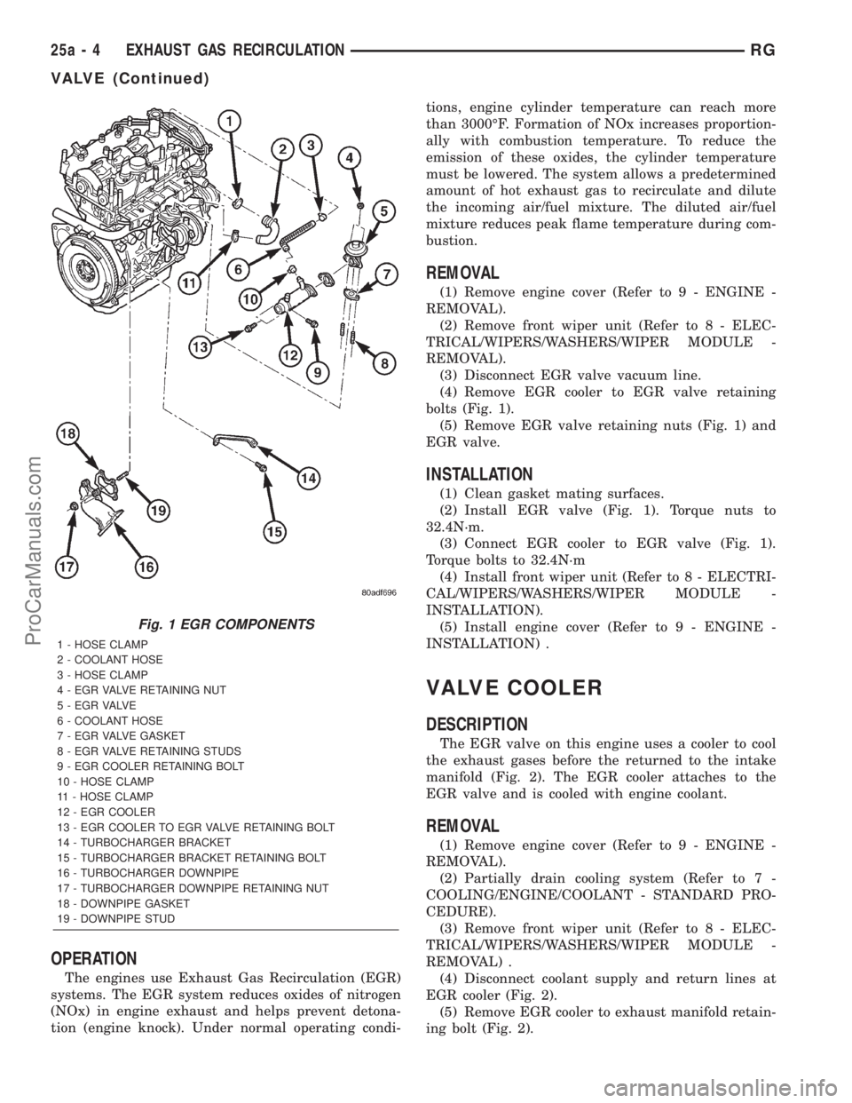
(4) Remove EGR cooler to EGR valve retaining
bolts (Fig. 1).
(5) Remove EGR valve retaining nuts (Fig. 1) and
EGR valve.
INSTALLATION
(1) Clean gasket mating surfaces.
(2) Install EGR valve (Fig. 1). Torque nuts to
32.4N´m.
(3) Connect EGR cooler to EGR valve (Fig. 1).
Torque bolts to 32.4N´m
(4) Install front wiper unit (Refer to 8 - ELECTRI-
CAL/WIPERS/WASHERS/WIPER MODULE -
INSTALLATION).
(5) Install engine cover (Refer to 9 - ENGINE -
INSTALLATION) .
VALVE COOLER
DESCRIPTION
The EGR valve on this engine uses a cooler to cool
the exhaust gases before the returned to the intake
manifold (Fig. 2). The EGR cooler attaches to the
EGR valve and is cooled with engine coolant.
REMOVAL
(1) Remove engine cover (Refer to 9 - ENGINE -
REMOVAL).
(2) Partially drain cooling system (Refer to 7 -
COOLING/ENGINE/COOLANT - STANDARD PRO-
CEDURE).
(3) Remove front wiper unit (Refer to 8 - ELEC-
TRICAL/WIPERS/WASHERS/WIPER MODULE -
REMOVAL) .
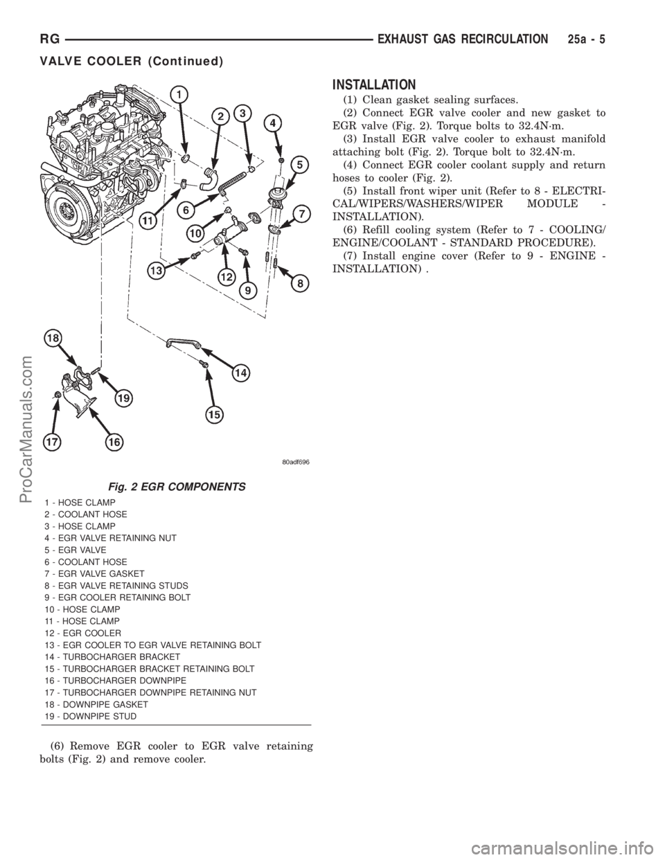
(4) Disconnect coolant supply and return lines at
EGR cooler (Fig. 2).
(5) Remove EGR cooler to exhaust manifold retain-
ing bolt (Fig. 2).
Fig. 1 EGR COMPONENTS
1 - HOSE CLAMP
2 - COOLANT HOSE
3 - HOSE CLAMP
4 - EGR VALVE RETAINING NUT
5 - E G R VA LV E
6 - COOLANT HOSE
7 - EGR VALVE GASKET
8 - EGR VALVE RETAINING STUDS
9 - EGR COOLER RETAINING BOLT
10 - HOSE CLAMP
11 - HOSE CLAMP
12 - EGR COOLER
13 - EGR COOLER TO EGR VALVE RETAINING BOLT
14 - TURBOCHARGER BRACKET
15 - TURBOCHARGER BRACKET RETAINING BOLT
16 - TURBOCHARGER DOWNPIPE
17 - TURBOCHARGER DOWNPIPE RETAINING NUT
18 - DOWNPIPE GASKET
19 - DOWNPIPE STUD
25a - 4 EXHAUST GAS RECIRCULATIONRG
VALVE (Continued)
ProCarManuals.com
Page 2314 of 2321

(6) Remove EGR cooler to EGR valve retaining
bolts (Fig. 2) and remove cooler.
INSTALLATION
(1) Clean gasket sealing surfaces.
(2) Connect EGR valve cooler and new gasket to
EGR valve (Fig. 2). Torque bolts to 32.4N´m.
(3) Install EGR valve cooler to exhaust manifold
attaching bolt (Fig. 2). Torque bolt to 32.4N´m.
(4) Connect EGR cooler coolant supply and return
hoses to cooler (Fig. 2).
(5) Install front wiper unit (Refer to 8 - ELECTRI-
CAL/WIPERS/WASHERS/WIPER MODULE -
INSTALLATION).
(6) Refill cooling system (Refer to 7 - COOLING/
ENGINE/COOLANT - STANDARD PROCEDURE).
(7) Install engine cover (Refer to 9 - ENGINE -
INSTALLATION) .
Fig. 2 EGR COMPONENTS
1 - HOSE CLAMP
2 - COOLANT HOSE
3 - HOSE CLAMP
4 - EGR VALVE RETAINING NUT
5 - E G R VA LV E
6 - COOLANT HOSE
7 - EGR VALVE GASKET
8 - EGR VALVE RETAINING STUDS
9 - EGR COOLER RETAINING BOLT
10 - HOSE CLAMP
11 - HOSE CLAMP
12 - EGR COOLER
13 - EGR COOLER TO EGR VALVE RETAINING BOLT
14 - TURBOCHARGER BRACKET
15 - TURBOCHARGER BRACKET RETAINING BOLT
16 - TURBOCHARGER DOWNPIPE
17 - TURBOCHARGER DOWNPIPE RETAINING NUT
18 - DOWNPIPE GASKET
19 - DOWNPIPE STUD
RGEXHAUST GAS RECIRCULATION25a-5
VALVE COOLER (Continued)
ProCarManuals.com