Page 1559 of 2321
(19) Connect throttle valve cable to lever and
bracket (Fig. 103).
(20) Connect torque converter clutch connector.(21) Install fluid level indicator/tube assembly
(Fig. 104).
(22) Raise vehicle on hoist.
(23) Torque rear mount bracket-to-transaxle case
horizontal bolt (Fig. 98) to 102 N´m (75 ft. lbs.).
(24) Torque rear mount thru-bolt to 54 N´m (40 ft.
lbs.).
(25) Lower vehicle.
(26) Connect battery negative cable.
(27) Fill transaxle with ATF+4 transmission fluid.
(Refer to 21 - TRANSMISSION/TRANSAXLE/AUTO-
MATIC - 31TH/FLUID - STANDARD PROCEDURE)
Fig. 103 Kickdown Cable at TransaxleÐTypical
1 - LEVER
2 - BRACKET
3 - THROTTLE VALVE CABLE
Fig. 104 Fluid Level Indicator Assembly
1 - INDICATOR ASSEMBLY
2 - BOLT
3 - KICKDOWN CABLE BRACKET
4 - SEAL
21 - 62 AUTOMATIC - 31THRS
AUTOMATIC - 31TH (Continued)
ProCarManuals.com
Page 1568 of 2321
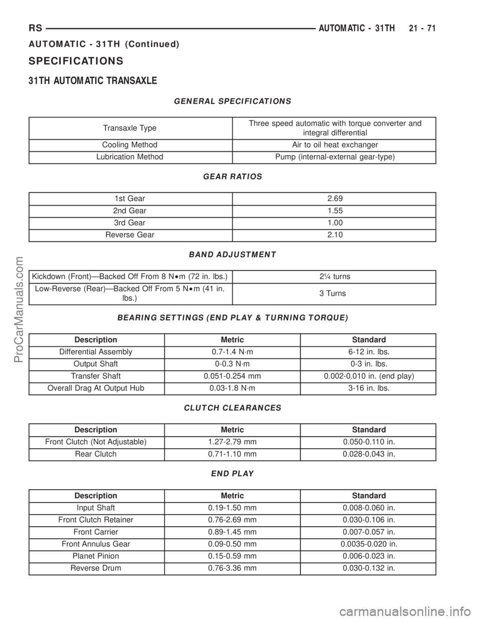
SPECIFICATIONS
31TH AUTOMATIC TRANSAXLE
GENERAL SPECIFICATIONS
Transaxle TypeThree speed automatic with torque converter and
integral differential
Cooling Method Air to oil heat exchanger
Lubrication Method Pump (internal-external gear-type)
GEAR RATIOS
1st Gear 2.69
2nd Gear 1.55
3rd Gear 1.00
Reverse Gear 2.10
BAND ADJUSTMENT
Kickdown (Front)ÐBacked Off From 8 N²m (72 in. lbs.) 2ò turns
Low-Reverse (Rear)ÐBacked Off From 5 N²m (41 in.
lbs.)3 Turns
BEARING SETTINGS (END PLAY & TURNING TORQUE)
Description Metric Standard
Differential Assembly 0.7-1.4 N´m 6-12 in. lbs.
Output Shaft 0-0.3 N´m 0-3 in. lbs.
Transfer Shaft 0.051-0.254 mm 0.002-0.010 in. (end play)
Overall Drag At Output Hub 0.03-1.8 N´m 3-16 in. lbs.
CLUTCH CLEARANCES
Description Metric Standard
Front Clutch (Not Adjustable) 1.27-2.79 mm 0.050-0.110 in.
Rear Clutch 0.71-1.10 mm 0.028-0.043 in.
END PLAY
Description Metric Standard
Input Shaft 0.19-1.50 mm 0.008-0.060 in.
Front Clutch Retainer 0.76-2.69 mm 0.030-0.106 in.
Front Carrier 0.89-1.45 mm 0.007-0.057 in.
Front Annulus Gear 0.09-0.50 mm 0.0035-0.020 in.
Planet Pinion 0.15-0.59 mm 0.006-0.023 in.
Reverse Drum 0.76-3.36 mm 0.030-0.132 in.
RSAUTOMATIC - 31TH21-71
AUTOMATIC - 31TH (Continued)
ProCarManuals.com
Page 1569 of 2321
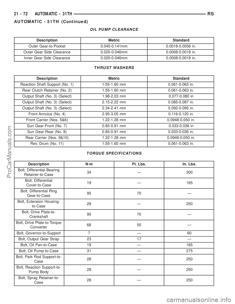
OIL PUMP CLEARANCE
Description Metric Standard
Outer Gear-to-Pocket 0.045-0.141mm 0.0018-0.0056 in.
Outer Gear Side Clearance 0.020-0.046mm 0.0008-0.0018 in.
Inner Gear Side Clearance 0.020-0.046mm 0.0008-0.0018 in.
THRUST WASHERS
Description Metric Standard
Reaction Shaft Support (No. 1) 1.55-1.60 mm 0.061-0.063 in.
Rear Clutch Retainer (No. 2) 1.55-1.60 mm 0.061-0.063 in.
Output Shaft (No. 3) (Select) 1.98-2.03 mm 0.077-0.080 in
Output Shaft (No. 3) (Select) 2.15-2.22 mm 0.085-0.087 in.
Output Shaft (No. 3) (Select) 2.34-2.41 mm 0.092-0.095 in.
Front Annulus (No. 4) 2.95-3.05 mm 0.116-0.120 in.
Front Carrier (Nos. 5&6) 1.22-1.28 mm 0.0948-0.050 in.
Sun Gear-Front (No. 7) 0.85-0.91 mm 0.033-0.036 in
Sun Gear-Rear (No. 8) 0.85-0.91 mm 0.033-0.036 in.
Rear Carrier (Nos. 9&10) 1.22-1.28 mm 0.0948-0.050 in.
Rev. Drum (No. 11) 1.55-1.60 mm 0.061-0.063 in.
TORQUE SPECIFICATIONS
Description N´m Ft. Lbs. In. Lbs.
Bolt, Differential Bearing
Retainer-to-Case34 Ð 300
Bolt, Differential
Cover-to-Case19 Ð 165
Bolt, Differential Ring
Gear-to-Case95 70 Ð
Bolt, Extension Housing-
to-Case28 Ð 250
Bolt, Drive Plate-to-
Crankshaft95 70 Ð
Bolt, Drive Plate-to-Torque
Converter68 50 Ð
Bolt, Governor-to-Support 7 Ð 60
Bolt, Output Gear Strap 23 17 Ð
Bolt, Oil Pan-to-Case 19 Ð 165
Bolt, Oil Pump-to-Case 31 Ð 275
Bolt, Park Rod Support-to-
Case28 Ð 250
Bolt, Reaction Support-to-
Pump Body28 Ð 250
Bolt, Sprag Retainer-to-
Case28 Ð 250
21 - 72 AUTOMATIC - 31THRS
AUTOMATIC - 31TH (Continued)
ProCarManuals.com
Page 1572 of 2321
Universal Handle C-4171
Seal Installer C-4193A
Bearing Installer C-4637
Adapter C-4658
Torque Tool C-4995
Adapter C-4996
Remover Kit L-4406
Bearing Remover Cup L-4406±1
Bearing Remover Jaws L-4406±2
RSAUTOMATIC - 31TH21-75
AUTOMATIC - 31TH (Continued)
ProCarManuals.com
Page 1577 of 2321
(5) Back off front band adjusting screw 2ò turns.
(6) Hold adjuster screw in position and tighten
locknut to 47 N´m (35 ft. lbs.) torque.
(7) Install air cleaner assembly.
(8) Connect battery negative cable.
ADJUSTMENTS - REAR BAND
The transmission oil pan must be removed for
access to the rear (low/reverse) band adjusting screw.
(1) Raise vehicle.
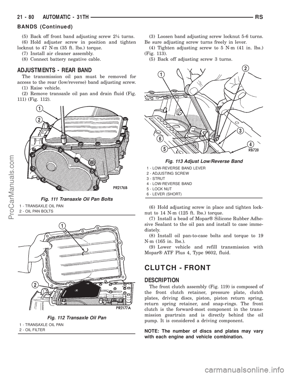
(2) Remove transaxle oil pan and drain fluid (Fig.
111) (Fig. 112).(3) Loosen band adjusting screw locknut 5-6 turns.
Be sure adjusting screw turns freely in lever.
(4) Tighten adjusting screw to 5 N´m (41 in. lbs.)
(Fig. 113).
(5) Back off adjusting screw 3 turns.
(6) Hold adjusting screw in place and tighten lock-
nut to 14 N´m (125 ft. lbs.) torque.
(7) Install a bead of Moparž Silicone Rubber Adhe-
sive Sealant to the oil pan and install to case imme-
diately.
(8) Install oil pan-to-case bolts and torque to 19
N´m (165 in. lbs.).
(9) Lower vehicle and refill transmission with
Moparž ATF Plus 4, Type 9602, fluid.
CLUTCH - FRONT
DESCRIPTION
The front clutch assembly (Fig. 119) is composed of
the front clutch retainer, pressure plate, clutch
plates, driving discs, piston, piston return spring,
return spring retainer, and snap-rings. The front
clutch is the forward-most component in the trans-
mission geartrain and is directly behind the oil
pump. It is considered a driving component.
NOTE: The number of discs and plates may vary
with each engine and vehicle combination.
Fig. 111 Transaxle Oil Pan Bolts
1 - TRANSAXLE OIL PAN
2 - OIL PAN BOLTS
Fig. 112 Transaxle Oil Pan
1 - TRANSAXLE OIL PAN
2 - OIL FILTER
Fig. 113 Adjust Low/Reverse Band
1 - LOW-REVERSE BAND LEVER
2 - ADJUSTING SCREW
3 - STRUT
4 - LOW-REVERSE BAND
5 - LOCK NUT
6 - LEVER (SHORT)
21 - 80 AUTOMATIC - 31THRS
BANDS (Continued)
ProCarManuals.com
Page 1578 of 2321
OPERATION
To apply the clutch, pressure is applied between
the clutch retainer and piston. The fluid pressure is
provided by the oil pump, transferred through the
control valves and passageways, and enters the
clutch through the hub of the reaction shaft support.
With pressure applied between the clutch retainer
and piston, the piston moves away from the clutch
retainer and compresses the clutch pack. This action
applies the clutch pack, allowing torque to flow
through the input shaft into the driving discs, and
into the clutch plates and pressure plate that are
lugged to the clutch retainer. The waved snap-ring is
used to cushion the application of the clutch pack. In
some transmissions, the snap-ring is selective and
used to adjust clutch pack clearance.
When pressure is released from the piston, the
spring returns the piston to its fully released position
and disengages the clutch. The release spring also
helps to cushion the application of the clutch assem-
bly. When the clutch is in the process of being
released by the release spring, fluid flows through a
vent and one-way ball-check-valve located in the
clutch retainer. The check-valve is needed to elimi-
nate the possibility of plate drag caused by centrifu-
gal force acting on the residual fluid trapped in the
clutch piston retainer.
DISASSEMBLY
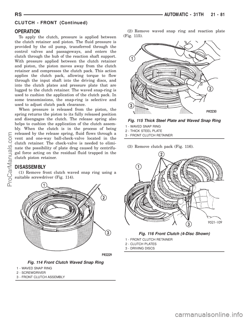
(1) Remove front clutch waved snap ring using a
suitable screwdriver (Fig. 114).(2) Remove waved snap ring and reaction plate
(Fig. 115).
(3) Remove clutch pack (Fig. 116).
Fig. 114 Front Clutch Waved Snap Ring
1 - WAVED SNAP RING
2 - SCREWDRIVER
3 - FRONT CLUTCH ASSEMBLY
Fig. 115 Thick Steel Plate and Waved Snap Ring
1 - WAVED SNAP RING
2 - THICK STEEL PLATE
3 - FRONT CLUTCH RETAINER
Fig. 116 Front Clutch (4-Disc Shown)
1 - FRONT CLUTCH RETAINER
2 - CLUTCH PLATES
3 - DRIVING DISCS
RSAUTOMATIC - 31TH21-81
CLUTCH - FRONT (Continued)
ProCarManuals.com
Page 1582 of 2321
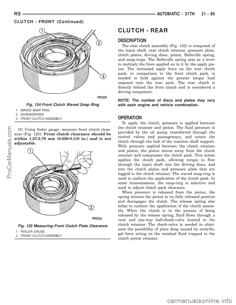
(5) Using feeler gauge, measure front clutch clear-
ance (Fig. 125).Front clutch clearance should be
within 1.27-2.79 mm (0.050-0.110 in.) and is not
adjustable.
CLUTCH - REAR
DESCRIPTION
The rear clutch assembly (Fig. 132) is composed of
the input shaft, rear clutch retainer, pressure plate,
clutch plates, driving discs, piston, Belleville spring,
and snap-rings. The Belleville spring acts as a lever
to multiply the force applied on to it by the apply pis-
ton. The increased apply force on the rear clutch
pack, in comparison to the front clutch pack, is
needed to hold against the greater torque load
imposed onto the rear pack. The rear clutch is
directly behind the front clutch and is considered a
driving component.
NOTE: The number of discs and plates may vary
with each engine and vehicle combination.
OPERATION
To apply the clutch, pressure is applied between
the clutch retainer and piston. The fluid pressure is
provided by the oil pump, transferred through the
control valves and passageways, and enters the
clutch through the hub of the reaction shaft support.
With pressure applied between the clutch retainer
and piston, the piston moves away from the clutch
retainer and compresses the clutch pack. This action
applies the clutch pack, allowing torque to flow
through the input shaft into the driving discs, and
into the clutch plates and pressure plate that are
lugged to the clutch retainer. The waved snap-ring is
used to cushion the application of the clutch pack. In
some transmissions, the snap-ring is selective and
used to adjust clutch pack clearance.
When pressure is released from the piston, the
spring returns the piston to its fully released position
and disengages the clutch. The release spring also
helps to cushion the application of the clutch assem-
bly. When the clutch is in the process of being
released by the release spring, fluid flows through a
vent and one-way ball-check-valve located in the
clutch retainer. The check-valve is needed to elimi-
nate the possibility of plate drag caused by centrifu-
gal force acting on the residual fluid trapped in the
clutch piston retainer.
Fig. 124 Front Clutch Waved Snap Ring
1 - WAVED SNAP RING
2 - SCREWDRIVER
3 - FRONT CLUTCH ASSEMBLY
Fig. 125 Measuring Front Clutch Plate Clearance
1 - FEELER GAUGE
2 - FRONT CLUTCH ASSEMBLY
RSAUTOMATIC - 31TH21-85
CLUTCH - FRONT (Continued)
ProCarManuals.com
Page 1587 of 2321
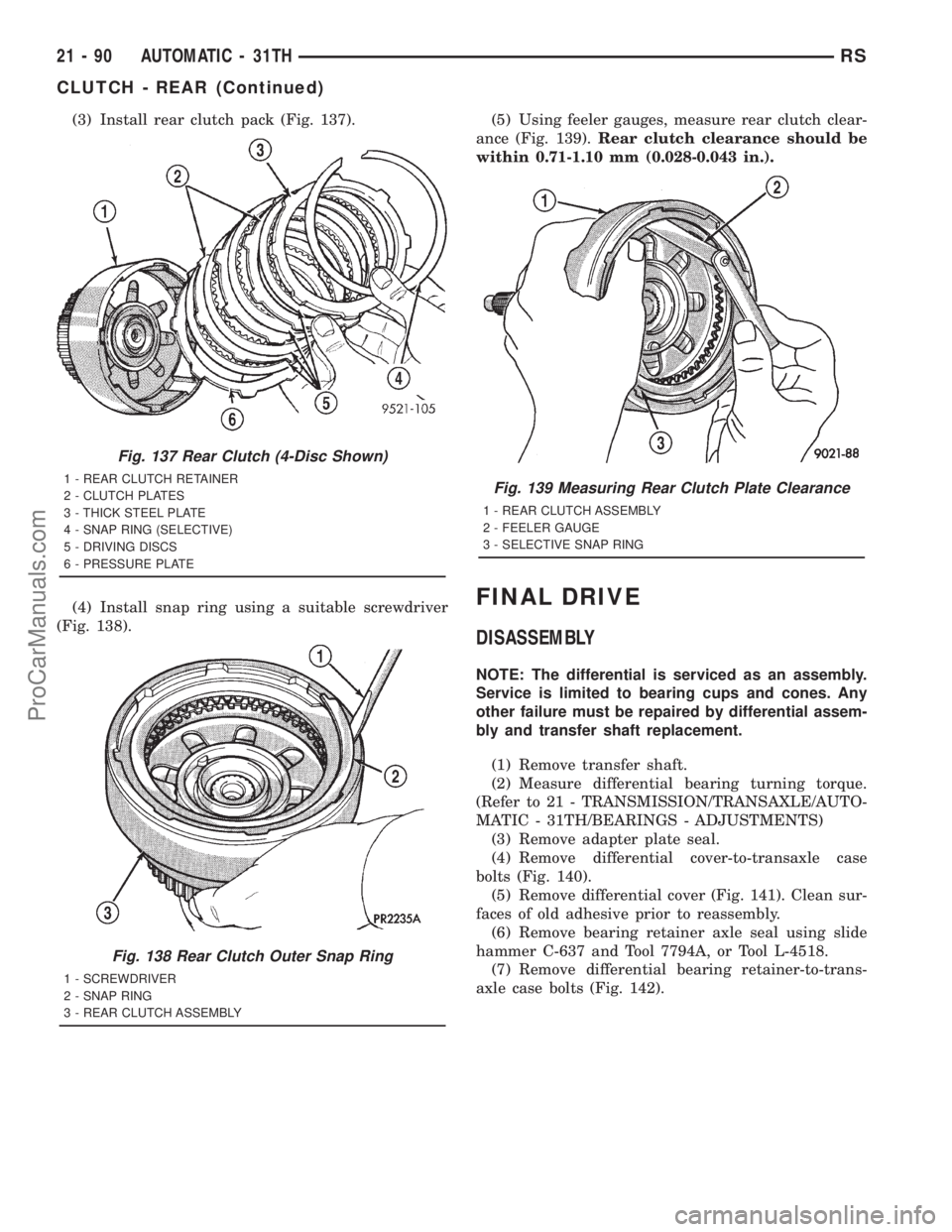
(3) Install rear clutch pack (Fig. 137).
(4) Install snap ring using a suitable screwdriver
(Fig. 138).(5) Using feeler gauges, measure rear clutch clear-
ance (Fig. 139).Rear clutch clearance should be
within 0.71-1.10 mm (0.028-0.043 in.).
FINAL DRIVE
DISASSEMBLY
NOTE: The differential is serviced as an assembly.
Service is limited to bearing cups and cones. Any
other failure must be repaired by differential assem-
bly and transfer shaft replacement.
(1) Remove transfer shaft.
(2) Measure differential bearing turning torque.
(Refer to 21 - TRANSMISSION/TRANSAXLE/AUTO-
MATIC - 31TH/BEARINGS - ADJUSTMENTS)
(3) Remove adapter plate seal.
(4) Remove differential cover-to-transaxle case
bolts (Fig. 140).
(5) Remove differential cover (Fig. 141). Clean sur-
faces of old adhesive prior to reassembly.
(6) Remove bearing retainer axle seal using slide
hammer C-637 and Tool 7794A, or Tool L-4518.
(7) Remove differential bearing retainer-to-trans-
axle case bolts (Fig. 142).
Fig. 137 Rear Clutch (4-Disc Shown)
1 - REAR CLUTCH RETAINER
2 - CLUTCH PLATES
3 - THICK STEEL PLATE
4 - SNAP RING (SELECTIVE)
5 - DRIVING DISCS
6 - PRESSURE PLATE
Fig. 138 Rear Clutch Outer Snap Ring
1 - SCREWDRIVER
2 - SNAP RING
3 - REAR CLUTCH ASSEMBLY
Fig. 139 Measuring Rear Clutch Plate Clearance
1 - REAR CLUTCH ASSEMBLY
2 - FEELER GAUGE
3 - SELECTIVE SNAP RING
21 - 90 AUTOMATIC - 31THRS
CLUTCH - REAR (Continued)
ProCarManuals.com