2001 DODGE TOWN AND COUNTRY drain bolt
[x] Cancel search: drain boltPage 138 of 2321
DIAGNOSIS AND TESTING - REAR DRIVELINE
MODULE OPERATION
Driveline module operation requires relatively
straight-forward diagnosis. Refer to the following
chart:
DRIVELINE MODULE DIAGNOSIS CHART
CONDITION POSSIBLE CAUSES CORRECTION
Rear wheels not
overrunning1) Bi-directional overrunning clutch
failure1) Replace overrunning clutch
components as required
No AWD in forward or
reverse directions, propeller
shaft turning1) Bi-directional overrunning clutch
failure1) Replace overrunning clutch
components as required
2) Viscous coupling failure 2) Replace viscous coupling
3) Rear differential failure 3) Replace the rear differential
assembly
No AWD in forward or
reverse directions, propeller
shaft not turning1) Power transfer unit failure. 1) Replace power transfer unit
components as necessary
Vibration at all speeds,
continuous torque transfer1) Mis-matched tires, worn tires on
front axle.1) Replace worn or incorrect
(mis-matched) tires with same
make and size
REMOVAL
(1) Raise vehicle on hoist.
(2) Drain fluid from overrunning clutch housing
and/or differential assembly if necessary.
(3) Remove propeller shaft. (Refer to 3 - DIFFER-
ENTIAL & DRIVELINE/PROPELLER SHAFT -
REMOVAL)
(4) Disconnect left and right rear halfshafts from
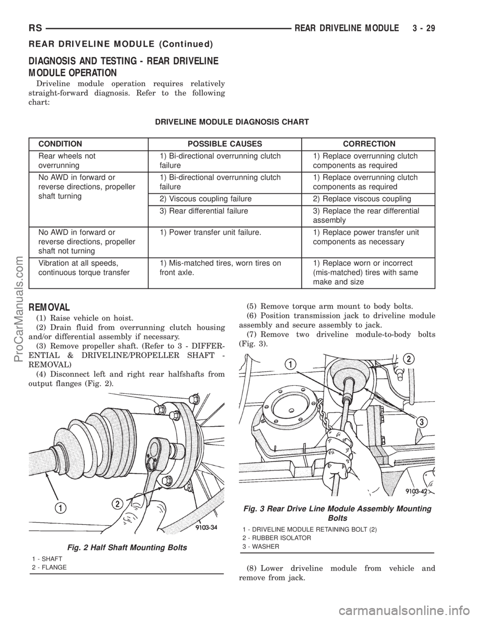
output flanges (Fig. 2).(5) Remove torque arm mount to body bolts.
(6) Position transmission jack to driveline module
assembly and secure assembly to jack.
(7) Remove two driveline module-to-body bolts
(Fig. 3).
(8) Lower driveline module from vehicle and
remove from jack.
Fig. 2 Half Shaft Mounting Bolts
1 - SHAFT
2 - FLANGE
Fig. 3 Rear Drive Line Module Assembly Mounting
Bolts
1 - DRIVELINE MODULE RETAINING BOLT (2)
2 - RUBBER ISOLATOR
3 - WASHER
RSREAR DRIVELINE MODULE3-29
REAR DRIVELINE MODULE (Continued)
ProCarManuals.com
Page 146 of 2321
SPECIFICATIONS
SPECIFICATIONS - REAR DRIVELINE MODULE
TORQUE SPECIFICATIONS
DESCRIPTION N´m Ft. Lbs. In. Lbs.
Bolt, Driveline Module-to-Body 54 40 Ð
Bolt, Halfshaft-to-Ouput Flange 61 45 Ð
Bolt, Overrunning Clutch Housing-to-
Differential60 44 Ð
Bolt, Torque Arm-to-Differential Assembly 60 44 Ð
Bolt, Torque Arm Mount-to-Body 54 40 Ð
Nut, Input Flange 135 100 Ð
Plug, Differential Drain/Fill 35 26 Ð
Plug, Overrunning Clutch Housing Drain/Fill 30 22 Ð
Vent, Differential/Overrunning Clutch
Housing12 Ð 110
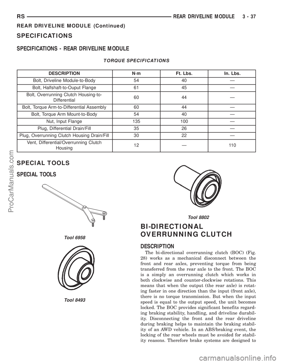
SPECIAL TOOLS
SPECIAL TOOLS
BI-DIRECTIONAL
OVERRUNNING CLUTCH
DESCRIPTION
The bi-directional overrunning clutch (BOC) (Fig.
28) works as a mechanical disconnect between the
front and rear axles, preventing torque from being
transferred from the rear axle to the front. The BOC
is a simply an overrunning clutch which works in
both clockwise and counter-clockwise rotations. This
means that when the output (the rear axle) is rotat-
ing faster in one direction than the input (front axle),
there is no torque transmission. But when the input
speed is equal to the output speed, the unit becomes
locked. The BOC provides significant benefits regard-
ing braking stability, handling, and driveline durabil-
ity. Disconnecting the front and the rear driveline
during braking helps to maintain the braking stabil-
ity of an AWD vehicle. In an ABS/braking event, the
locking of the rear wheels must be avoided for stabil-
ity reasons. Therefore brake systems are designed to
Tool 6958
Tool 8493
Tool 8802
RSREAR DRIVELINE MODULE3-37
REAR DRIVELINE MODULE (Continued)
ProCarManuals.com
Page 181 of 2321
(20) Road test vehicle. The automatic adjuster will
continue the brake adjustment during the road test
of the vehicle.
ADJUSTMENT - REAR DRUM BRAKE SHOES
NOTE: Normally, self-adjusting drum brakes do not
require manual brake shoe adjustment. Although, in
the event of a brake shoe replacement, it is advis-
able to make the initial adjustment manually to
speed up the adjusting time.
NOTE: Before raising the vehicle, verify the parking
brake lever is fully released.
(1) Raise the vehicle. (Refer to LUBRICATION &
MAINTENANCE/HOISTING - STANDARD PROCE-
DURE).
(2) Remove rubber plug from rear brake adjusting
hole in the rear brake support plate.
(3) Insert a thin screwdriver through the adjusting
hole in the support plate and against the star wheel
of the adjusting screw. Move handle of the tool
upward rotating the star wheel until a slight drag is
felt when tire and wheel assembly is rotated.
(4) Insert a second thin screwdriver or piece of
welding rod into brake adjusting hole and push the
adjusting lever out of engagement with the star
wheel.Care should be taken so as not to bend
adjusting lever or distort lever spring.
(5) While holding the adjusting lever out of
engagement, back off the star wheel just enough to
ensure a free wheel with no brake shoe drag.
(6) Repeat the above adjustment at the other rear
wheel.
(7) Install the adjusting hole rubber plugs back in
the rear brake support plates.
(8) Lower the vehicle.
DISC BRAKE CALIPERS -
FRONT
REMOVAL - FRONT DISC BRAKE CALIPER
(DISC/DISC BRAKES)
(1) Depress the brake pedal past its first inch of
travel and hold it in this position using a brake pedal
depressor (holding) tool. This is done to isolate the
master cylinder from the brake hydraulic system dis-
allowing the brake fluid to completely drain out of
the brake fluid reservoir.
(2) Raise the vehicle. (Refer to LUBRICATION &
MAINTENANCE/HOISTING - STANDARD PROCE-
DURE).
(3) Remove front wheel and tire assembly.(4) Remove the banjo bolt connecting the brake
hose to the brake caliper. There are two washers (one
on each side of the brake hose fitting) that will come
off with the banjo bolt. Discard these washers.
(5) Remove the 2 caliper guide pin bolts.
(6) Remove the brake caliper from the adapter.
REMOVAL - FRONT DISC BRAKE CALIPER
(DISC/DRUM BRAKES)
(1) Using a brake pedal holding tool, depress the
brake pedal past its first one inch of travel and hold
it in this position. This will isolate the master cylin-
der from the brake hydraulic system and will not
allow the brake fluid to drain out of the master cyl-
inder reservoir when the lines are opened.
(2) Raise the vehicle. Refer to HOISTING in
LUBRICATION AND MAINTENANCE.
(3) Remove the front tire and wheel assembly.
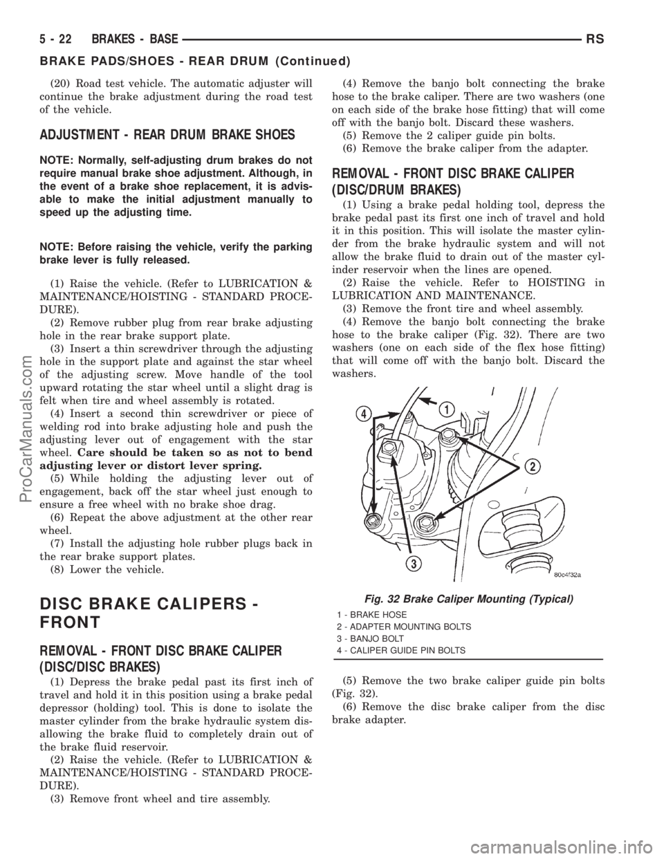
(4) Remove the banjo bolt connecting the brake
hose to the brake caliper (Fig. 32). There are two
washers (one on each side of the flex hose fitting)
that will come off with the banjo bolt. Discard the
washers.
(5) Remove the two brake caliper guide pin bolts
(Fig. 32).
(6) Remove the disc brake caliper from the disc
brake adapter.
Fig. 32 Brake Caliper Mounting (Typical)
1 - BRAKE HOSE
2 - ADAPTER MOUNTING BOLTS
3 - BANJO BOLT
4 - CALIPER GUIDE PIN BOLTS
5 - 22 BRAKES - BASERS
BRAKE PADS/SHOES - REAR DRUM (Continued)
ProCarManuals.com
Page 185 of 2321
(10) Road test the vehicle and make several stops
to wear off any foreign material on the brakes and to
seat the brake shoe linings.
INSTALLATION - FRONT DISC BRAKE CALIPER
(DISC/DRUM BRAKES)
CAUTION: TRW and Continental Teves brake cali-
pers are not interchangeable. Each caliper is specif-
ically designed for the unique brake system (TRW -
disc/drum brake combination and Continental Teves
- disc/disc brake combination). If calipers are inter-
changed, improper performance, noise and
increased stopping distance can occur.
(1) Completely retract the caliper piston back into
the bore of the caliper. Use a C-clamp to retract the
piston if necessary. Place a wood block over the pis-
ton before installing the C-clamp to avoid damaging
the piston.
CAUTION: Use care when installing the caliper onto
the disc brake adapter to avoid damaging the boots
on the caliper guide pins.
(2) Install the disc brake caliper over the brake
shoes on the brake caliper adapter.
(3) Align the caliper guide pin bolt holes with the
guide pins. Install the caliper guide pin bolts and
tighten them to a torque of 35 N´m (26 ft. lbs.) (Fig.
32).
(4) Install the banjo bolt connecting the brake hose
to the brake caliper (Fig. 32). Install NEW copper
washers on each side of the hose fitting as the banjo
bolt is guided through the fitting. Thread the banjo
bolt into the caliper and tighten it to a torque of 47
N´m (35 ft. lbs.).
(5) Install the tire and wheel assembly. Tighten
the wheel mounting nuts to a torque of 135 N´m (100
ft. lbs.).
(6) Lower the vehicle.
(7) Remove the brake pedal holding tool.
(8) Bleed the caliper as necessary. (Refer to 5 -
BRAKES - BASE - STANDARD PROCEDURE).
(9) Road test the vehicle and make several stops to
wear off any foreign material on the brakes and to
seat the brake shoes.
DISC BRAKE CALIPERS -
REAR
REMOVAL - REAR DISC BRAKE CALIPER
NOTE: Handling of the rotor and caliper, must be
done in such a way as to avoid damage to the rotorand scratching or nicking of lining on the brake
shoes.
(1) Depress the brake pedal past its first inch of
travel and hold it in this position using a brake pedal
depressor (holding) tool. This is done to isolate the
master cylinder from the brake hydraulic system dis-
allowing the brake fluid to completely drain out of
the brake fluid reservoir.
(2) Raise the vehicle. (Refer to LUBRICATION &
MAINTENANCE/HOISTING - STANDARD PROCE-
DURE)
(3) Remove rear wheel and tire assembly from
vehicle.
(4) Remove the banjo bolt connecting the brake
hose to the brake caliper. There are two washers (one
on each side of the brake hose fitting) that will come
off with the banjo bolt. Discard these washers.
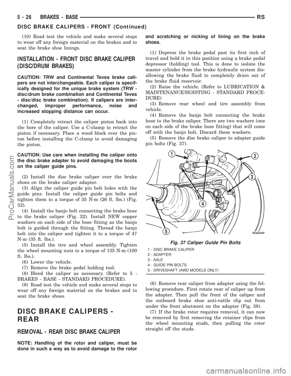
(5) Remove the disc brake caliper to adapter guide
pin bolts (Fig. 37).
(6) Remove rear caliper from adapter using the fol-
lowing procedure. First rotate rear of caliper up from
the adapter. Then pull the front of the caliper and
the outboard brake shoe anti-rattle clip out from
under the front abutment on the adapter (Fig. 38).
(7) If the brake rotor requires removal, it can now
be removed by first removing the retainer clips from
the wheel mounting studs, then pulling the rotor
straight off the studs.
Fig. 37 Caliper Guide Pin Bolts
1 - DISC BRAKE CALIPER
2 - ADAPTER
3 - AXLE
4 - GUIDE PIN BOLTS
5 - DRIVESHAFT (AWD MODELS ONLY)
5 - 26 BRAKES - BASERS
DISC BRAKE CALIPERS - FRONT (Continued)
ProCarManuals.com
Page 202 of 2321
(2) Raise vehicle. (Refer to LUBRICATION &
MAINTENANCE/HOISTING - STANDARD PROCE-
DURE)
(3) Remove the chassis brake tube going to the
rear brake in question at the proportioning valve.
Remove the chassis brake tube coming from the junc-
tion block at the proportioning valve (Fig. 62).
(4) Install the appropriate fittings from Pressure
Test Fittings, Special Tool 6833, into the open ports
of the proportioning valve.
(5) Install the previously removed brake lines into
the Pressure Test Fittings. Tighten all tube nuts to
17 N´m (145 in. lbs.).
(6) Install a pressure gauge from Gauge Set, Spe-
cial Tool C-4007-A into the open port on each pres-
sure test fitting. Bleed air out of hose from pressure
test fittings to pressure gauges at the pressure
gauges. Then bleed air out of the brake line being
tested at that rear wheel brake bleeder.
(7) Remove the screw fastening the proportioning
valve actuator lever bracket to the rear axle. Raise
the actuator lever to the full-upward position.
(8) With the aid of a helper, apply pressure to the
brake pedal until a pressure of 6895 kPa (1000 psi) is
obtained on the proportioning valve inlet gauge.
Then, based on the type of brake system the vehicleis equipped with and the pressure specification
shown on the following table, compare the pressure
reading on the outlet gauge to the specification. If
outlet pressure at the proportioning valve is not
within specification when required inlet pressure is
obtained, replace the proportioning valve. (Refer to 5
- BRAKES/HYDRAULIC/MECHANICAL/PROPOR-
TIONING VALVE - REMOVAL)
CAUTION: Do not attempt to adjust the height sens-
ing proportioning valve. If found to be defective,
replace the valve.
(9) Remove the pressure test fittings and pressure
gauges from the proportioning valve.
(10) Install the chassis brake lines in the correct
ports of the proportioning valve. Tighten all tube
nuts to 17 N´m (145 in. lbs.).
(11) If necessary, repeat the above steps on the
remaining side of the proportioning valve which con-
trol the other rear wheel brake.
(12) Attach the actuator lever and bracket to the
rear axle.
(13) Bleed rear brakes. (Refer to 5 - BRAKES -
STANDARD PROCEDURE)
(14) Road test vehicle.
WHEEL
BASEDRIVE
TRAINSALES CODE BRAKE SYSTEMSPLIT
POINTSLOPEINLET
PRESSURE
PSIOUTLET
PRESSURE
PSI
SWB FWD BRB-BGF159DISC/DRUM
W/O ANTILOCKVAR. .59 1000 PSI 675-875 PSI
REMOVAL - PROPORTIONING VALVE (HEIGHT
SENSING)
(1) Using a brake pedal depressor, move and lock
the brake pedal to a position past its first 1 inch of
travel. This will prevent brake fluid from draining
out of the master cylinder when the brake tubes are
removed from the proportioning valve.
(2) Raise vehicle on jackstands or centered on a
hoist. (Refer to LUBRICATION & MAINTENANCE/
HOISTING - STANDARD PROCEDURE).
CAUTION: Before removing the brake tubes from
the proportioning valve, the proportioning valve and
the brake tubes must be thoroughly cleaned. This is
required to prevent contamination from entering the
proportioning valve or the brake tubes.
(3) Remove the four brake tubes from the inlet and
outlet ports of the proportioning valve (Fig. 62).
(4) Remove the two bolts attaching the proportion-
ing valve and bracket to the vehicle (Fig. 62).(5) Slide the bracket out from under rear track bar
bracket. Lower the valve down enough to pull its
actuator lever out of the axle bracket and remove the
proportioning valve from the vehicle.
INSTALLATION - PROPORTIONING VALVE
(HEIGHT SENSING)
(1) Install the end of the actuator lever through
the axle bracket grommet and slide the proportioning
valve bracket under the rear track bar body bracket
(Fig. 62).
(2) Install the proportioning valve attaching bolts
(Fig. 62). Tighten the attaching bolts to a torque of
54 N´m (40 ft. lbs.).
(3) Install the four chassis brake lines into the
inlet and outlet ports of the proportioning valve (Fig.
62). Tighten all tube nuts to a torque of 17 N´m (145
in. lbs.).
CAUTION: The height sensing proportioning valve
is not adjustable. No attempt should be made to
adjust it.
RSBRAKES - BASE5-43
PROPORTIONING VALVE (Continued)
ProCarManuals.com
Page 207 of 2321
BRAKE ROTOR LIMITS
Braking RotorRotor
ThicknessMinimum
Rotor
ThicknessRotor
Thickness
VariationRotor
Runout*
Front Rotor -
Disc/Drum Brakes
(TRW)27.87±28.13
mm
1.097-1.107
in.25.3 mm
0.996 in.0.009 mm
0.0004 in.0.035 mm
0.0014 in.
Front Rotor -
Disc/Disc Brakes
(Teves)27.90±28.10
mm
1.098-1.106
in.25.3 mm
0.996 in.0.008 mm
0.0003 in.0.035 mm
0.0014 in.
Rear Rotor12.25±12.75
mm
0.482 -0.502
in.11.25 mm
0.443 in.0.013 mm
0.0005 in.0.14 mm
0.0055 in.
*
TIR Total Indicator Reading (Measured On Vehicle)
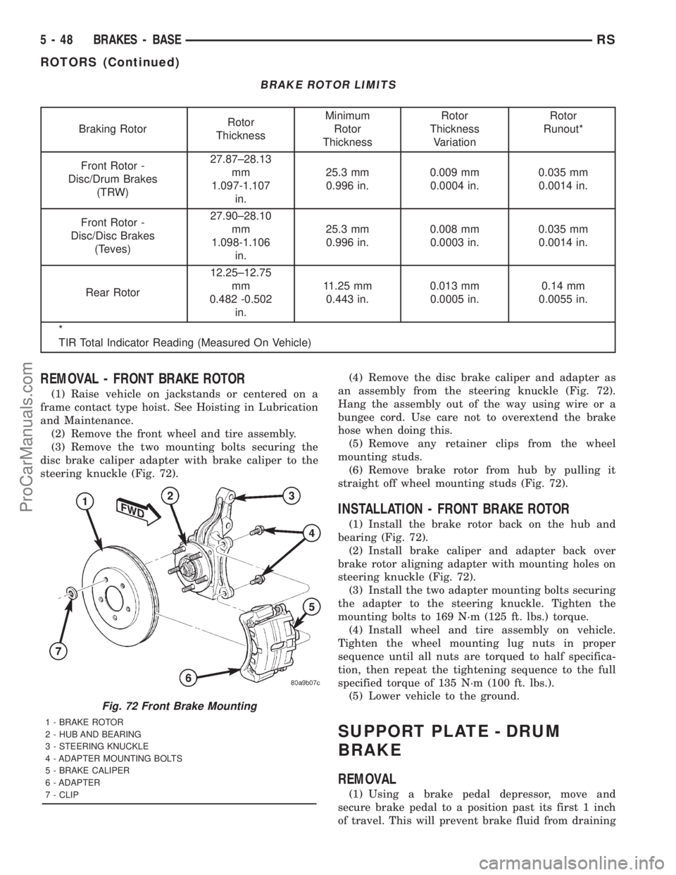
REMOVAL - FRONT BRAKE ROTOR
(1) Raise vehicle on jackstands or centered on a
frame contact type hoist. See Hoisting in Lubrication
and Maintenance.
(2) Remove the front wheel and tire assembly.
(3) Remove the two mounting bolts securing the
disc brake caliper adapter with brake caliper to the
steering knuckle (Fig. 72).(4) Remove the disc brake caliper and adapter as
an assembly from the steering knuckle (Fig. 72).
Hang the assembly out of the way using wire or a
bungee cord. Use care not to overextend the brake
hose when doing this.
(5) Remove any retainer clips from the wheel
mounting studs.
(6) Remove brake rotor from hub by pulling it
straight off wheel mounting studs (Fig. 72).
INSTALLATION - FRONT BRAKE ROTOR
(1) Install the brake rotor back on the hub and
bearing (Fig. 72).
(2) Install brake caliper and adapter back over
brake rotor aligning adapter with mounting holes on
steering knuckle (Fig. 72).
(3) Install the two adapter mounting bolts securing
the adapter to the steering knuckle. Tighten the
mounting bolts to 169 N´m (125 ft. lbs.) torque.
(4) Install wheel and tire assembly on vehicle.
Tighten the wheel mounting lug nuts in proper
sequence until all nuts are torqued to half specifica-
tion, then repeat the tightening sequence to the full
specified torque of 135 N´m (100 ft. lbs.).
(5) Lower vehicle to the ground.
SUPPORT PLATE - DRUM
BRAKE
REMOVAL
(1) Using a brake pedal depressor, move and
secure brake pedal to a position past its first 1 inch
of travel. This will prevent brake fluid from draining
Fig. 72 Front Brake Mounting
1 - BRAKE ROTOR
2 - HUB AND BEARING
3 - STEERING KNUCKLE
4 - ADAPTER MOUNTING BOLTS
5 - BRAKE CALIPER
6 - ADAPTER
7 - CLIP
5 - 48 BRAKES - BASERS
ROTORS (Continued)
ProCarManuals.com
Page 209 of 2321
WHEEL CYLINDERS
REMOVAL
(1) Using a brake pedal depressor, move and
secure brake pedal to a position past its first 1 inch
of travel. This will prevent brake fluid from draining
out of master cylinder when brake tube is remove
from wheel cylinder.
(2) Raise vehicle. (Refer to LUBRICATION &
MAINTENANCE/HOISTING - STANDARD PROCE-
DURE).
(3) Remove wheel and tire assembly.
(4) Disconnect brake tube from rear of wheel cylin-
der. Cap open ends
(5) Remove brake drum.
(6) Remove brake shoes from brake support plate
(Discard if contaminated).(Refer to 5 - BRAKES/HY-
DRAULIC/MECHANICAL/BRAKE PADS/SHOES -
REMOVAL)
(7) Remove the 2 bolts attaching the wheel cylin-
der to the brake support plate.
(8) Remove the wheel cylinder from the brake sup-
port plate.
INSPECTION
With brake drums removed, inspect the wheel cyl-
inder boots for evidence of a brake fluid leak. Visu-
ally check the boots for cuts, tears, or heat cracks. If
any of these conditions exist, the wheel cylinders
should be completely cleaned, inspected and new
parts installed.
If a wheel cylinder is leaking and the brake lining
material is saturated with brake fluid, the brake
shoes must be replaced.
INSTALLATION
(1) Apply sealant such as Mopar Gasket-In-A-Tube
or equivalent around the wheel cylinder opening in
the brake support plate.
(2) Install wheel cylinder onto brake support.
Install and tighten the wheel cylinder to brake sup-
port plate attaching bolts to 8 N´m (75 in. lbs.)
torque.
(3) Install brake tube into wheel cylinder. Tighten
tube nut to a torque of 17 N´m (145 in. lbs.) torque.
(4) Install the rear brake shoes on the brake sup-
port plate. (Refer to 5 - BRAKES/HYDRAULIC/ME-
CHANICAL/BRAKE PADS/SHOES -
INSTALLATION).
(5) Install brake drum.
(6) Install wheel and tire. Install and tighten
wheel lug nuts to 135 N´m (100 ft. lbs.).
(7) Adjust drum brake shoes. (Refer to 5 -
BRAKES/HYDRAULIC/MECHANICAL/BRAKE
PADS/SHOES - ADJUSTMENTS)
(8) Remove brake pedal depressor tool.(9) Bleed the brake system as necessary. (Refer to
5 - BRAKES - BASE - STANDARD PROCEDURE).
(10) Lower vehicle.
PARKING BRAKE
DESCRIPTION
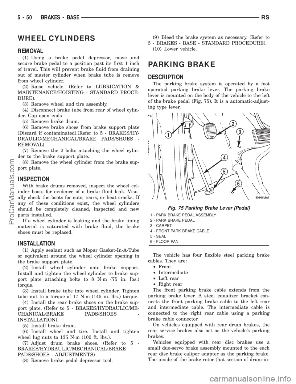
The parking brake system is operated by a foot
operated parking brake lever. The parking brake
lever is mounted on the body of the vehicle to the left
of the brake pedal (Fig. 75). It is a automatic-adjust-
ing type lever.
The vehicle has four flexible steel parking brake
cables. They are:
²Front
²Intermediate
²Left rear
²Right rear
The front parking brake cable extends from the
parking brake lever. A steel equalizer bracket con-
nects the front parking brake cable to the left rear
and intermediate cable. The intermediate cable is
connected to the right rear cable using a parking
brake cable connector.
On vehicles equipped with rear drum brakes, the
rear service brakes also act as the vehicle's parking
brakes.
Vehicles equipped with rear disc brakes use a
small duo-servo brake assembly mounted to the each
rear disc brake caliper adapter as the parking brake.
The inside of the brake rotor (hat section of drum-in-
Fig. 75 Parking Brake Lever (Pedal)
1 - PARK BRAKE PEDAL ASSEMBLY
2 - PARK BRAKE PEDAL
3 - CARPET
4 - FRONT PARK BRAKE CABLE
5 - SEAL
6 - FLOOR PAN
5 - 50 BRAKES - BASERS
ProCarManuals.com
Page 235 of 2321
REMOVAL - ICU
(1) Disconnect the negative (ground) cable from
the battery and isolate cable.
(2) Remove the battery shield.
(3) Remove the battery (Refer to 8 - ELECTRI-
CAL/BATTERY SYSTEM/BATTERY - REMOVAL).
(4) Disconnect the vacuum hose connector at the
tank built into the battery tray.
(5) Remove the screw securing the engine coolant
filler neck to the battery tray.
(6) Remove the battery tray (Refer to 8 - ELEC-
TRICAL/BATTERY SYSTEM/TRAY - REMOVAL).
(7) Using a brake pedal depressor, move and lock
the brake pedal to a position past the first inch of
pedal travel.This will prevent brake fluid from
draining out of the master cylinder once the
brake tubes are removed from the HCU.
CAUTION: Do not apply a 12±volt power source to
any terminals of the 24-way CAB connector when
disconnected.
(8) Disconnect the wiring harness connector from
the speed control servo.
(9) Remove the speed control servo mounting nuts
and move the servo out of the way.
(10) Disconnect the 24±way connector from the
CAB. To disconnect the 24±way connector, grasp the
lock on the 24±way connector and pull it as far up as
possible. This will unlock the 24±way connector from
the socket on the CAB.
CAUTION: Before removing the brake tubes from
the HCU, the HCU must be thoroughly cleaned. This
must be done to prevent dirt particles from falling
into the ports of HCU or entering the brake tubes.
(11) Thoroughly clean all surfaces of the ICU and
brake tube nuts. Use only a solvent such as Mopart
Brake Parts Cleaner or equivalent to clean the ICU.
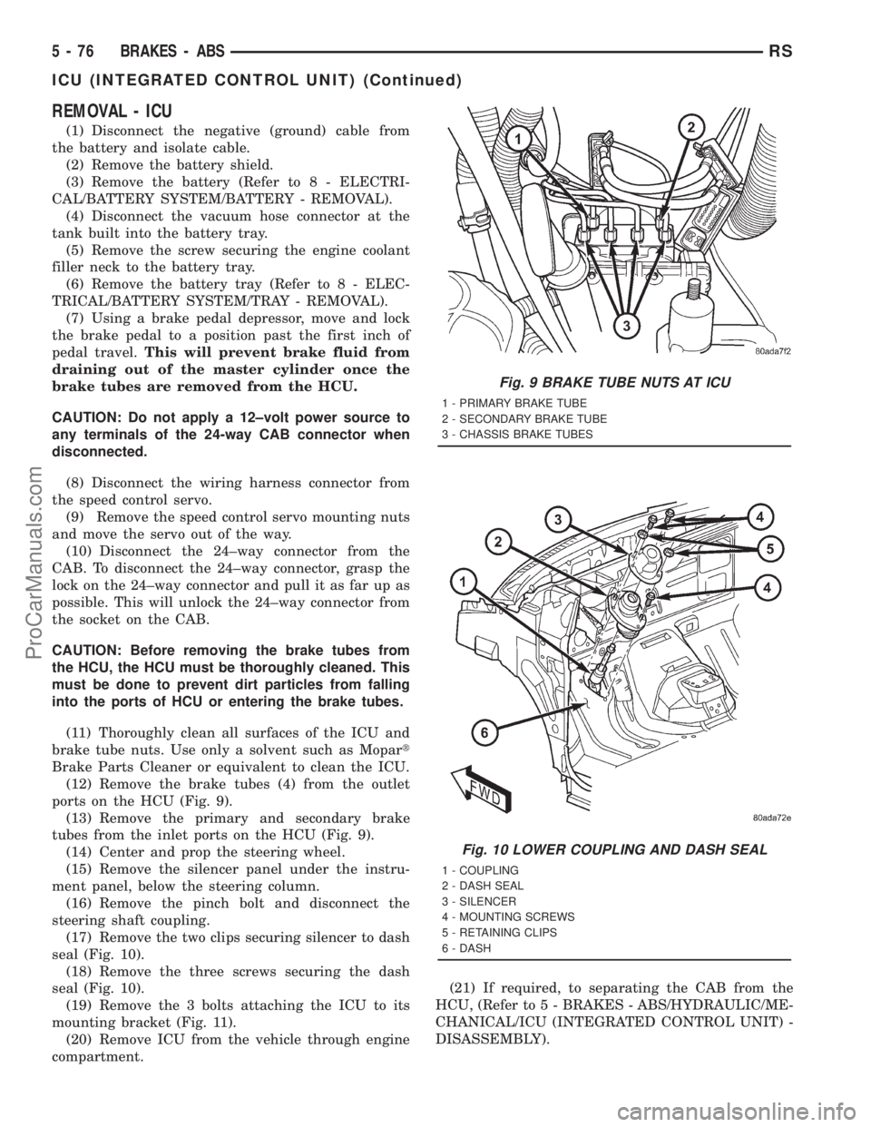
(12) Remove the brake tubes (4) from the outlet
ports on the HCU (Fig. 9).
(13) Remove the primary and secondary brake
tubes from the inlet ports on the HCU (Fig. 9).
(14) Center and prop the steering wheel.
(15) Remove the silencer panel under the instru-
ment panel, below the steering column.
(16) Remove the pinch bolt and disconnect the
steering shaft coupling.
(17) Remove the two clips securing silencer to dash
seal (Fig. 10).
(18) Remove the three screws securing the dash
seal (Fig. 10).
(19) Remove the 3 bolts attaching the ICU to its
mounting bracket (Fig. 11).
(20) Remove ICU from the vehicle through engine
compartment.(21) If required, to separating the CAB from the
HCU, (Refer to 5 - BRAKES - ABS/HYDRAULIC/ME-
CHANICAL/ICU (INTEGRATED CONTROL UNIT) -
DISASSEMBLY).
Fig. 9 BRAKE TUBE NUTS AT ICU
1 - PRIMARY BRAKE TUBE
2 - SECONDARY BRAKE TUBE
3 - CHASSIS BRAKE TUBES
Fig. 10 LOWER COUPLING AND DASH SEAL
1 - COUPLING
2 - DASH SEAL
3 - SILENCER
4 - MOUNTING SCREWS
5 - RETAINING CLIPS
6 - DASH
5 - 76 BRAKES - ABSRS
ICU (INTEGRATED CONTROL UNIT) (Continued)
ProCarManuals.com