2001 DODGE TOWN AND COUNTRY drain bolt
[x] Cancel search: drain boltPage 1318 of 2321
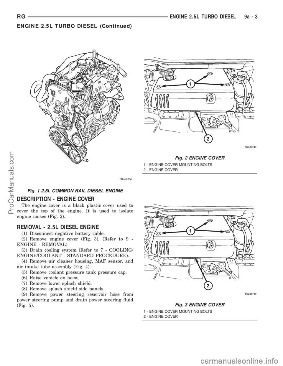
DESCRIPTION - ENGINE COVER
The engine cover is a black plastic cover used to
cover the top of the engine. It is used to isolate
engine noises (Fig. 2).
REMOVAL - 2.5L DIESEL ENGINE
(1) Disconnect negative battery cable.
(2) Remove engine cover (Fig. 3). (Refer to 9 -
ENGINE - REMOVAL)
(3) Drain cooling system (Refer to 7 - COOLING/
ENGINE/COOLANT - STANDARD PROCEDURE).
(4) Remove air cleaner housing, MAF sensor, and
air intake tube assembly (Fig. 4).
(5) Remove coolant pressure tank pressure cap.
(6) Raise vehicle on hoist.
(7) Remove lower splash shield.
(8) Remove splash shield side panels.
(9) Remove power steering reservoir hose from
power steering pump and drain power steering fluid
(Fig. 5).
Fig. 1 2.5L COMMON RAIL DIESEL ENGINE
Fig. 2 ENGINE COVER
1 - ENGINE COVER MOUNTING BOLTS
2 - ENGINE COVER
Fig. 3 ENGINE COVER
1 - ENGINE COVER MOUNTING BOLTS
2 - ENGINE COVER
RGENGINE 2.5L TURBO DIESEL9a-3
ENGINE 2.5L TURBO DIESEL (Continued)
ProCarManuals.com
Page 1335 of 2321
Measure Dimension
(mm)0.40-0.60
Cylinder Head Gasket
Thickness (mm)1.32
Piston Clearance (mm) 0.73-0.92
Measure Dimension
(mm)0.61-0.70
Cylinder Head Gasket
Thickness (mm)1.42
Piston Clearance (mm) 0.72-0.82
Measure Dimension
(mm)0.69-0.81
Cylinder Head Gasket
Thickness (mm)1.52
Piston Clearance (mm) 0.80-0.89
(5) Repeat the procedure with the rest of the cyl-
inders.
(6) Establish the thickness of the steel gasket for
all four cylinders on the basis of the greatest piston
protrusion.
REMOVAL
(1) Disconnect negative battery cable.
(2) Remove front wiper unit (Refer to 8 - ELEC-
TRICAL/WIPERS/WASHERS/WIPER MODULE -
REMOVAL).
(3) Remove engine cover (Refer to 9 - ENGINE -
REMOVAL).
(4) Drain cooling system (Refer to 7 - COOLING/
ENGINE/COOLANT - STANDARD PROCEDURE).
(5) Remove power steering belt (Refer to 7 -
COOLING/ACCESSORY DRIVE/DRIVE BELTS -
REMOVAL).
(6) Remove accessory drive belt (Refer to 7 -
COOLING/ACCESSORY DRIVE/DRIVE BELTS -
REMOVAL).
(7) Remove generator (Refer to 8 - ELECTRICAL/
CHARGING/GENERATOR - REMOVAL).
(8) Support engine and remove right engine mount
(Refer to 9 - ENGINE/ENGINE MOUNTING/RIGHT
MOUNT - REMOVAL).
CAUTION: Before removing the cylinder head cover/
intake manifold or timing belt the engine must put
at 90É after TDC. Failure to do so could result in
valve and/or piston damage during reassembly.
(Refer to 9 - ENGINE/VALVE TIMING - STANDARD
PROCEDURE)(9) Remove timing belt outer cover (Refer to 9 -
ENGINE/VALVE TIMING/TIMING BELT / CHAIN
COVER(S) - REMOVAL).
(10) Remove timing belt (Refer to 9 - ENGINE/
VALVE TIMING/TIMING BELT/CHAIN AND
SPROCKETS - REMOVAL).
(11) Remove timing belt inner cover (Refer to 9 -
ENGINE/VALVE TIMING/TIMING BELT / CHAIN
COVER(S) - REMOVAL).
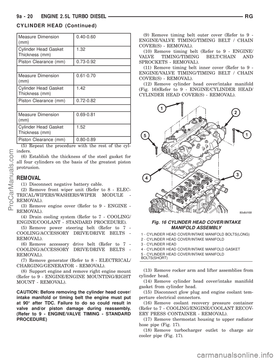
(12) Remove cylinder head cover/intake manifold
(Fig. 16)(Refer to 9 - ENGINE/CYLINDER HEAD/
CYLINDER HEAD COVER(S) - REMOVAL).
(13) Remove rocker arm and lifter assemblies from
cylinder head.
(14) Remove cylinder head cover/intake manifold
gasket from cylinder head.
(15) Disconnect glow plug and engine coolant tem-
perture electrical connectors.
(16) Remove coolant recovery pressure container
(Refer to 7 - COOLING/ENGINE/COOLANT RECOV-
ERY PRESS CONTAINER - REMOVAL).
(17) Remove thermostat housing to upper radiator
hose pipe (Fig. 17).
(18) Remove turbocharger outlet to charge air
cooler pipe (Fig. 17).
Fig. 16 CYLINDER HEAD COVER/INTAKE
MANIFOLD ASSEMBLY
1 - CYLINDER HEAD COVER/INTAKE MANIFOLD BOLTS(LONG)
2 - CYLINDER HEAD COVER/INTAKE MANIFOLD
3 - CYLINDER HEAD
4 - CYLINDER HEAD COVER/INTAKE MANIFOLD GASKET
5 - CYLINDER HEAD COVER/INTAKE MANIFOLD
BOLTS(SHORT)
9a - 20 ENGINE 2.5L TURBO DIESELRG
CYLINDER HEAD (Continued)
ProCarManuals.com
Page 1347 of 2321
STANDARD PROCEDURE - CHECKING
CRANKSHAFT END PLAY
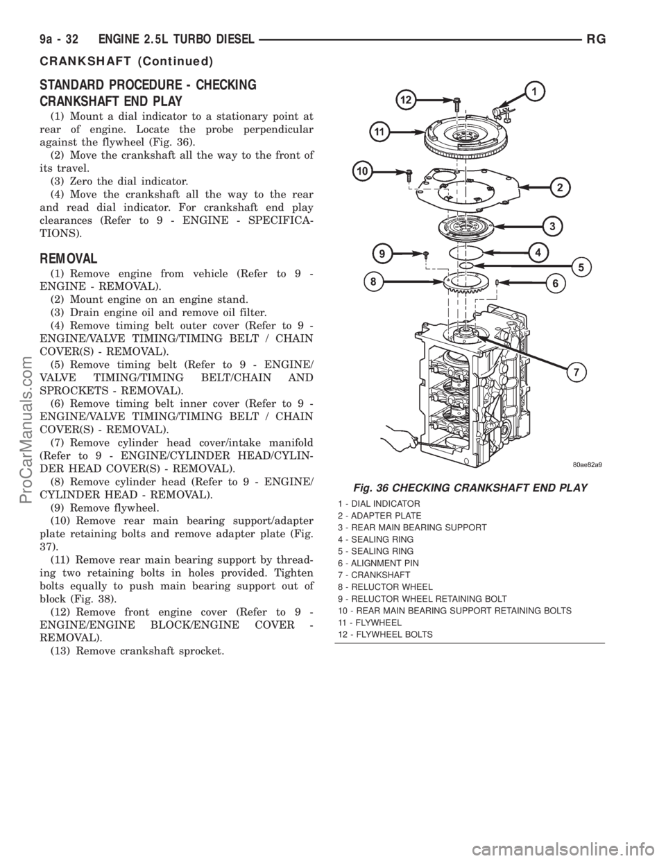
(1) Mount a dial indicator to a stationary point at
rear of engine. Locate the probe perpendicular
against the flywheel (Fig. 36).
(2) Move the crankshaft all the way to the front of
its travel.
(3) Zero the dial indicator.
(4) Move the crankshaft all the way to the rear
and read dial indicator. For crankshaft end play
clearances (Refer to 9 - ENGINE - SPECIFICA-
TIONS).
REMOVAL
(1) Remove engine from vehicle (Refer to 9 -
ENGINE - REMOVAL).
(2) Mount engine on an engine stand.
(3) Drain engine oil and remove oil filter.
(4) Remove timing belt outer cover (Refer to 9 -
ENGINE/VALVE TIMING/TIMING BELT / CHAIN
COVER(S) - REMOVAL).
(5) Remove timing belt (Refer to 9 - ENGINE/
VALVE TIMING/TIMING BELT/CHAIN AND
SPROCKETS - REMOVAL).
(6) Remove timing belt inner cover (Refer to 9 -
ENGINE/VALVE TIMING/TIMING BELT / CHAIN
COVER(S) - REMOVAL).
(7) Remove cylinder head cover/intake manifold
(Refer to 9 - ENGINE/CYLINDER HEAD/CYLIN-
DER HEAD COVER(S) - REMOVAL).
(8) Remove cylinder head (Refer to 9 - ENGINE/
CYLINDER HEAD - REMOVAL).
(9) Remove flywheel.
(10) Remove rear main bearing support/adapter
plate retaining bolts and remove adapter plate (Fig.
37).
(11) Remove rear main bearing support by thread-
ing two retaining bolts in holes provided. Tighten
bolts equally to push main bearing support out of
block (Fig. 38).
(12) Remove front engine cover (Refer to 9 -
ENGINE/ENGINE BLOCK/ENGINE COVER -
REMOVAL).
(13) Remove crankshaft sprocket.
Fig. 36 CHECKING CRANKSHAFT END PLAY
1 - DIAL INDICATOR
2 - ADAPTER PLATE
3 - REAR MAIN BEARING SUPPORT
4 - SEALING RING
5 - SEALING RING
6 - ALIGNMENT PIN
7 - CRANKSHAFT
8 - RELUCTOR WHEEL
9 - RELUCTOR WHEEL RETAINING BOLT
10 - REAR MAIN BEARING SUPPORT RETAINING BOLTS
11 - FLYWHEEL
12 - FLYWHEEL BOLTS
9a - 32 ENGINE 2.5L TURBO DIESELRG
CRANKSHAFT (Continued)
ProCarManuals.com
Page 1361 of 2321
INSTALLATION
CRANKSHAFT MAIN BEARINGS
(1) Install bearing halves in crankshaft supports.
(2) Lubricate crankshaft and main bearings with
clean engine oil.
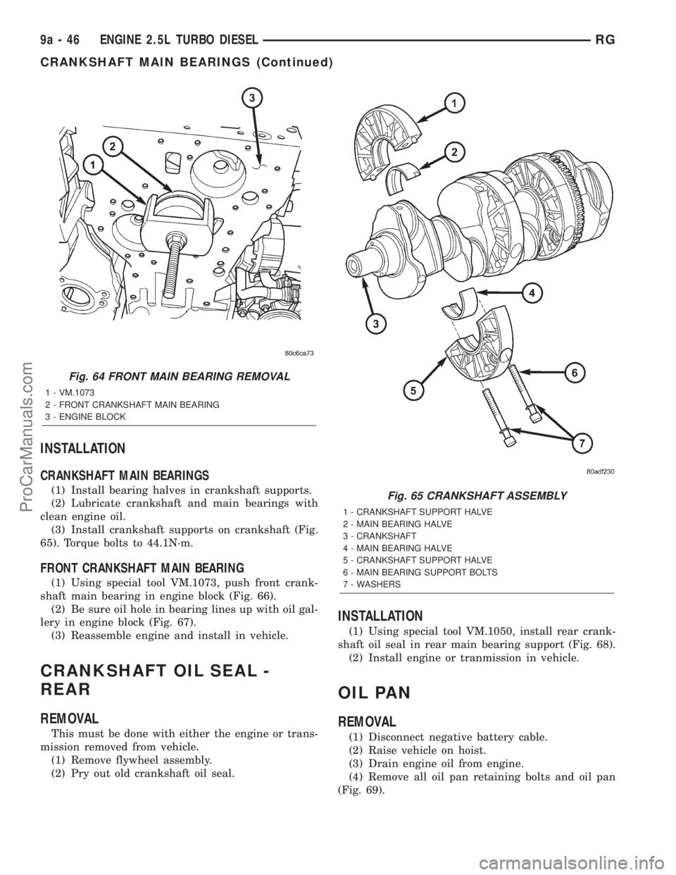
(3) Install crankshaft supports on crankshaft (Fig.
65). Torque bolts to 44.1N´m.
FRONT CRANKSHAFT MAIN BEARING
(1) Using special tool VM.1073, push front crank-
shaft main bearing in engine block (Fig. 66).
(2) Be sure oil hole in bearing lines up with oil gal-
lery in engine block (Fig. 67).
(3) Reassemble engine and install in vehicle.
CRANKSHAFT OIL SEAL -
REAR
REMOVAL
This must be done with either the engine or trans-
mission removed from vehicle.
(1) Remove flywheel assembly.
(2) Pry out old crankshaft oil seal.
INSTALLATION
(1) Using special tool VM.1050, install rear crank-
shaft oil seal in rear main bearing support (Fig. 68).
(2) Install engine or tranmission in vehicle.
OIL PAN
REMOVAL
(1) Disconnect negative battery cable.
(2) Raise vehicle on hoist.
(3) Drain engine oil from engine.
(4) Remove all oil pan retaining bolts and oil pan
(Fig. 69).
Fig. 64 FRONT MAIN BEARING REMOVAL
1 - VM.1073
2 - FRONT CRANKSHAFT MAIN BEARING
3 - ENGINE BLOCK
Fig. 65 CRANKSHAFT ASSEMBLY
1 - CRANKSHAFT SUPPORT HALVE
2 - MAIN BEARING HALVE
3 - CRANKSHAFT
4 - MAIN BEARING HALVE
5 - CRANKSHAFT SUPPORT HALVE
6 - MAIN BEARING SUPPORT BOLTS
7 - WASHERS
9a - 46 ENGINE 2.5L TURBO DIESELRG
CRANKSHAFT MAIN BEARINGS (Continued)
ProCarManuals.com
Page 1366 of 2321
REMOVAL
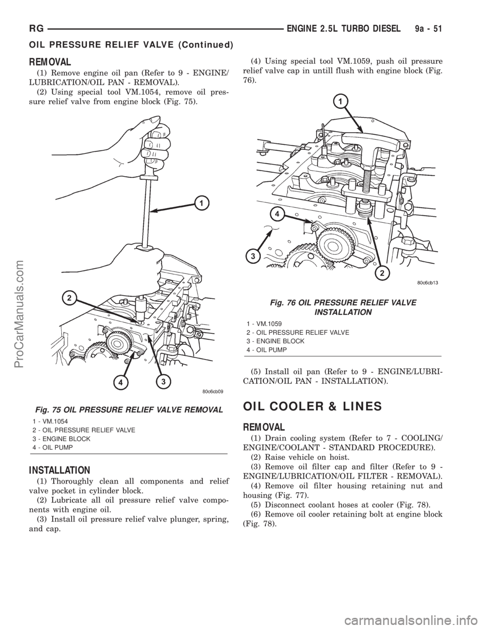
(1) Remove engine oil pan (Refer to 9 - ENGINE/
LUBRICATION/OIL PAN - REMOVAL).
(2) Using special tool VM.1054, remove oil pres-
sure relief valve from engine block (Fig. 75).
INSTALLATION
(1) Thoroughly clean all components and relief
valve pocket in cylinder block.
(2) Lubricate all oil pressure relief valve compo-
nents with engine oil.
(3) Install oil pressure relief valve plunger, spring,
and cap.(4) Using special tool VM.1059, push oil pressure
relief valve cap in untill flush with engine block (Fig.
76).
(5) Install oil pan (Refer to 9 - ENGINE/LUBRI-
CATION/OIL PAN - INSTALLATION).
OIL COOLER & LINES
REMOVAL
(1) Drain cooling system (Refer to 7 - COOLING/
ENGINE/COOLANT - STANDARD PROCEDURE).
(2) Raise vehicle on hoist.
(3) Remove oil filter cap and filter (Refer to 9 -
ENGINE/LUBRICATION/OIL FILTER - REMOVAL).
(4) Remove oil filter housing retaining nut and
housing (Fig. 77).
(5) Disconnect coolant hoses at cooler (Fig. 78).
(6) Remove oil cooler retaining bolt at engine block
(Fig. 78).
Fig. 75 OIL PRESSURE RELIEF VALVE REMOVAL
1 - VM.1054
2 - OIL PRESSURE RELIEF VALVE
3 - ENGINE BLOCK
4 - OIL PUMP
Fig. 76 OIL PRESSURE RELIEF VALVE
INSTALLATION
1 - VM.1059
2 - OIL PRESSURE RELIEF VALVE
3 - ENGINE BLOCK
4 - OIL PUMP
RGENGINE 2.5L TURBO DIESEL9a-51
OIL PRESSURE RELIEF VALVE (Continued)
ProCarManuals.com
Page 1367 of 2321
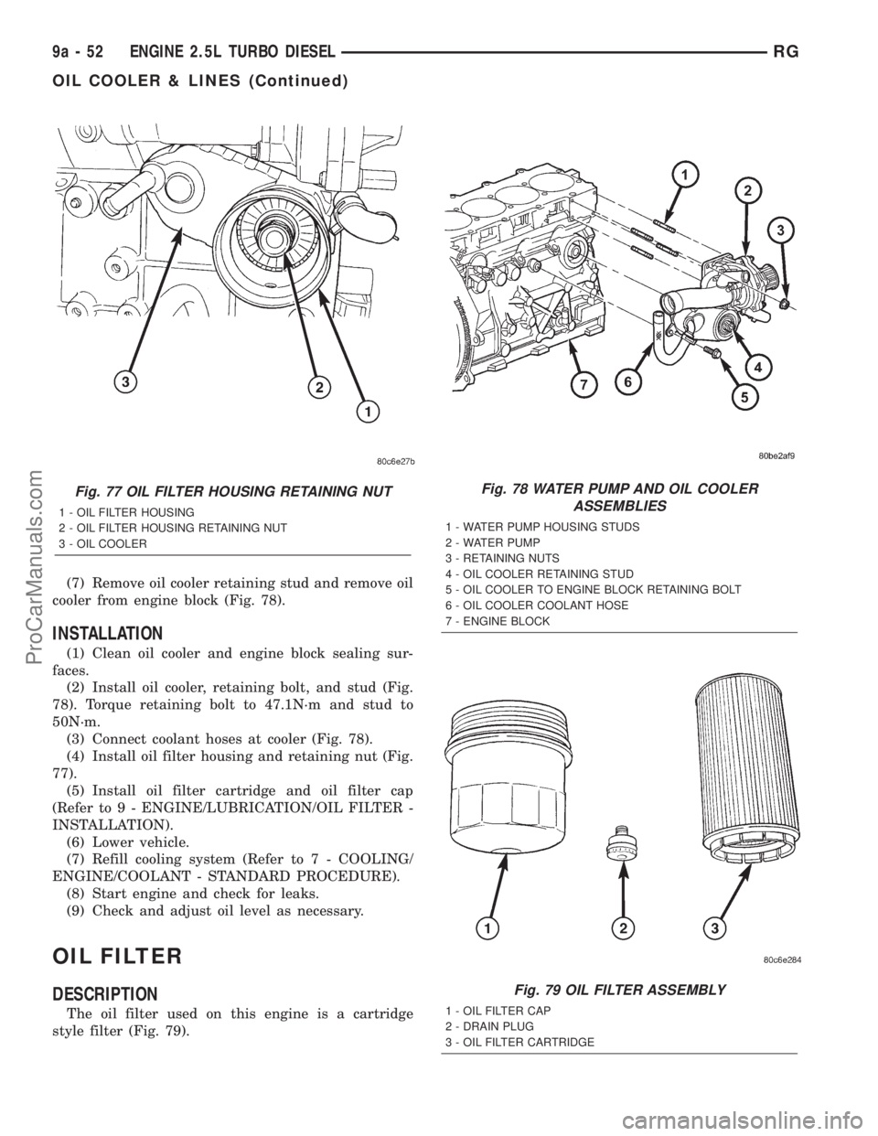
(7) Remove oil cooler retaining stud and remove oil
cooler from engine block (Fig. 78).
INSTALLATION
(1) Clean oil cooler and engine block sealing sur-
faces.
(2) Install oil cooler, retaining bolt, and stud (Fig.
78). Torque retaining bolt to 47.1N´m and stud to
50N´m.
(3) Connect coolant hoses at cooler (Fig. 78).
(4) Install oil filter housing and retaining nut (Fig.
77).
(5) Install oil filter cartridge and oil filter cap
(Refer to 9 - ENGINE/LUBRICATION/OIL FILTER -
INSTALLATION).
(6) Lower vehicle.
(7) Refill cooling system (Refer to 7 - COOLING/
ENGINE/COOLANT - STANDARD PROCEDURE).
(8) Start engine and check for leaks.
(9) Check and adjust oil level as necessary.
OIL FILTER
DESCRIPTION
The oil filter used on this engine is a cartridge
style filter (Fig. 79).
Fig. 77 OIL FILTER HOUSING RETAINING NUT
1 - OIL FILTER HOUSING
2 - OIL FILTER HOUSING RETAINING NUT
3 - OIL COOLER
Fig. 78 WATER PUMP AND OIL COOLER
ASSEMBLIES
1 - WATER PUMP HOUSING STUDS
2 - WATER PUMP
3 - RETAINING NUTS
4 - OIL COOLER RETAINING STUD
5 - OIL COOLER TO ENGINE BLOCK RETAINING BOLT
6 - OIL COOLER COOLANT HOSE
7 - ENGINE BLOCK
Fig. 79 OIL FILTER ASSEMBLY
1 - OIL FILTER CAP
2 - DRAIN PLUG
3 - OIL FILTER CARTRIDGE
9a - 52 ENGINE 2.5L TURBO DIESELRG
OIL COOLER & LINES (Continued)
ProCarManuals.com
Page 1368 of 2321
REMOVAL
(1) Raise vehicle on hoist.
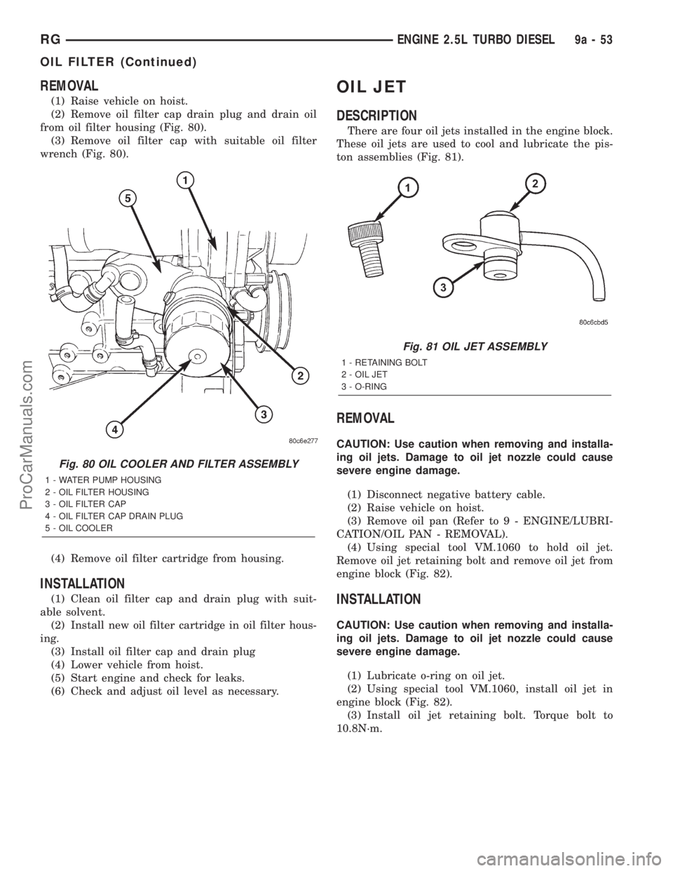
(2) Remove oil filter cap drain plug and drain oil
from oil filter housing (Fig. 80).
(3) Remove oil filter cap with suitable oil filter
wrench (Fig. 80).
(4) Remove oil filter cartridge from housing.
INSTALLATION
(1) Clean oil filter cap and drain plug with suit-
able solvent.
(2) Install new oil filter cartridge in oil filter hous-
ing.
(3) Install oil filter cap and drain plug
(4) Lower vehicle from hoist.
(5) Start engine and check for leaks.
(6) Check and adjust oil level as necessary.
OIL JET
DESCRIPTION
There are four oil jets installed in the engine block.
These oil jets are used to cool and lubricate the pis-
ton assemblies (Fig. 81).
REMOVAL
CAUTION: Use caution when removing and installa-
ing oil jets. Damage to oil jet nozzle could cause
severe engine damage.
(1) Disconnect negative battery cable.
(2) Raise vehicle on hoist.
(3) Remove oil pan (Refer to 9 - ENGINE/LUBRI-
CATION/OIL PAN - REMOVAL).
(4) Using special tool VM.1060 to hold oil jet.
Remove oil jet retaining bolt and remove oil jet from
engine block (Fig. 82).
INSTALLATION
CAUTION: Use caution when removing and installa-
ing oil jets. Damage to oil jet nozzle could cause
severe engine damage.
(1) Lubricate o-ring on oil jet.
(2) Using special tool VM.1060, install oil jet in
engine block (Fig. 82).
(3) Install oil jet retaining bolt. Torque bolt to
10.8N´m.
Fig. 80 OIL COOLER AND FILTER ASSEMBLY
1 - WATER PUMP HOUSING
2 - OIL FILTER HOUSING
3 - OIL FILTER CAP
4 - OIL FILTER CAP DRAIN PLUG
5 - OIL COOLER
Fig. 81 OIL JET ASSEMBLY
1 - RETAINING BOLT
2 - OIL JET
3 - O-RING
RGENGINE 2.5L TURBO DIESEL9a-53
OIL FILTER (Continued)
ProCarManuals.com
Page 1392 of 2321
(8) With exhaust manifold and turbocharger
assembly on work bench, remove turbocharger to
exhaust manifold retaining bolts. Separate exhaust
manifold and turbocharger.
CLEANING
All old gaskets should be inspected for any tears or
signs of prior leakage. If any gaskets show such indi-
cations, they should be replaced with new gaskets.
All gasket mating surfaces must be cleaned of old
gasket material to produce a smooth and dirt free
sealing surface for the new gasket.
INSTALLATION
(1) Connect exhaust manifold and turbocharger.
Torque nuts to 32.4N´m.
(2) Position new exhaust manifol gasket on
exhaust manifol studs (Fig. 6).
(3) Install exhaust manifold and turbocharger on
engine (Fig. 6). Torque nuts to 32.4N´m.
(4) Connect turbocharger oil supply and return
lines at turbocharger (Fig. 6). Torque oil supply line
to 24.5N´m.
(5) Install exhaust manifold shield (Fig. 6). Torque
bolts to 27.5N´m.
(6) Install engine lift hook (Fig. 6). Torque bolts to
32.4N´m.
(7) Install thermostat to upper radiator hose tube
and turbocharger outlet tube (Fig. 5).
(8) Install engine in vehicle (Refer to 9 - ENGINE
- INSTALLATION).
HEAT SHIELDS
REMOVAL
(1) Remove front wiper unit (Refer to 8 - ELEC-
TRICAL/WIPERS/WASHERS/WIPER MODULE -
REMOVAL).
(2) Remove engine cover (Refer to 9 - ENGINE -
REMOVAL).
(3) Partially drain cooling system (Refer to 7 -
COOLING/ENGINE/COOLANT - STANDARD PRO-
CEDURE).
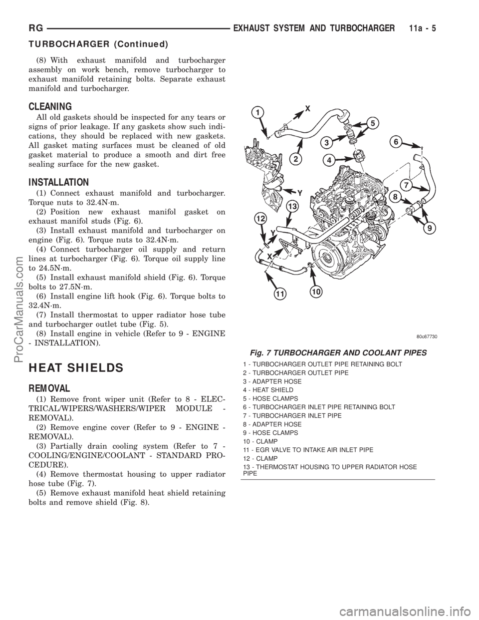
(4) Remove thermostat housing to upper radiator
hose tube (Fig. 7).
(5) Remove exhaust manifold heat shield retaining
bolts and remove shield (Fig. 8).
Fig. 7 TURBOCHARGER AND COOLANT PIPES
1 - TURBOCHARGER OUTLET PIPE RETAINING BOLT
2 - TURBOCHARGER OUTLET PIPE
3 - ADAPTER HOSE
4 - HEAT SHIELD
5 - HOSE CLAMPS
6 - TURBOCHARGER INLET PIPE RETAINING BOLT
7 - TURBOCHARGER INLET PIPE
8 - ADAPTER HOSE
9 - HOSE CLAMPS
10 - CLAMP
11 - EGR VALVE TO INTAKE AIR INLET PIPE
12 - CLAMP
13 - THERMOSTAT HOUSING TO UPPER RADIATOR HOSE
PIPE
RGEXHAUST SYSTEM AND TURBOCHARGER11a-5
TURBOCHARGER (Continued)
ProCarManuals.com