2001 DODGE TOWN AND COUNTRY drain bolt
[x] Cancel search: drain boltPage 286 of 2321
DIAGNOSIS AND TESTING - COOLANT
RECOVERY SYSTEM
The cooling system is closed and designed to main-
tain coolant level to the top of the radiator.
(1) With the engineoffand cooling systemnot
under pressure, drain several ounces of coolant from
the radiator draincock while observing the coolant
recovery container. Coolant level in the container
should drop.
(2) Remove the radiator pressure cap. The coolant
level should be full to the top radiator neck. If not,
and the coolant level in the container is at or above
the MIN mark, there is an air leak in the coolant
recovery system.
(3) Check hose and hose connections to the con-
tainer, radiator filler neck or the pressure cap seal to
the radiator filler neck for leaks.
REMOVAL
(1) Raise the vehicle on hoist.
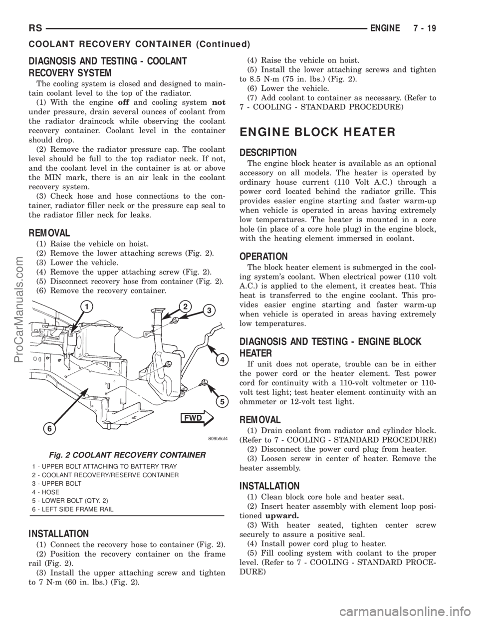
(2) Remove the lower attaching screws (Fig. 2).
(3) Lower the vehicle.
(4) Remove the upper attaching screw (Fig. 2).
(5)
Disconnect recovery hose from container (Fig. 2).
(6) Remove the recovery container.
INSTALLATION
(1) Connect the recovery hose to container (Fig. 2).
(2) Position the recovery container on the frame
rail (Fig. 2).
(3) Install the upper attaching screw and tighten
to 7 N´m (60 in. lbs.) (Fig. 2).(4) Raise the vehicle on hoist.
(5) Install the lower attaching screws and tighten
to 8.5 N´m (75 in. lbs.) (Fig. 2).
(6) Lower the vehicle.
(7) Add coolant to container as necessary. (Refer to
7 - COOLING - STANDARD PROCEDURE)
ENGINE BLOCK HEATER
DESCRIPTION
The engine block heater is available as an optional
accessory on all models. The heater is operated by
ordinary house current (110 Volt A.C.) through a
power cord located behind the radiator grille. This
provides easier engine starting and faster warm-up
when vehicle is operated in areas having extremely
low temperatures. The heater is mounted in a core
hole (in place of a core hole plug) in the engine block,
with the heating element immersed in coolant.
OPERATION
The block heater element is submerged in the cool-
ing system's coolant. When electrical power (110 volt
A.C.) is applied to the element, it creates heat. This
heat is transferred to the engine coolant. This pro-
vides easier engine starting and faster warm-up
when vehicle is operated in areas having extremely
low temperatures.
DIAGNOSIS AND TESTING - ENGINE BLOCK
HEATER
If unit does not operate, trouble can be in either
the power cord or the heater element. Test power
cord for continuity with a 110-volt voltmeter or 110-
volt test light; test heater element continuity with an
ohmmeter or 12-volt test light.
REMOVAL
(1) Drain coolant from radiator and cylinder block.
(Refer to 7 - COOLING - STANDARD PROCEDURE)
(2) Disconnect the power cord plug from heater.
(3) Loosen screw in center of heater. Remove the
heater assembly.
INSTALLATION
(1) Clean block core hole and heater seat.
(2) Insert heater assembly with element loop posi-
tionedupward.
(3) With heater seated, tighten center screw
securely to assure a positive seal.
(4) Install power cord plug to heater.
(5) Fill cooling system with coolant to the proper
level. (Refer to 7 - COOLING - STANDARD PROCE-
DURE)
Fig. 2 COOLANT RECOVERY CONTAINER
1 - UPPER BOLT ATTACHING TO BATTERY TRAY
2 - COOLANT RECOVERY/RESERVE CONTAINER
3 - UPPER BOLT
4 - HOSE
5 - LOWER BOLT (QTY. 2)
6 - LEFT SIDE FRAME RAIL
RSENGINE7-19
COOLANT RECOVERY CONTAINER (Continued)
ProCarManuals.com
Page 287 of 2321
ENGINE COOLANT TEMP
SENSOR - 2.4L
DESCRIPTION
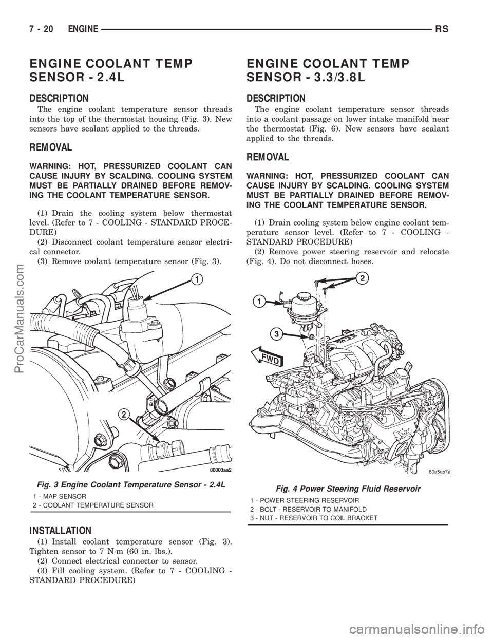
The engine coolant temperature sensor threads
into the top of the thermostat housing (Fig. 3). New
sensors have sealant applied to the threads.
REMOVAL
WARNING: HOT, PRESSURIZED COOLANT CAN
CAUSE INJURY BY SCALDING. COOLING SYSTEM
MUST BE PARTIALLY DRAINED BEFORE REMOV-
ING THE COOLANT TEMPERATURE SENSOR.
(1) Drain the cooling system below thermostat
level. (Refer to 7 - COOLING - STANDARD PROCE-
DURE)
(2) Disconnect coolant temperature sensor electri-
cal connector.
(3) Remove coolant temperature sensor (Fig. 3).
INSTALLATION
(1) Install coolant temperature sensor (Fig. 3).
Tighten sensor to 7 N´m (60 in. lbs.).
(2) Connect electrical connector to sensor.
(3) Fill cooling system. (Refer to 7 - COOLING -
STANDARD PROCEDURE)
ENGINE COOLANT TEMP
SENSOR - 3.3/3.8L
DESCRIPTION
The engine coolant temperature sensor threads
into a coolant passage on lower intake manifold near
the thermostat (Fig. 6). New sensors have sealant
applied to the threads.
REMOVAL
WARNING: HOT, PRESSURIZED COOLANT CAN
CAUSE INJURY BY SCALDING. COOLING SYSTEM
MUST BE PARTIALLY DRAINED BEFORE REMOV-
ING THE COOLANT TEMPERATURE SENSOR.
(1) Drain cooling system below engine coolant tem-
perature sensor level. (Refer to 7 - COOLING -
STANDARD PROCEDURE)
(2) Remove power steering reservoir and relocate
(Fig. 4). Do not disconnect hoses.
Fig. 3 Engine Coolant Temperature Sensor - 2.4L
1 - MAP SENSOR
2 - COOLANT TEMPERATURE SENSORFig. 4 Power Steering Fluid Reservoir
1 - POWER STEERING RESERVOIR
2 - BOLT - RESERVOIR TO MANIFOLD
3 - NUT - RESERVOIR TO COIL BRACKET
7 - 20 ENGINERS
ProCarManuals.com
Page 289 of 2321
DIAGNOSIS AND TESTING - ENGINE COOLANT
THERMOSTAT
The thermostat is operated by a wax filled cham-
ber (pellet) which is sealed. When heated coolant
reaches a predetermined temperature the wax pellet
expands enough to overcome the closing spring and
water pump pressure, which forces the valve to open.
Coolant leakage into the pellet will cause a thermo-
stat to fail open. Do not attempt to free up a thermo-
stat with a screwdriver.
Thermostat diagnostics is included in powertrain
control module's (PCM) programing for on-board
diagnosis. The malfunction indicator light (MIL) will
illuminate and a diagnostic trouble code (DTC) will
be set when an ªopen too soonº condition occurs. Do
not change a thermostat for lack of heater perfor-
mance or temperature gauge position, unless a DTC
is present. For other probable causes, (Refer to 7 -
COOLING/ENGINE - DIAGNOSIS AND TESTING) .
Thermostat failing shut is the normal long term
mode of failure, and normally, only on high mileage
vehicles. The temperature gauge will indicate this
(Refer to 7 - COOLING/ENGINE - DIAGNOSIS AND
TESTING) .
ENGINE COOLANT
THERMOSTAT - 2.4L
REMOVAL
(1) Drain cooling system below the thermostat
level. (Refer to 7 - COOLING - STANDARD PROCE-
DURE)
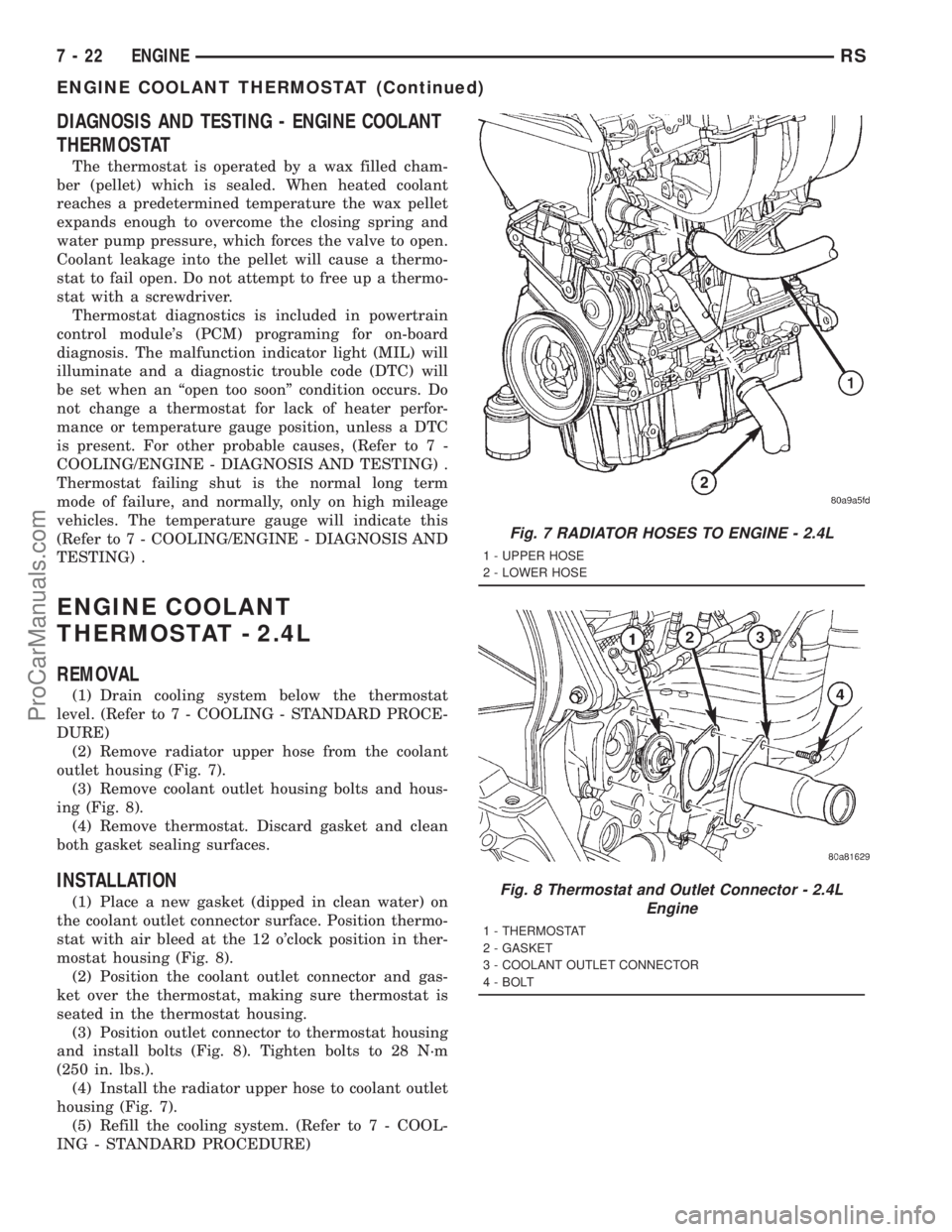
(2) Remove radiator upper hose from the coolant
outlet housing (Fig. 7).
(3) Remove coolant outlet housing bolts and hous-
ing (Fig. 8).
(4) Remove thermostat. Discard gasket and clean
both gasket sealing surfaces.
INSTALLATION
(1) Place a new gasket (dipped in clean water) on
the coolant outlet connector surface. Position thermo-
stat with air bleed at the 12 o'clock position in ther-
mostat housing (Fig. 8).
(2) Position the coolant outlet connector and gas-
ket over the thermostat, making sure thermostat is
seated in the thermostat housing.
(3) Position outlet connector to thermostat housing
and install bolts (Fig. 8). Tighten bolts to 28 N´m
(250 in. lbs.).
(4) Install the radiator upper hose to coolant outlet
housing (Fig. 7).
(5) Refill the cooling system. (Refer to 7 - COOL-
ING - STANDARD PROCEDURE)
Fig. 7 RADIATOR HOSES TO ENGINE - 2.4L
1 - UPPER HOSE
2 - LOWER HOSE
Fig. 8 Thermostat and Outlet Connector - 2.4L
Engine
1 - THERMOSTAT
2 - GASKET
3 - COOLANT OUTLET CONNECTOR
4 - BOLT
7 - 22 ENGINERS
ENGINE COOLANT THERMOSTAT (Continued)
ProCarManuals.com
Page 290 of 2321
ENGINE COOLANT
THERMOSTAT - 3.3/3.8L
REMOVAL
(1) Drain cooling system down below the thermo-
stat level. (Refer to 7 - COOLING - STANDARD
PROCEDURE)
(2) Remove radiator upper hose from coolant outlet
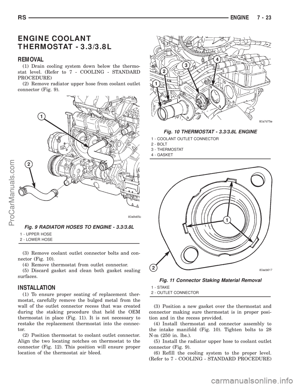
connector (Fig. 9).
(3) Remove coolant outlet connector bolts and con-
nector (Fig. 10).
(4) Remove thermostat from outlet connector.
(5) Discard gasket and clean both gasket sealing
surfaces.
INSTALLATION
(1) To ensure proper seating of replacement ther-
mostat, carefully remove the bulged metal from the
wall of the outlet connector recess that was created
during the staking procedure that held the OEM
thermostat in place (Fig. 11). It is not necessary to
restake the replacement thermostat into the connec-
tor.
(2) Position thermostat to coolant outlet connector.
Align the two locating notches on thermostat to the
connector (Fig. 12). This position will ensure proper
location of the thermostat air bleed.(3) Position a new gasket over the thermostat and
connector making sure thermostat is in proper posi-
tion and in the recess provided.
(4) Install thermostat and connector assembly to
the intake manifold (Fig. 10). Tighten bolts to 28
N´m (250 in. lbs.).
(5) Install the radiator upper hose to coolant outlet
connector (Fig. 9).
(6) Refill the cooling system to the proper level.
(Refer to 7 - COOLING - STANDARD PROCEDURE)
Fig. 9 RADIATOR HOSES TO ENGINE - 3.3/3.8L
1 - UPPER HOSE
2 - LOWER HOSE
Fig. 10 THERMOSTAT - 3.3/3.8L ENGINE
1 - COOLANT OUTLET CONNECTOR
2 - BOLT
3 - THERMOSTAT
4 - GASKET
Fig. 11 Connector Staking Material Removal
1-STAKE
2 - OUTLET CONNECTOR
RSENGINE7-23
ProCarManuals.com
Page 297 of 2321
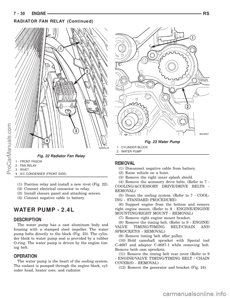
(1) Position relay and install a new rivet (Fig. 22).
(2) Connect electrical connector to relay.
(3) Install closure panel and attaching screws.
(4) Connect negative cable to battery.
WATER PUMP - 2.4L
DESCRIPTION
The water pump has a cast aluminum body and
housing with a stamped steel impeller. The water
pump bolts directly to the block (Fig. 23). The cylin-
der block to water pump seal is provided by a rubber
O-ring. The water pump is driven by the engine tim-
ing belt.
OPERATION
The water pump is the heart of the cooling system.
The coolant is pumped through the engine block, cyl-
inder head, heater core, and radiator.
REMOVAL
(1) Disconnect negative cable from battery.
(2) Raise vehicle on a hoist.
(3) Remove the right inner splash shield.
(4) Remove the accessory drive belts. (Refer to 7 -
COOLING/ACCESSORY DRIVE/DRIVE BELTS -
REMOVAL)
(5) Drain the cooling system. (Refer to 7 - COOL-
ING - STANDARD PROCEDURE)
(6) Support engine from the bottom and remove
right engine mount. (Refer to 9 - ENGINE/ENGINE
MOUNTING/RIGHT MOUNT - REMOVAL)
(7) Remove right engine mount bracket.
(8) Remove the timing belt. (Refer to 9 - ENGINE/
VALVE TIMING/TIMING BELT/CHAIN AND
SPROCKET(S - REMOVAL)
(9) Remove timing belt idler pulley.
(10) Hold camshaft sprocket with Special tool
C-4687 and adaptor C-4687-1 while removing bolt.
Remove both cam sprockets.
(11) Remove the timing belt rear cover (Refer to 9
- ENGINE/VALVE TIMING/TIMING BELT / CHAIN
COVER(S) - REMOVAL) .
(12) Remove the generator and bracket (Fig. 24).
Fig. 22 Radiator Fan Relay
1 - FRONT FASCIA
2 - FAN RELAY
3 - RIVET
4 - A/C CONDENSER (FRONT SIDE)
Fig. 23 Water Pump
1 - CYLINDER BLOCK
2 - WATER PUMP
7 - 30 ENGINERS
RADIATOR FAN RELAY (Continued)
ProCarManuals.com
Page 299 of 2321
(11) Fill the cooling system. (Refer to 7 - COOL-
ING - STANDARD PROCEDURE)(12) Install the accessory drive belts. (Refer to 7 -
COOLING/ACCESSORY DRIVE/DRIVE BELTS -
INSTALLATION)
(13) Lower vehicle and connect battery cable.
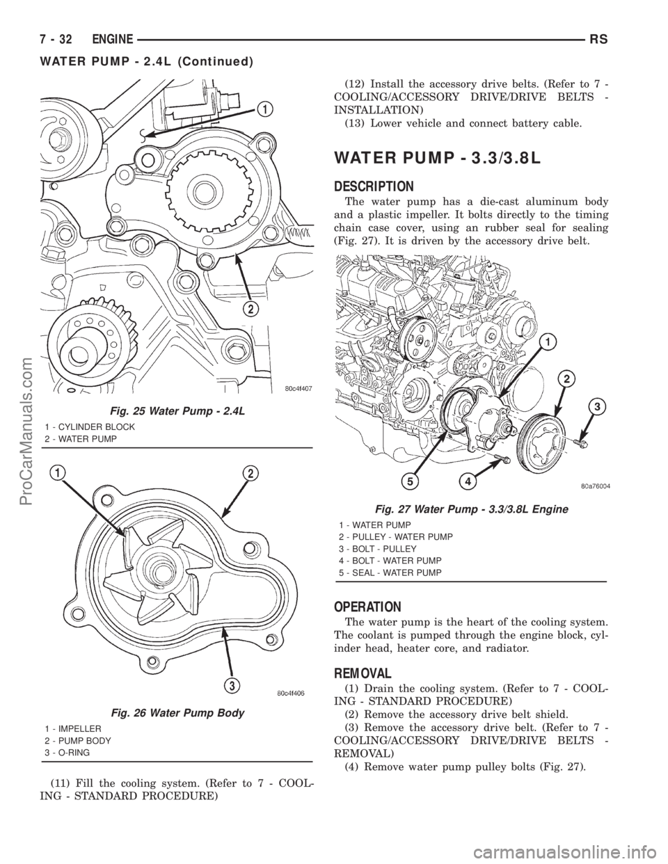
WATER PUMP - 3.3/3.8L
DESCRIPTION
The water pump has a die-cast aluminum body
and a plastic impeller. It bolts directly to the timing
chain case cover, using an rubber seal for sealing
(Fig. 27). It is driven by the accessory drive belt.
OPERATION
The water pump is the heart of the cooling system.
The coolant is pumped through the engine block, cyl-
inder head, heater core, and radiator.
REMOVAL
(1) Drain the cooling system. (Refer to 7 - COOL-
ING - STANDARD PROCEDURE)
(2) Remove the accessory drive belt shield.
(3) Remove the accessory drive belt. (Refer to 7 -
COOLING/ACCESSORY DRIVE/DRIVE BELTS -
REMOVAL)
(4) Remove water pump pulley bolts (Fig. 27).
Fig. 25 Water Pump - 2.4L
1 - CYLINDER BLOCK
2 - WATER PUMP
Fig. 26 Water Pump Body
1 - IMPELLER
2 - PUMP BODY
3 - O-RING
Fig. 27 Water Pump - 3.3/3.8L Engine
1 - WATER PUMP
2 - PULLEY - WATER PUMP
3 - BOLT - PULLEY
4 - BOLT - WATER PUMP
5 - SEAL - WATER PUMP
7 - 32 ENGINERS
WATER PUMP - 2.4L (Continued)
ProCarManuals.com
Page 301 of 2321
(2) Position the water pump pulley loosely between
pump housing and drive hub (Fig. 28).
(3) Install water pump and pulley to the timing
chain case cover (Fig. 27). Tighten water pump bolts
to 12 N´m (105 in. lbs.).
(4) Position pulley on water pump hub. Install
bolts and tighten to 30 N´m (250 in. lbs.) (Fig. 27).
(5) Rotate pump by hand to check for freedom of
movement.
(6) Install the accessory drive belt. (Refer to 7 -
COOLING/ACCESSORY DRIVE/DRIVE BELTS -
INSTALLATION)
(7) Install drive belt shield.
(8) Fill the cooling system. (Refer to 7 - COOLING
- STANDARD PROCEDURE)
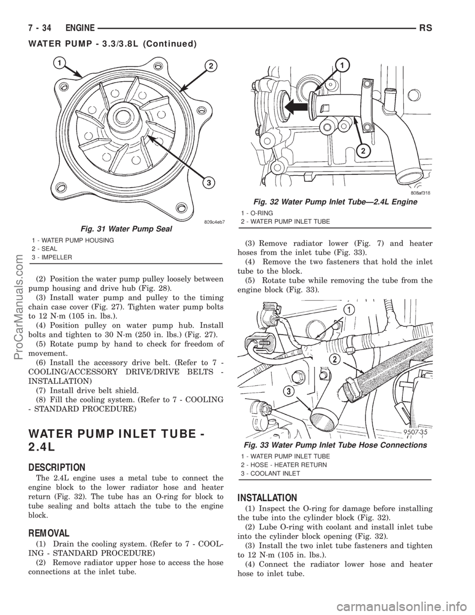
WATER PUMP INLET TUBE -
2.4L
DESCRIPTION
The 2.4L engine uses a metal tube to connect the
engine block to the lower radiator hose and heater
return (Fig. 32). The tube has an O-ring for block to
tube sealing and bolts attach the tube to the engine
block.
REMOVAL
(1) Drain the cooling system. (Refer to 7 - COOL-
ING - STANDARD PROCEDURE)
(2) Remove radiator upper hose to access the hose
connections at the inlet tube.(3) Remove radiator lower (Fig. 7) and heater
hoses from the inlet tube (Fig. 33).
(4) Remove the two fasteners that hold the inlet
tube to the block.
(5) Rotate tube while removing the tube from the
engine block (Fig. 33).
INSTALLATION
(1) Inspect the O-ring for damage before installing
the tube into the cylinder block (Fig. 32).
(2) Lube O-ring with coolant and install inlet tube
into the cylinder block opening (Fig. 32).
(3) Install the two inlet tube fasteners and tighten
to 12 N´m (105 in. lbs.).
(4) Connect the radiator lower hose and heater
hose to inlet tube.
Fig. 31 Water Pump Seal
1 - WATER PUMP HOUSING
2 - SEAL
3 - IMPELLER
Fig. 32 Water Pump Inlet TubeÐ2.4L Engine
1 - O-RING
2 - WATER PUMP INLET TUBE
Fig. 33 Water Pump Inlet Tube Hose Connections
1 - WATER PUMP INLET TUBE
2 - HOSE - HEATER RETURN
3 - COOLANT INLET
7 - 34 ENGINERS
WATER PUMP - 3.3/3.8L (Continued)
ProCarManuals.com
Page 302 of 2321
(5) Install the radiator upper hose.
(6) Fill the cooling system. (Refer to 7 - COOLING
- STANDARD PROCEDURE)
WATER PUMP INLET TUBE -
3.3/3.8L
REMOVAL
(1) Drain the cooling system. (Refer to 7 - COOL-
ING - STANDARD PROCEDURE)
(2) Raise vehicle on hoist and remove the belt
splash shield.
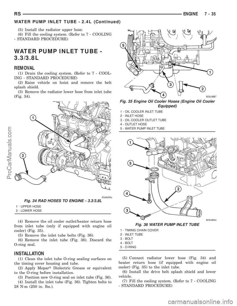
(3) Remove the radiator lower hose from inlet tube
(Fig. 34).
(4) Remove the oil cooler outlet/heater return hose
from inlet tube (only if equipped with engine oil
cooler) (Fig. 35).
(5) Remove the inlet tube bolts (Fig. 36).
(6) Remove the inlet tube (Fig. 36). Discard the
O-ring seal.
INSTALLATION
(1) Clean the inlet tube O-ring sealing surfaces on
the timing cover housing and tube.
(2) Apply MopartDielectric Grease or equivalent
to the O-ring before installation.
(3) Position new O-ring seal on inlet tube (Fig. 36).
(4) Install the inlet tube (Fig. 36). Tighten bolts to
28 N´m (250 in. lbs.).(5) Connect radiator lower hose (Fig. 34) and
heater return hose (if equipped with engine oil
cooler) (Fig. 35) to the inlet tube.
(6) Install the drive belt splash shield and lower
vehicle.
(7) Fill the cooling system. (Refer to 7 - COOLING
- STANDARD PROCEDURE)
Fig. 34 RAD HOSES TO ENGINE - 3.3/3.8L
1 - UPPER HOSE
2 - LOWER HOSE
Fig. 35 Engine Oil Cooler Hoses (Engine Oil Cooler
Equipped)
1 - OIL COOLER INLET TUBE
2 - INLET HOSE
3 - OIL COOLER OUTLET TUBE
4 - OUTLET HOSE
5 - WATER PUMP INLET TUBE
Fig. 36 WATER PUMP INLET TUBE
1 - TIMING CHAIN COVER
2 - INLET TUBE
3 - BOLT
4 - BOLT
5 - O-RING
RSENGINE7-35
WATER PUMP INLET TUBE - 2.4L (Continued)
ProCarManuals.com