2001 DODGE TOWN AND COUNTRY clock
[x] Cancel search: clockPage 72 of 2321
ASSEMBLY - STRUT ASSEMBLY
For the disassembly and assembly of the strut
assembly, use of Strut Spring Compressor, Pentastar
Service Equipment (PSE) tool W-7200, or the equiva-
lent, is recommended to compress the coil spring.
Follow the manufacturer's instructions closely.
NOTE: Coil Springs on this vehicle are side-ori-
ented. Springs on the left side of the vehicle have a
left-hand wind top-to-bottom while springs on the
right side have a right-hand wind top-to-bottom.
Left and right springs must not be interchanged.
NOTE: If the coil spring has been removed from the
spring compressor, proceed with the next step, oth-
erwise, proceed with step 5.
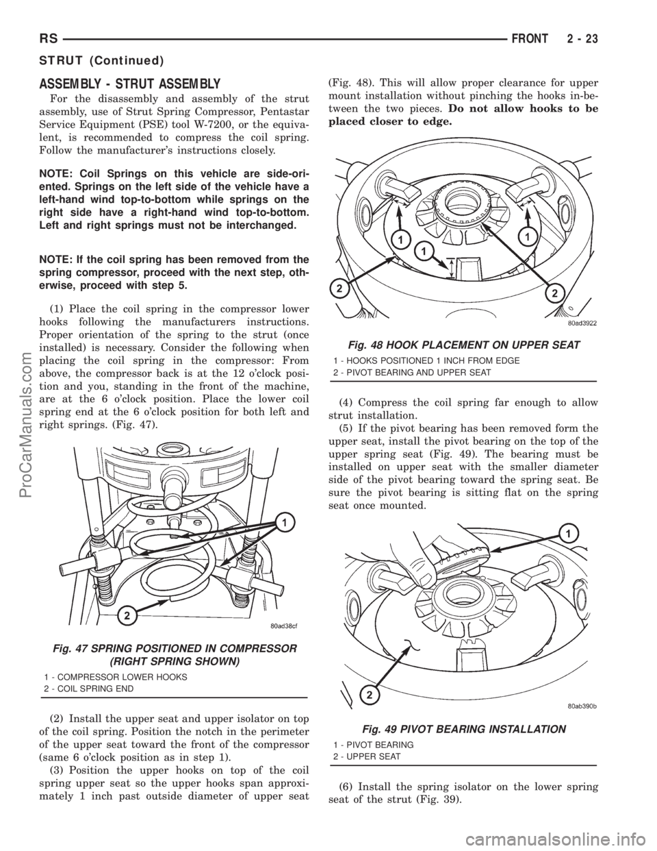
(1) Place the coil spring in the compressor lower
hooks following the manufacturers instructions.
Proper orientation of the spring to the strut (once
installed) is necessary. Consider the following when
placing the coil spring in the compressor: From
above, the compressor back is at the 12 o'clock posi-
tion and you, standing in the front of the machine,
are at the 6 o'clock position. Place the lower coil
spring end at the 6 o'clock position for both left and
right springs. (Fig. 47).
(2) Install the upper seat and upper isolator on top
of the coil spring. Position the notch in the perimeter
of the upper seat toward the front of the compressor
(same 6 o'clock position as in step 1).
(3) Position the upper hooks on top of the coil
spring upper seat so the upper hooks span approxi-
mately 1 inch past outside diameter of upper seat(Fig. 48). This will allow proper clearance for upper
mount installation without pinching the hooks in-be-
tween the two pieces.Do not allow hooks to be
placed closer to edge.
(4) Compress the coil spring far enough to allow
strut installation.
(5) If the pivot bearing has been removed form the
upper seat, install the pivot bearing on the top of the
upper spring seat (Fig. 49). The bearing must be
installed on upper seat with the smaller diameter
side of the pivot bearing toward the spring seat. Be
sure the pivot bearing is sitting flat on the spring
seat once mounted.
(6) Install the spring isolator on the lower spring
seat of the strut (Fig. 39).
Fig. 47 SPRING POSITIONED IN COMPRESSOR
(RIGHT SPRING SHOWN)
1 - COMPRESSOR LOWER HOOKS
2 - COIL SPRING END
Fig. 48 HOOK PLACEMENT ON UPPER SEAT
1 - HOOKS POSITIONED 1 INCH FROM EDGE
2 - PIVOT BEARING AND UPPER SEAT
Fig. 49 PIVOT BEARING INSTALLATION
1 - PIVOT BEARING
2 - UPPER SEAT
RSFRONT2-23
STRUT (Continued)
ProCarManuals.com
Page 73 of 2321
(7) Install the jounce bumper on the strut shaft
(Fig. 39). The jounce bumper is to be installed with
the small end pointing downward.
(8) Install the dust shield on the strut. Collapse
and stretch the dust shield down over the top of the
jounce bumper until the dust shield snaps into the
slot on the jounce bumper. The jounce bumper will be
at the top of the inner dust boot. Return the dust
shield to its fully extended length.
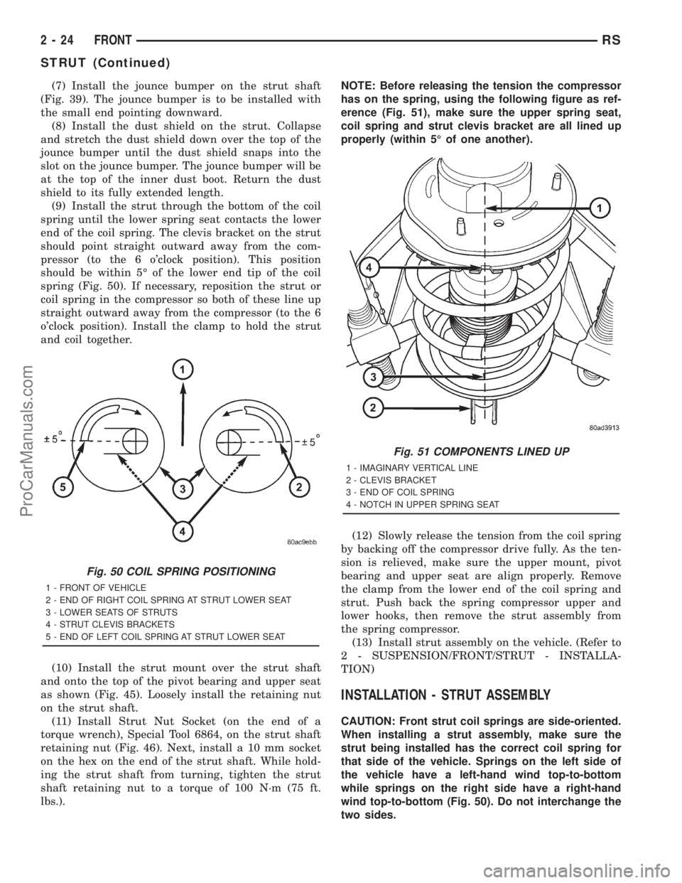
(9) Install the strut through the bottom of the coil
spring until the lower spring seat contacts the lower
end of the coil spring. The clevis bracket on the strut
should point straight outward away from the com-
pressor (to the 6 o'clock position). This position
should be within 5É of the lower end tip of the coil
spring (Fig. 50). If necessary, reposition the strut or
coil spring in the compressor so both of these line up
straight outward away from the compressor (to the 6
o'clock position). Install the clamp to hold the strut
and coil together.
(10) Install the strut mount over the strut shaft
and onto the top of the pivot bearing and upper seat
as shown (Fig. 45). Loosely install the retaining nut
on the strut shaft.
(11) Install Strut Nut Socket (on the end of a
torque wrench), Special Tool 6864, on the strut shaft
retaining nut (Fig. 46). Next, install a 10 mm socket
on the hex on the end of the strut shaft. While hold-
ing the strut shaft from turning, tighten the strut
shaft retaining nut to a torque of 100 N´m (75 ft.
lbs.).NOTE: Before releasing the tension the compressor
has on the spring, using the following figure as ref-
erence (Fig. 51), make sure the upper spring seat,
coil spring and strut clevis bracket are all lined up
properly (within 5É of one another).
(12) Slowly release the tension from the coil spring
by backing off the compressor drive fully. As the ten-
sion is relieved, make sure the upper mount, pivot
bearing and upper seat are align properly. Remove
the clamp from the lower end of the coil spring and
strut. Push back the spring compressor upper and
lower hooks, then remove the strut assembly from
the spring compressor.
(13) Install strut assembly on the vehicle. (Refer to
2 - SUSPENSION/FRONT/STRUT - INSTALLA-
TION)
INSTALLATION - STRUT ASSEMBLY
CAUTION: Front strut coil springs are side-oriented.
When installing a strut assembly, make sure the
strut being installed has the correct coil spring for
that side of the vehicle. Springs on the left side of
the vehicle have a left-hand wind top-to-bottom
while springs on the right side have a right-hand
wind top-to-bottom (Fig. 50). Do not interchange the
two sides.
Fig. 50 COIL SPRING POSITIONING
1 - FRONT OF VEHICLE
2 - END OF RIGHT COIL SPRING AT STRUT LOWER SEAT
3 - LOWER SEATS OF STRUTS
4 - STRUT CLEVIS BRACKETS
5 - END OF LEFT COIL SPRING AT STRUT LOWER SEAT
Fig. 51 COMPONENTS LINED UP
1 - IMAGINARY VERTICAL LINE
2 - CLEVIS BRACKET
3 - END OF COIL SPRING
4 - NOTCH IN UPPER SPRING SEAT
2 - 24 FRONTRS
STRUT (Continued)
ProCarManuals.com
Page 84 of 2321

(13) Install the spring washer (Fig. 18) on the stub
shaft of the outer C/V joint.
(14) Install the nut retainer and cotter pin (Fig.
19) on the stub shaft of the outer C/V joint.
(15) Install the wheel speed sensor on the hub/
bearing and adapter. Install the wheel speed sensor
attaching bolt (Fig. 20). Tighten the wheel speed sen-
sor attaching bolt to a torque of 12 N´m (105 in. lbs).
(16) Install wheel and tire.(17) Tighten the wheel mounting stud nuts in
proper sequence until all nuts are torqued to half
specification. Then repeat the tightening sequence to
the full specified torque of 135 N´m (100 ft. lbs.).
(18) Remove jackstands or lower hoist.
CAUTION: Before moving vehicle, pump the brake
pedal several times to insure the vehicle has a firm
brake pedal to adequately stop vehicle.
(19) Road test vehicle to ensure proper operation
of the brake system.
JOUNCE BUMPER
DESCRIPTION
There are two jounce bumpers used in the rear
suspension. One mounts to each frame rail above the
rear axle.
OPERATION
The jounce bumper limits suspension travel and
metal-to-metal contact of the rear axle with the
frame under full jounce conditions.
REMOVAL - AWD AND HEAVY DUTY
(1) Using slip-joint pliers grasp the base of the
jounce bumper. Turn the base counterclockwise (Fig.
21).
(2) Remove the jounce bumper from the frame rail.
REMOVAL - FRONT-WHEEL-DRIVE
(1) Remove the bolt attaching the jounce bumper
to frame rail (Fig. 22).
(2) Remove the jounce bumper from the frame rail.
Fig. 18 Spring Washer
1 - HUB NUT
2 - STUB SHAFT
3 - ROTOR
4 - SPRING WASHER
Fig. 19 Cotter Pin And Nut Retainer
1 - CALIPER
2 - COTTER PIN
3 - ROTOR
4 - NUT RETAINER
5 - OUTER C/V JOINT
Fig. 20 Wheel Speed Sensor
1 - MOUNTING BOLT
2 - WHEEL SPEED SENSOR
RSREAR2-35
HUB / BEARING (Continued)
ProCarManuals.com
Page 141 of 2321
ASSEMBLY
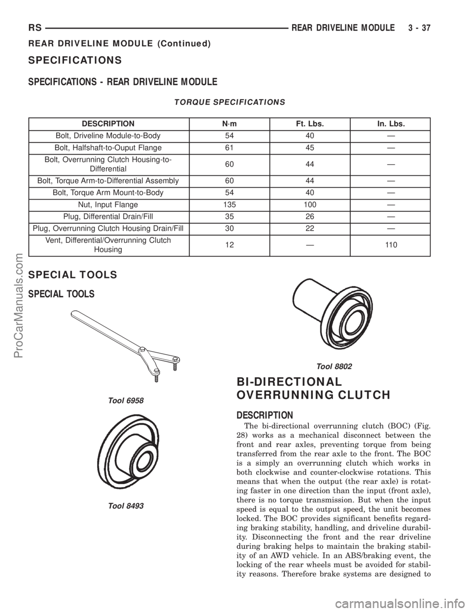
(1) Install output flange seals using tools C4171
and 8493 (Fig. 15).
(2) Install large overrunning clutch housing o-ring
to differential assembly (Fig. 14).
(3) Install shim to differential pinion shaft (Fig.
16).
(4) Install viscous coupler to differential pinion
shaft (Fig. 17).
(5) Install overrunning clutch assembly to viscous
coupler (Fig. 18).
(6) Install washer to overrunning clutch (Fig. 14).
(7) Install o-ring to overrunning clutch (Fig. 14).
(8) Align overrunning clutch ground tab to 12
o'clock position (Fig. 19).
(9) Install overrunning clutch housing into posi-
tion, making sure ground tab engages with notch in
housing (Fig. 20).
(10) Install and torque overrunning clutch hous-
ing-to-differential assembly bolts (Fig. 21) to 60 N´m
(44 ft. lbs.).
(11) Install input flange seal using tool 8802 (Fig.
22).
(12) Install flange/shield assembly (Fig. 23).
(13) Install input flange washer and nut. Using
tool 6958 (Fig. 24), torque nut to 135 N´m (100 ft.
lbs.).
(14) Install torque arm assembly into position.
Install and torque torque arm-to-differential assem-
bly bolts (Fig. 25) to 60 N´m (44 ft. lbs.).
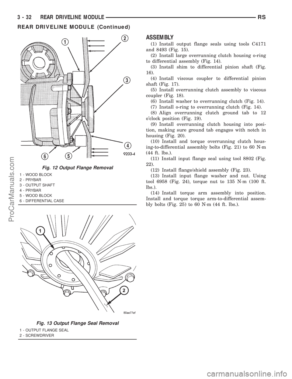
Fig. 12 Output Flange Removal
1 - WOOD BLOCK
2 - PRYBAR
3 - OUTPUT SHAFT
4 - PRYBAR
5 - WOOD BLOCK
6 - DIFFERENTIAL CASE
Fig. 13 Output Flange Seal Removal
1 - OUTPUT FLANGE SEAL
2 - SCREWDRIVER
3 - 32 REAR DRIVELINE MODULERS
REAR DRIVELINE MODULE (Continued)
ProCarManuals.com
Page 143 of 2321
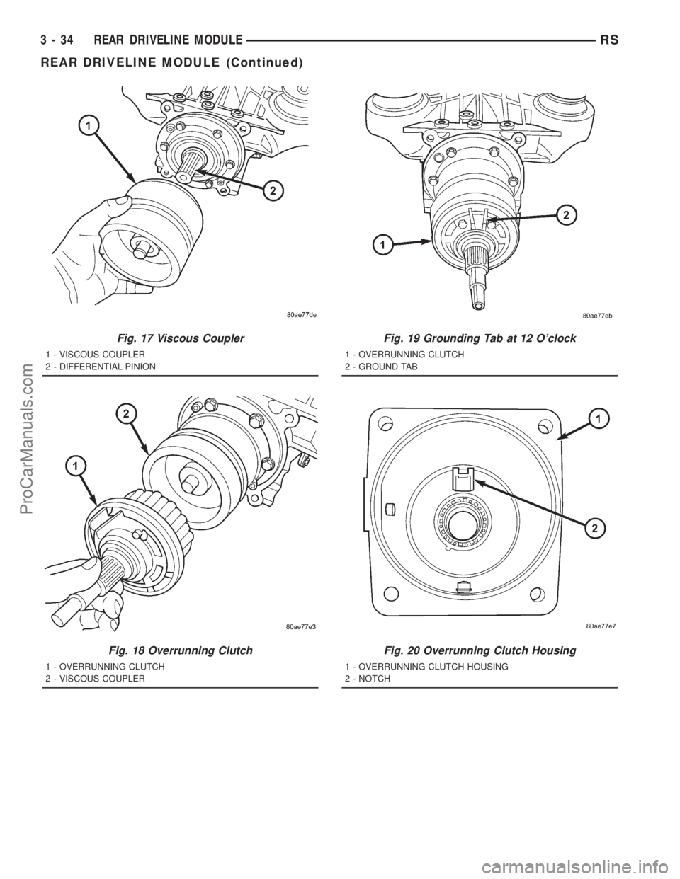
Fig. 17 Viscous Coupler
1 - VISCOUS COUPLER
2 - DIFFERENTIAL PINION
Fig. 18 Overrunning Clutch
1 - OVERRUNNING CLUTCH
2 - VISCOUS COUPLER
Fig. 19 Grounding Tab at 12 O'clock
1 - OVERRUNNING CLUTCH
2 - GROUND TAB
Fig. 20 Overrunning Clutch Housing
1 - OVERRUNNING CLUTCH HOUSING
2 - NOTCH
3 - 34 REAR DRIVELINE MODULERS
REAR DRIVELINE MODULE (Continued)
ProCarManuals.com
Page 146 of 2321
SPECIFICATIONS
SPECIFICATIONS - REAR DRIVELINE MODULE
TORQUE SPECIFICATIONS
DESCRIPTION N´m Ft. Lbs. In. Lbs.
Bolt, Driveline Module-to-Body 54 40 Ð
Bolt, Halfshaft-to-Ouput Flange 61 45 Ð
Bolt, Overrunning Clutch Housing-to-
Differential60 44 Ð
Bolt, Torque Arm-to-Differential Assembly 60 44 Ð
Bolt, Torque Arm Mount-to-Body 54 40 Ð
Nut, Input Flange 135 100 Ð
Plug, Differential Drain/Fill 35 26 Ð
Plug, Overrunning Clutch Housing Drain/Fill 30 22 Ð
Vent, Differential/Overrunning Clutch
Housing12 Ð 110
SPECIAL TOOLS
SPECIAL TOOLS
BI-DIRECTIONAL
OVERRUNNING CLUTCH
DESCRIPTION
The bi-directional overrunning clutch (BOC) (Fig.
28) works as a mechanical disconnect between the
front and rear axles, preventing torque from being
transferred from the rear axle to the front. The BOC
is a simply an overrunning clutch which works in
both clockwise and counter-clockwise rotations. This
means that when the output (the rear axle) is rotat-
ing faster in one direction than the input (front axle),
there is no torque transmission. But when the input
speed is equal to the output speed, the unit becomes
locked. The BOC provides significant benefits regard-
ing braking stability, handling, and driveline durabil-
ity. Disconnecting the front and the rear driveline
during braking helps to maintain the braking stabil-
ity of an AWD vehicle. In an ABS/braking event, the
locking of the rear wheels must be avoided for stabil-
ity reasons. Therefore brake systems are designed to
Tool 6958
Tool 8493
Tool 8802
RSREAR DRIVELINE MODULE3-37
REAR DRIVELINE MODULE (Continued)
ProCarManuals.com
Page 147 of 2321
lock the front wheels first. Any torque transfer from
the rear axle to the front axle disturbs the ABS/brak-
ing system and causes potential instabilities on a
slippery surface. The BOC de-couples the rear driv-
eline as soon the rear wheels begin to spin faster
than the front wheels (front wheels locked) in order
to provide increased braking stability. Furthermore
the BOC also reduces the likelihood of throttle off
over-steer during cornering. In a throttle off maneu-
ver, the BOC once again de-couples the rear driveline
forcing all the engine brake torque to the front
wheels. This eliminates the chance of lateral slip on
the rear axle and increases it on the front. The vehi-
cle will therefore tend to understeer, a situation
which is considered easier to manage in most circum-
stances. During this maneuver, and during the ABS
braking event, the BOC does not transmit torque
through to the rear wheels. The rear driveline mod-
ule, with the BOC, will perform the same as a front
wheel drive vehicle during these events. The gear
ratio offset between the front and rear differentials
force the BOC into the overrunning mode most of the
time. This allows BOC to significantly reduce the
rolling resistance of the vehicle, which improves fuel
consumption, allows the downsizing of the driveline
components, and prevents the PTU and propshaft
joints from overheating.
OPERATION
In order to achieve all-wheel drive operation in
reverse, the overrunning clutch locking functional
direction must be reversible. The bi-directional over-
running clutch (BOC) changes the operational mode
direction depending on the propeller shaft direction.
The propeller shaft rotates in the clockwise (when
viewed from the front) direction when the vehicle is
moving forward, which indexes the BOC to the for-
ward overrunning position. When the vehicle is in
reverse, the propeller shaft will rotate counter-clock-
wise and index the BOC to the reverse overrunning
position.
The BOC acts as a mechanical stator. It is active
(transmitting torque), or it is not active and in over-
running mode (not transmitting torque). This ªall or
nothingº approach to torque transfer would cause a
sudden application of all available power to the rear
wheels, which is not desirable. Therefore it is run in
series with a viscous coupler to smooth, dampen, and
limit the transmission of torque to the rear axle and
to prevent a step style torque input to the rear axle.
STEADY STATE, LOW TO MODERATE SPEED, NO
FRONT WHEEL SLIP, FORWARD DIRECTION
During normal driving conditions, (no wheel slip),
the inner shaft (front axle) and outer race (viscous
coupler) are running at different speeds due to the
different gear ratios between the front and rear dif-
ferentials. In this condition, the outer race is always
spinning faster (overdriving between 5-32 rpm) than
the inner shaft. When the BOC (Fig. 29) is running
under these conditions, at low vehicle speeds the
drag shoes and the cage keep the rollers up on the
left side (forward side) of the inner shaft flats. This is
what is known as ªoverrunning mode.º Notice that
when the clutch is in overrunning mode, the rollers
are spinning clockwise and with the outer race, thus
no torque is being transferred.
NOTE: Low speed, forward and reverse operation is
identical, just in opposite directions. (Fig. 29)
shows forward direction in reverse the rollers are
on the other side of the flats due to a reversal of
the cage force.
TRANSIENT CONDITION (BOC LOCKED), FRONT
WHEEL SLIP, FORWARD DIRECTION
When the front wheels lose traction and begin to
slip, the propeller shaft and rear axle pinion speed
difference decreases to zero. At this point the input
shaft (cam) becomes the driving member of the BOC
(Fig. 30), compressing the rollers against the outer
race. This locks the input shaft with the outer race
and transmits torque to the housing of the viscous
coupler, that in turn transmits torque to the rear
axle pinion. It should also be noted that when the
device is locked, the inner shaft and the outer race
are rotating at the same speed. The rollers are
pinched at this point and will stay locked until a
torque reversal (no front wheel slip) occurs. When
locked, the viscous coupler slips during the torque
transfer and the amount of torque transferred is
dependent on the coupling characteristic and the
amount of front wheel slip.
3 - 38 REAR DRIVELINE MODULERS
BI-DIRECTIONAL OVERRUNNING CLUTCH (Continued)
ProCarManuals.com
Page 225 of 2321
INSTALLATION - PARKING BRAKE CABLE
(LEFT REAR)
(1) Install the rear parking brake cable in the
brake support plate. Insert cable housing retainer
into brake support plate making certain that cable
housing retainer fingers lock the housing and
retainer firmly into place.
(2) Attach the parking brake cable onto the park
brake actuator lever.
(3) Install the brake shoes on the rear brake sup-
port plate. (Refer to 5 - BRAKES/HYDRAULIC/ME-
CHANICAL/BRAKE PADS/SHOES -
INSTALLATION).
(4) Insert cable housing retainer into body outrig-
ger bracket making certain that cable housing
retainer fingers lock the housing firmly into place.
(5) Connect rear parking brake cable to the equal-
izer bracket (Fig. 114).
(6) Install brake drum, and wheel and tire assem-
bly.
(7) Remove the locking pliers from the front park
brake cable. This will automatically adjust the park
brake cables.
(8) Apply and release park brake pedal 1 time.
This will seat the park brake cables.
ADJUSTMENT - CABLES
The park brake cables on this vehicle have an
automatic self adjuster built into the park brake
pedal mechanism. When the foot operated park brake
pedal is in its released (upward most) position, a
clock spring automatically adjusts the park brake
cables. The park brake cables are adjusted (ten-
sioned) just enough to remove all the slack from the
cables. The automatic adjuster system will not over
adjust the cables causing rear brake drag.
Due to the automatic adjust feature of the park
brake pedal, adjustment of the parking brake cables
on these vehicles relies on proper drum brake and
park brake shoe adjustment. (Refer to 5 - BRAKES/
HYDRAULIC/MECHANICAL/DRUM - ADJUST-
MENTS) and (Refer to 5 - BRAKES/PARKING
BRAKE/SHOES - ADJUSTMENTS).
When the park brake pedal is applied the self
adjuster is by-passed and the pedal operates nor-
mally to engage the park brakes.
When a service procedure needs to be performed on
the park brake pedal or the park brake cables, the
automatic self adjuster can be manually locked out
by the service technician.
5 - 66 BRAKES - BASERS
CABLES (Continued)
ProCarManuals.com