2001 DODGE TOWN AND COUNTRY mileage
[x] Cancel search: mileagePage 29 of 2321

every other interval on Schedule ± B (6,000 miles -
10 000 km).
²Check the engine coolant level, hoses, and
clamps.
EMISSION CONTROL SYSTEM MAINTENANCE
The scheduled emission maintenance listed inbold
typeon the Maintenance Schedules, must be done at
the mileage specified to assure the continued proper
functioning of the emission control system. These,
and all other maintenance services included in this
manual, should be done to provide the best vehicle
performance and reliability. More frequent mainte-
nance may be needed for vehicles in severe operating
conditions such as dusty areas and very short trip
driving.
DESCRIPTION - MAINTENANCE SCHEDULES
SCHEDULE±A±CHRYSLER TOWN AND
COUNTRY VEHICLES
7,500 Miles (12 000 km) or at 6 months
²Change the engine oil.
²Replace the engine oil filter.
15,000 Miles (24 000 km) or at 12 months
²Change the engine oil.
²Replace the engine oil filter.
22,500 Miles (36 000 km) or at 18 months
²Change the engine oil.
²Replace the engine oil filter.
²Inspect the brake linings.
30,000 Miles (48 000 km) or at 24 months
²Change the engine oil.
²Replace the engine oil filter.
²Replace the engine air cleaner element (fil-
ter).
²Inspect the tie rod ends and boot seals.
37,500 Miles (60 000 km) or at 30 months
²Change the engine oil.
²Replace the engine oil filter.
45,000 Miles (72 000 km) or at 36 months
²Change the engine oil.
²Replace the engine oil filter.
²Inspect the brake linings.
52,500 Miles (84 000 km) or at 42 months
²Change the engine oil.
²Replace the engine oil filter.
60,000 Miles (96 000 km) or at 48 months
²Change the engine oil.
²Replace the engine oil filter.
²Replace the engine air cleaner element (fil-
ter).
²Check the PCV valve and replace, if neces-
sary.*
²Inspect the serpentine drive belt, replace if nec-
essary.
²Inspect the tie rod ends and boot seals.
67,500 Miles (108 000 km) or at 54 months
²Change the engine oil.
²Replace the engine oil filter.
²Inspect the brake linings.
75,000 Miles (120 000 km) or at 60 months
²Change the engine oil.
²Replace the engine oil filter.
²Inspect the serpentine drive belt and replace if
necessary. This maintenance is not required if the
belt was previously replaced.
²Flush and replace engine coolant at 60 months.
82,500 Miles (132 000 km) or at 66 months
²Change the engine oil.
²Replace the engine oil filter.
90,000 Miles (144 000 km) or at 72 months
²Change the engine oil.
²Replace the engine oil filter.
²Replace the engine air cleaner element (fil-
ter).
²Check the PCV valve and replace, if neces-
sary. Not required if previously changed.*
²Inspect the serpentine drive belt, replace if nec-
essary. This maintenance is not required if the belt
was previously replaced.
²Inspect the tie rod ends and boot seals.
²Inspect the brake linings.
97,500 Miles (156 000 km) or at 78 months
²Change the engine oil.
²Replace the engine oil filter.
100,000 Miles (160,000 km)
²Replace the spark plugs.
²Replace the ignition cables.
²Flush and replace engine coolant at 60 months
or 100,000 miles (160,000 km).
105,000 Miles (168 000 km) or at 84 months
²Change the engine oil.
²Replace the engine oil filter.
²Inspect the serpentine drive belt and replace if
necessary. This maintenance is not required if the
belt was previously replaced.
0 - 8 LUBRICATION & MAINTENANCERS
MAINTENANCE SCHEDULES (Continued)
ProCarManuals.com
Page 44 of 2321

FLUID FILL/CHECK
LOCATIONS
DESCRIPTION
The fluid check/fill points and lubrication locations
are located in each applicable service manual section.
MAINTENANCE SCHEDULES
MAINTENANCE SCHEDULES - DIESEL ENGINE
There are two maintenance schedules that show
proper service for the vehicle.
First is ScheduleªAº. It lists all the scheduled
maintenance to be performed under ªnormalº operat-
ing conditions.
Second is ScheduleªBº. It is a schedule for vehi-
cles that are operated under the conditions listed at
the beginning of the schedule.
Use the schedule that best describes the driving
conditions.
Where time and mileage are listed, follow the
interval that occurs first.
At Each Stop for Fuel
²Check the engine oil level, add as required.
²Check the windshield washer solvent and add if
required.
Once a Month
²Check the tire pressure and look for unusual
wear or damage.
²Inspect the battery and clean and tighten termi-
nals as required.
²Check the fluid levels of coolant reservoir, brake
master cylinder, power steering and transaxle and
add as needed.
²Check all lights and all other electrical items for
correct operation.
²Check the rubber seals on each side of the radi-
ator for proper fit.
At Each Oil Change
²Replace the engine oil filter at each oil change.
²Inspect exhaust system.
²Inspect brake hoses
²Inspect the CV joints and front suspension com-
ponents
²Rotate the tires at each oil change interval
shown on schedule ªAº 20 000 km or every other
interval shown on schedule ªBº 20 000 km.
²Check the coolant level, hoses, and clamps.
²Inspect brake linings, hoses and calipers.
²Inspect engine accessory drive belts.
²Inspect for presence of water in fuel filter/water
separator, drain if necessary.
SCHEDULE ªAº
20 000 km (12 000 miles)
²Change engine oil. (1)
²Replace engine oil filter.
²Inspect air filter element. Replace as necessary.
40 000 km (24 000 Miles)
²Change engine oil. (1)
²Replace engine oil filter.
²Replace air filter element.
²Replace fuel filter/water separator element. (2)
²Check alignment.
60 000 km (37 000 Miles)
²Change engine oil. (1)
²Replace engine oil filter.
²Inspect air filter element. Replace as necessary.
80 000 km (49 000 Miles)
²Change engine oil. (1)
²Replace engine oil filter.
²Replace air filter element.
²Replace fuel filter/water separator element. (2)
²Check alignment.
100 000 km (62 000 Miles)
²Change engine oil. (1)
²Replace engine oil filter.
²Inspect air filter element. Replace as necessary.
120 000 km (75 000 Miles)
²Change engine oil. (1)
²Replace engine oil filter.
²Replace air filter element.
²Replace fuel filter/water separator element. (2)
²Check alignment.
140 000 km (86 000 miles)
²Change engine oil. (1)
²Replace engine oil filter.
²Inspect air filter element. Replace as necessary.
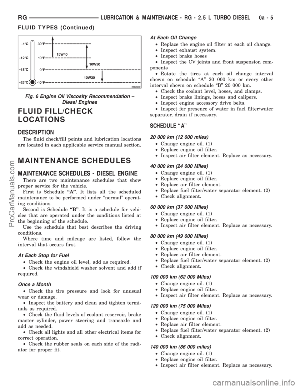
Fig. 6 Engine Oil Viscosity Recommendation ±
Diesel Engines
RGLUBRICATION & MAINTENANCE - RG - 2.5 L TURBO DIESEL0a-5
FLUID TYPES (Continued)
ProCarManuals.com
Page 289 of 2321

DIAGNOSIS AND TESTING - ENGINE COOLANT
THERMOSTAT
The thermostat is operated by a wax filled cham-
ber (pellet) which is sealed. When heated coolant
reaches a predetermined temperature the wax pellet
expands enough to overcome the closing spring and
water pump pressure, which forces the valve to open.
Coolant leakage into the pellet will cause a thermo-
stat to fail open. Do not attempt to free up a thermo-
stat with a screwdriver.
Thermostat diagnostics is included in powertrain
control module's (PCM) programing for on-board
diagnosis. The malfunction indicator light (MIL) will
illuminate and a diagnostic trouble code (DTC) will
be set when an ªopen too soonº condition occurs. Do
not change a thermostat for lack of heater perfor-
mance or temperature gauge position, unless a DTC
is present. For other probable causes, (Refer to 7 -
COOLING/ENGINE - DIAGNOSIS AND TESTING) .
Thermostat failing shut is the normal long term
mode of failure, and normally, only on high mileage
vehicles. The temperature gauge will indicate this
(Refer to 7 - COOLING/ENGINE - DIAGNOSIS AND
TESTING) .
ENGINE COOLANT
THERMOSTAT - 2.4L
REMOVAL
(1) Drain cooling system below the thermostat
level. (Refer to 7 - COOLING - STANDARD PROCE-
DURE)
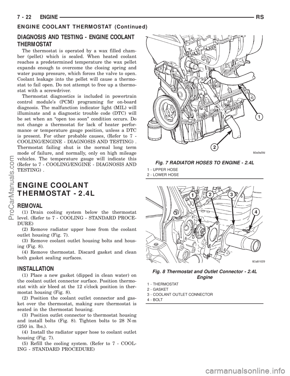
(2) Remove radiator upper hose from the coolant
outlet housing (Fig. 7).
(3) Remove coolant outlet housing bolts and hous-
ing (Fig. 8).
(4) Remove thermostat. Discard gasket and clean
both gasket sealing surfaces.
INSTALLATION
(1) Place a new gasket (dipped in clean water) on
the coolant outlet connector surface. Position thermo-
stat with air bleed at the 12 o'clock position in ther-
mostat housing (Fig. 8).
(2) Position the coolant outlet connector and gas-
ket over the thermostat, making sure thermostat is
seated in the thermostat housing.
(3) Position outlet connector to thermostat housing
and install bolts (Fig. 8). Tighten bolts to 28 N´m
(250 in. lbs.).
(4) Install the radiator upper hose to coolant outlet
housing (Fig. 7).
(5) Refill the cooling system. (Refer to 7 - COOL-
ING - STANDARD PROCEDURE)
Fig. 7 RADIATOR HOSES TO ENGINE - 2.4L
1 - UPPER HOSE
2 - LOWER HOSE
Fig. 8 Thermostat and Outlet Connector - 2.4L
Engine
1 - THERMOSTAT
2 - GASKET
3 - COOLANT OUTLET CONNECTOR
4 - BOLT
7 - 22 ENGINERS
ENGINE COOLANT THERMOSTAT (Continued)
ProCarManuals.com
Page 310 of 2321

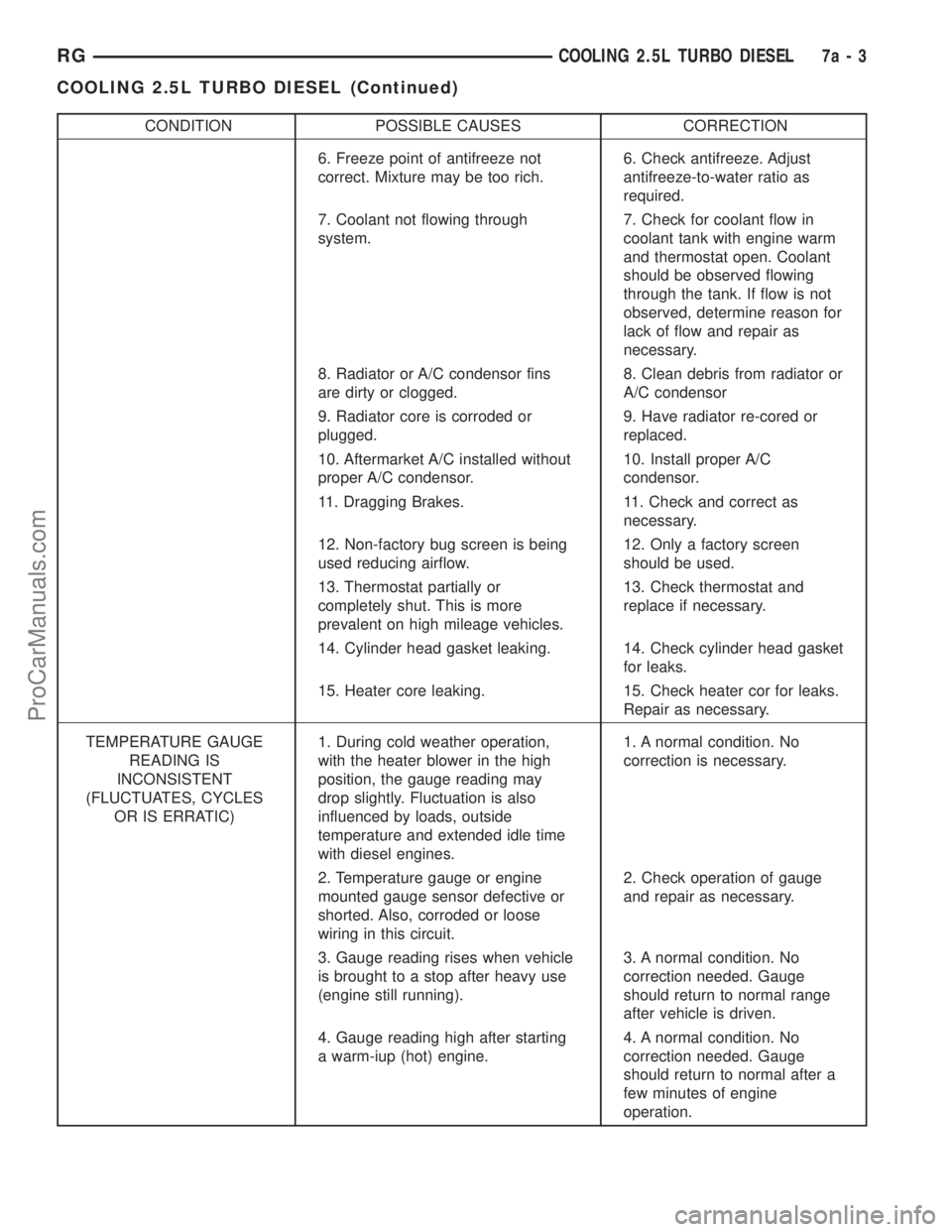
CONDITION POSSIBLE CAUSES CORRECTION
6. Freeze point of antifreeze not
correct. Mixture may be too rich.6. Check antifreeze. Adjust
antifreeze-to-water ratio as
required.
7. Coolant not flowing through
system.7. Check for coolant flow in
coolant tank with engine warm
and thermostat open. Coolant
should be observed flowing
through the tank. If flow is not
observed, determine reason for
lack of flow and repair as
necessary.
8. Radiator or A/C condensor fins
are dirty or clogged.8. Clean debris from radiator or
A/C condensor
9. Radiator core is corroded or
plugged.9. Have radiator re-cored or
replaced.
10. Aftermarket A/C installed without
proper A/C condensor.10. Install proper A/C
condensor.
11. Dragging Brakes. 11. Check and correct as
necessary.
12. Non-factory bug screen is being
used reducing airflow.12. Only a factory screen
should be used.
13. Thermostat partially or
completely shut. This is more
prevalent on high mileage vehicles.13. Check thermostat and
replace if necessary.
14. Cylinder head gasket leaking. 14. Check cylinder head gasket
for leaks.
15. Heater core leaking. 15. Check heater cor for leaks.
Repair as necessary.
TEMPERATURE GAUGE
READING IS
INCONSISTENT
(FLUCTUATES, CYCLES
OR IS ERRATIC)1. During cold weather operation,
with the heater blower in the high
position, the gauge reading may
drop slightly. Fluctuation is also
influenced by loads, outside
temperature and extended idle time
with diesel engines.1. A normal condition. No
correction is necessary.
2. Temperature gauge or engine
mounted gauge sensor defective or
shorted. Also, corroded or loose
wiring in this circuit.2. Check operation of gauge
and repair as necessary.
3. Gauge reading rises when vehicle
is brought to a stop after heavy use
(engine still running).3. A normal condition. No
correction needed. Gauge
should return to normal range
after vehicle is driven.
4. Gauge reading high after starting
a warm-iup (hot) engine.4. A normal condition. No
correction needed. Gauge
should return to normal after a
few minutes of engine
operation.
RGCOOLING 2.5L TURBO DIESEL7a-3
COOLING 2.5L TURBO DIESEL (Continued)
ProCarManuals.com
Page 366 of 2321

²Throttle Position Sensor
²Torque Management Input (From TCM)
²Transaxle Control Module (TCM)
²Transaxle Gear Engagement (From TCM)
²Vehicle Speed (from transmission control mod-
ule)
NOTE: PCM Outputs:
²Air Conditioning Clutch Relay
²Automatic Shut Down (ASD) and Fuel Pump
Relays
²Data Link Connector (PCI and SCI Transmit)
²Double Start Override
²EGR Solenoid
²Fuel Injectors
²Generator Field
²High Speed Fan Relay
²Idle Air Control Motor
²Ignition Coils
²Leak Detection Pump
²Low Speed Fan Relay
²MTV Actuator
²Proportional Purge Solenoid
²SRV Valve
²Speed Control Relay
²Speed Control Vent Relay
²Speed Control Vacuum Relay
²8 Volt Output
²5 Volt Output
Based on inputs it receives, the powertrain control
module (PCM) adjusts fuel injector pulse width, idle
speed, ignition timing, and canister purge operation.
The PCM regulates the cooling fans, air conditioning
and speed control systems. The PCM changes gener-
ator charge rate by adjusting the generator field.
The PCM adjusts injector pulse width (air-fuel
ratio) based on the following inputs.
²Battery Voltage
²Intake Air Temperature Sensor
²Engine Coolant Temperature
²Engine Speed (crankshaft position sensor)
²Exhaust Gas Oxygen Content (heated oxygen
sensors)
²Manifold Absolute Pressure
²Throttle Position
The PCM adjusts engine idle speed through the
idle air control motor based on the following inputs.
²Brake Switch
²Engine Coolant Temperature
²Engine Speed (crankshaft position sensor)
²Park/Neutral (transmission gear selection)
²Transaxle Gear Engagement
²Throttle Position
²Vehicle Speed (from Transmission Control Mod-
ule)The PCM adjusts ignition timing based on the fol-
lowing inputs.
²Intake Air Temperature
²Engine Coolant Temperature
²Engine Speed (crankshaft position sensor)
²Knock Sensor
²Manifold Absolute Pressure
²Park/Neutral (transmission gear selection)
²Transaxle Gear Engagement
²Throttle Position
The automatic shut down (ASD) and fuel pump
relays are mounted externally, but turned on and off
by the powertrain control module through the same
circuit.
The camshaft and crankshaft signals are sent to
the powertrain control module. If the PCM does not
receive both signals within approximately one second
of engine cranking, it deactivates the ASD and fuel
pump relays. When these relays are deactivated,
power is shut off to the fuel injectors, ignition coils,
fuel pump and the heating element in each oxygen
sensor.
The PCM contains a voltage converter that
changes battery voltage to a regulated 8.0 volts. The
8.0 volts power the camshaft position sensor, crank-
shaft position sensor and vehicle speed sensor. The
PCM also provides a 5.0 volts supply for the engine
coolant temperature sensor, intake air temperature
sensor, manifold absolute pressure sensor and throt-
tle position sensor.
The PCM engine control strategy prevents reduced
idle speeds until after the engine operates for 320 km
(200 miles). If the PCM is replaced after 320 km (200
miles) of usage, update the mileage in new PCM. Use
the DRB scan tool to change the mileage in the PCM.
Refer to the appropriate Powertrain Diagnostic Man-
ual and the DRB scan tool.
DIAGNOSTIC TROUBLE CODE
DESCRIPTION
A Diagnostic Trouble Code (DTC) indicates the
PCM has recognized an abnormal condition in the
system.
Remember that DTC's are the results of a sys-
tem or circuit failure, but do not directly iden-
tify the failed component or components.
NOTE: For a list of DTC's, refer to the charts in this
section.
RSELECTRONIC CONTROL MODULES8E-9
POWERTRAIN CONTROL MODULE (Continued)
ProCarManuals.com
Page 375 of 2321

(M) Check Engine Lamp (MIL) will illuminate during engine operation if this Diagnostic Trouble Code was recorded.
(G) Generator Lamp Illuminated
GENERIC SCAN
TOOL CODEDRB SCAN TOOL DISPLAY DESCRIPTION OF DIAGNOSTIC TROUBLE CODE
P1682 (G) Charging System Voltage Too Low Battery voltage sense input below target charging voltage
during engine operation and no significant change in voltage
detected during active test of generator output circuit.
P1683 SPD CTRL PWR Relay; or S/C 12v
Driver CKTAn open or shorted condition detected in the speed control
servo power control circuit. (SBECII: ext relay).
P1684 Battery Loss In The Last 50 Starts The battery has been disconnected within the last 50 starts.
P1685 Skim Invalid Key The engine controler has received an invalid key from the
SKIM.
P1686 No SKIM BUS Messages Received No CCD/J1850 messages received from the Smart Key
Immobilizer Module (SKIM).
P1687 No MIC BUS Message No CCD/J1850 messages received from the Mechanical
Instrument Cluster (MIC) module.
P1693 DTC Detected in Companion Module A fault has been generated in the companion engine control
module.
P1694 Fault In Companion Module No CCD/J1850 messages received from the powertrain
control module-Aisin transmission.
P1695 No CCD/J1850 Message From Body
Control ModuleNo CCD/J1850 messages received from the body control
module.
P1696 (M) PCM Failure EEPROM Write Denied Unsuccessful attempt to write to an EEPROM location by the
control module.
P1697 (M) PCM Failure SRI Mile Not Stored Unsuccessful attempt to update Service Reminder Indicator
(SRI or EMR) mileage in the control module EEPROM.
P1698 (M) No CCD/J1850 Message From TCM No CCD/J1850 messages received from the electronic
transmission control module (EATX) or the Aisin transmission
controller.
P1719 Skip Shift Solenoid Circuit An open or shorted condition detected in the transmission
2-3 gear lock-out solenoid control circuit.
P1756 GOV Press Not Equal to Target @
15-20 PSIThe requested pressure and the actual pressure are not
within a tolerance band for the Governor Control System
which is used to regulate governor pressure to control shifts
for 1st, 2nd, and 3rd gear. (Mid Pressure Malfunction)
P1757 GOV Press Not Equal to Target @
15-20 PSIThe requested pressure and the actual pressure are not
within a tolerance band for the Governor Control System
which is used to regulate governor pressure to control shifts
for 1st, 2nd, and 3rd gear (Zero Pressure Malfunction)
P1762 Gov Press Sen Offset Volts Too Low
or HighThe Governor Pressure Sensor input is greater than a
calibration limit or is less than a calibration limit for 3
consecutive park/neutral calibrations.
P1763 Governor Pressure Sensor Volts Too
HiThe Governor Pressure Sensor input is above an acceptable
voltage level.
P1764 Governor Pressure Sensor Volts Too
LowThe Governor Pressure Sensor input is below an acceptable
voltage level.
P1765 Trans 12 Volt Supply Relay CTRL
CircuitAn open or shorted condition is detected in the Transmission
Relay control circuit. This relay supplies power to the TCC>
P1899 (M) P/N Switch Stuck in Park or in Gear Incorrect input state detected for the Park/Neutral switch.
8E - 18 ELECTRONIC CONTROL MODULESRS
POWERTRAIN CONTROL MODULE (Continued)
ProCarManuals.com
Page 378 of 2321

²Fuel system monitor
²EGR monitor
²Purge system monitor
²All inputs monitored for proper voltage range.
²All monitored components (refer to the Emission
section for On-Board Diagnostics).
The PCM compares the upstream and downstream
heated oxygen sensor inputs to measure catalytic
convertor efficiency. If the catalyst efficiency drops
below the minimum acceptable percentage, the PCM
stores a diagnostic trouble code in memory.
During certain idle conditions, the PCM may enter
a variable idle speed strategy. During variable idle
speed strategy the PCM adjusts engine speed based
on the following inputs.
²A/C sense
²Battery voltage
²Battery temperature
²Engine coolant temperature
²Engine run time
²Inlet/Intake air temperature
²Vehicle mileage
ACCELERATION MODE
This is a CLOSED LOOP mode. The PCM recog-
nizes an abrupt increase in Throttle Position sensor
output voltage or MAP sensor output voltage as a
demand for increased engine output and vehicle
acceleration. The PCM increases injector pulse width
in response to increased fuel demand.
DECELERATION MODE
This is a CLOSED LOOP mode. During decelera-
tion the following inputs are received by the PCM:
²A/C sense
²Battery voltage
²Inlet/Intake air temperature
²Engine coolant temperature
²Crankshaft position (engine speed)
²Exhaust gas oxygen content (upstream heated
oxygen sensor)
²Knock sensor
²Manifold absolute pressure
²Throttle position
²IAC motor control changes in response to MAP
sensor feedback
The PCM may receive a closed throttle input from
the Throttle Position Sensor (TPS) when it senses an
abrupt decrease in manifold pressure. This indicates
a hard deceleration. In response, the PCM may
momentarily turn off the injectors. This helps
improve fuel economy, emissions and engine braking.
WIDE-OPEN-THROTTLE MODE
This is an OPEN LOOP mode. During wide-open-
throttle operation, the following inputs are used by
the PCM:
²Inlet/Intake air temperature
²Engine coolant temperature
²Engine speed
²Knock sensor
²Manifold absolute pressure
²Throttle position
When the PCM senses a wide-open-throttle condi-
tion through the Throttle Position Sensor (TPS) it de-
energizes the A/C compressor clutch relay. This
disables the air conditioning system.
The PCM does not monitor the heated oxygen sen-
sor inputs during wide-open-throttle operation except
for downstream heated oxygen sensor and both
shorted diagnostics. The PCM adjusts injector pulse
width to supply a predetermined amount of addi-
tional fuel.
IGNITION SWITCH OFF MODE
When the operator turns the ignition switch to the
OFF position, the following occurs:
²All outputs are turned off, unless 02 Heater
Monitor test is being run. Refer to the Emission sec-
tion for On-Board Diagnostics.
²No inputs are monitored except for the heated
oxygen sensors. The PCM monitors the heating ele-
ments in the oxygen sensors and then shuts down.
STANDARD PROCEDURES - OBTAINING
DIAGNOSTIC TROUBLE CODES
BULB CHECK
Each time the ignition key is turned to the ON
position, the malfunction indicator (check engine)
lamp on the instrument panel should illuminate for
approximately 2 seconds then go out. This is done for
a bulb check. When the key is in the power on, but
engine off position, the MIL will remain illuminated
for regulatory purposes.
OBTAINING DTC'S USING DRB SCAN TOOL
(1) Connect the DRB scan tool to the data link
(diagnostic) connector. This connector is located in
the passenger compartment; at the lower edge of
instrument panel; near the steering column.
(2) Turn the ignition switch on and access the
ªRead Faultº screen.
(3) Record all the DTC's and ªfreeze frameº infor-
mation shown on the DRB scan tool.
RSELECTRONIC CONTROL MODULES8E-21
POWERTRAIN CONTROL MODULE (Continued)
ProCarManuals.com
Page 385 of 2321

STANDARD PROCEDURE - TCC BREAK-IN
VIEW/RESTART PROCEDURE
The Transmission Control Module (TCM) employs
a strategy which modifies torque converter clutch
(TCC) operation. This strategy conditions the torque
converter clutch disc for optimum converter clutch
engagement and feel throughout the life of the trans-
axle. The cycle inhibits FEMCC until six hours of
PEMCC operation have taken place, or the vehicle
has been driven 6,035 km (3750 miles). The cycle
automatically terminates when either the time or
mileage has been achieved, however, the mileage
may vary slightly from vehicle to vehicle.
The TCC break-in cycle must be restarted using
the DRB Scan Tool, and upon:
²Replacement of TCM on vehicle with less than
6,035 km (3750 miles) or less than 6 hours of
PEMCC operation
²Replacement of torque converter assembly at
any vehicle mileage
NOTE: Failure to restart the TCC Break-In Cycle
upon TCM replacement in vehicles with less than
six hours of PEMCC or less than 6,035 km (3750
miles), or upon torque converter replacement at any
mileage, may result in vehicle shudder during cer-
tain operating conditions.
Procedure
The DRB Scan Tool is required to view and/or
restart the TCC Break-In cycle.
(1) Connect the DRB Scan Tool to the vehicle diag-
nostic connector.
(2) Navigate to ªTCC Break-Inº via Transmission/
Transmission Control Module/Miscellaneous.
(3) View or Start TCC Break-In as prompted by
DRB menu.
REMOVAL
NOTE: If transmission control module is being
replaced with a new or replacement unit, the Pinion
Factor and Quick Learn procedures must be per-
formed. (Refer to 8 - ELECTRICAL/ELECTRONIC
CONTROL MODULES/TRANSMISSION CONTROL
MODULE - STANDARD PROCEDURE) (Refer to 8 -
ELECTRICAL/ELECTRONIC CONTROL MODULES/
TRANSMISSION CONTROL MODULE - STANDARD
PROCEDURE) If vehicle has less than 6,035 km
(3750 miles), the Torque Converter Clutch (TCC)
Break-In Strategy reset procedure must also be per-
formed. (Refer to 8 - ELECTRICAL/ELECTRONIC
CONTROL MODULES/TRANSMISSION CONTROL
MODULE - STANDARD PROCEDURE)(1) Disconnect battery negative cable.
(2) Raise vehicle on hoist.
(3) Remove left front tire/wheel assembly.
(4) Pull back splash shield to gain access to TCM
location.
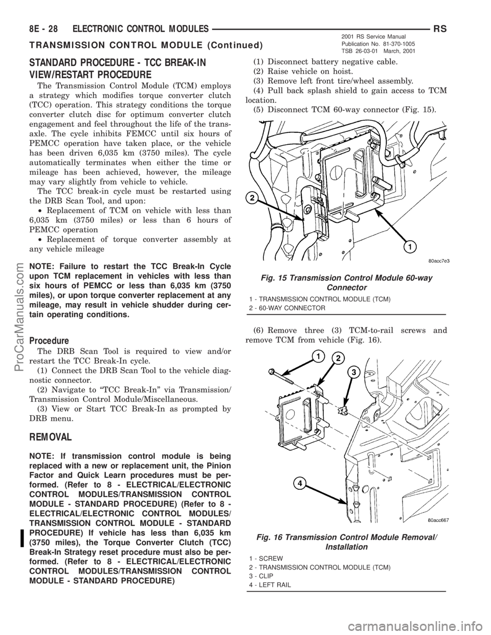
(5) Disconnect TCM 60-way connector (Fig. 15).
(6) Remove three (3) TCM-to-rail screws and
remove TCM from vehicle (Fig. 16).
Fig. 15 Transmission Control Module 60-way
Connector
1 - TRANSMISSION CONTROL MODULE (TCM)
2 - 60-WAY CONNECTOR
Fig. 16 Transmission Control Module Removal/
Installation
1 - SCREW
2 - TRANSMISSION CONTROL MODULE (TCM)
3 - CLIP
4 - LEFT RAIL
8E - 28 ELECTRONIC CONTROL MODULESRS
TRANSMISSION CONTROL MODULE (Continued)
2001 RS Service Manual
Publication No. 81-370-1005
TSB 26-03-01 March, 2001
ProCarManuals.com