2001 DODGE TOWN AND COUNTRY airbag disable
[x] Cancel search: airbag disablePage 352 of 2321
CHIME/BUZZER
TABLE OF CONTENTS
page page
CHIME/BUZZER
DESCRIPTION............................1
OPERATION.............................1
DIAGNOSIS AND TESTING..................1
CHIME SYSTEM.........................1
DOME LAMP ON CHIME..................2
ENGINE TEMPERATURE CRITICAL CHIME....2EXTERIOR LAMPS ON CHIME..............2
KEY-IN IGNITION CHIME..................2
LOW OIL PRESSURE CHIME...............2
SEAT BELT CHIME.......................3
SEAT BELT LAMP.......................3
TURN SIGNAL ON CHIME.................3
WARNING LAMP ANNOUNCEMENT CHIME....3
CHIME/BUZZER
DESCRIPTION
WARNING: ON VEHICLES EQUIPPED WITH AIR-
BAGS, DISABLE THE AIRBAG SYSTEM BEFORE
ATTEMPTING ANY STEERING WHEEL, STEERING
COLUMN, OR INSTRUMENT PANEL COMPONENT
DIAGNOSIS OR SERVICE. DISCONNECT AND ISO-
LATE THE BATTERY NEGATIVE (GROUND) CABLE,
THEN WAIT TWO MINUTES FOR THE AIRBAG SYS-
TEM CAPACITOR TO DISCHARGE BEFORE PER-
FORMING FURTHER DIAGNOSIS OR SERVICE. THIS
IS THE ONLY SURE WAY TO DISABLE THE AIRBAG
SYSTEM. FAILURE TO TAKE THE PROPER PRE-
CAUTIONS COULD RESULT IN ACCIDENTAL AIR-
BAG DEPLOYMENT AND POSSIBLE PERSONAL
INJURY.
The chime/buzzer system provides the driver with
warning chimes for:
²Seat Belt
²Exterior Lamps ON
²Key-In Ignition
²Engine Temperature Critical
²Turn Signals ON
²Dome Lamp ON
²Low Oil Pressure
²High Speed Warning
²Warning Lamp Announcement
²Key-In Accessory
OPERATION
The Chime/Buzzer Warning System is diagnosed
using a DRBIIItscan tool. Refer to the proper Body
Diagnostic Procedures Manual.
DIAGNOSIS AND TESTING - CHIME SYSTEM
NO TONE WHEN IGNITION SWITCH IS TURNED ON
AND DRIVER'S SEAT BELT IS NOT BUCKLED.
(1) Using a DRBIIItscan tool, actuate chime
(BCM actuates).
(2) Using a voltmeter, check for voltage:
(a) BCM has two battery feeds at pin 1 and pin
5 of the 6±way connector.
(b) Pin 5 of the (BX2) 32 way connector of the
BCM for ignition feed.
(c) Check voltage (PX2) connector, pin 34 for 12v.
(d) If voltage OK, go to step Step 3
(e) If NO voltage repair as necessary. Refer to
the appropriate wiring information. The wiring
information includes wiring diagrams, proper wire
and connector repair procedures, further details on
wire harness routing and retention, as well as pin-
out and location views for the various wire harness
connectors, splices and grounds.
(3) Check driver's seat belt buckle switch input
(form ORC) for a closed circuit when not buckled. If
input not seen, look for open in wiring or switch. The
switch is grounded when belt is not buckled.
(4) Verify PCI data bus communication between
ORC and BCM.
NO FASTEN SEAT BELT LAMP WHEN IGNITION
SWITCH IS TURNED ON.
(1) Check for burned out lamp.
(2) Using a voltmeter check for voltage at the clus-
ter conncctor:
(a) Pin 2 of the mechanical instrument cluster
for battery feed.
(b) Pin 11 of the mechanical instrument cluster
for ignition voltage.
(3) Repair as necessary.
RSCHIME/BUZZER8B-1
ProCarManuals.com
Page 562 of 2321
POWER SEATS
TABLE OF CONTENTS
page page
POWER SEATS
DESCRIPTION...........................49
OPERATION.............................50
DIAGNOSIS AND TESTING.................51
POWER SEAT SYSTEM..................51
MEMORY SYSTEM......................51
DRIVER SEAT SWITCH
DESCRIPTION...........................52
OPERATION.............................52
DIAGNOSIS AND TESTING.................53
DRIVER SEAT SWITCH..................53
REMOVAL..............................53
INSTALLATION...........................54
MEMORY SET SWITCH
DESCRIPTION...........................54
OPERATION.............................54
DIAGNOSIS AND TESTING.................54
MEMORY SWITCH......................54
REMOVAL..............................54
INSTALLATION...........................54PASSENGER SEAT SWITCH
DESCRIPTION...........................55
OPERATION.............................55
DIAGNOSIS AND TESTING.................55
PASSENGER SEAT SWITCH..............55
REMOVAL..............................56
INSTALLATION...........................56
RECLINER MOTOR
DESCRIPTION...........................56
OPERATION.............................56
DIAGNOSIS AND TESTING.................57
POWER SEAT RECLINER................57
POWER SEAT TRACK
DESCRIPTION...........................58
OPERATION.............................58
DIAGNOSIS AND TESTING.................58
POWER SEAT TRACK...................58
REMOVAL..............................59
INSTALLATION...........................59
POWER SEATS
DESCRIPTION - POWER SEAT SYSTEM
The power seat system option allows the driver
and front seat passenger to electrically adjust their
seating positions for optimum control and comfort
using the power seat switches located on the out-
board seat cushion side shield of each front seat. The
power seat system receives battery current through a
40 amp fuse in the Intelligent Power Module and a
30 amp circuit breaker under the seat so that the
power seats remain operational, regardless of the
ignition switch position.
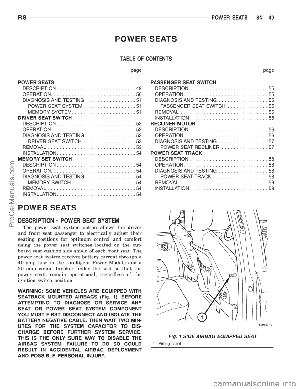
WARNING: SOME VEHICLES ARE EQUIPPED WITH
SEATBACK MOUNTED AIRBAGS (Fig. 1). BEFORE
ATTEMPTING TO DIAGNOSE OR SERVICE ANY
SEAT OR POWER SEAT SYSTEM COMPONENT
YOU MUST FIRST DISCONNECT AND ISOLATE THE
BATTERY NEGATIVE CABLE. THEN WAIT TWO MIN-
UTES FOR THE SYSTEM CAPACITOR TO DIS-
CHARGE BEFORE FURTHER SYSTEM SERVICE.
THIS IS THE ONLY SURE WAY TO DISABLE THE
AIRBAG SYSTEM. FAILURE TO DO SO COULD
RESULT IN ACCIDENTAL AIRBAG DEPLOYMENT
AND POSSIBLE PERSONAL INJURY.
Fig. 1 SIDE AIRBAG EQUIPPED SEAT
1 - Airbag Label
RSPOWER SEATS8N-49
ProCarManuals.com
Page 564 of 2321
trically and independently using the separate power
seat switches found on the outboard seat cushion
side shield of each front seat. See the owner's manual
in the vehicle glove box for more information on the
features, use and operation of the power seat system.
OPERATION - MEMORY SYSTEM
The Memory Seat/Mirror Module (MSMM) will
drive a maximum of 2 motors at a time in a given
direction. If conflicting directions are requested, the
priority for response will be as follows:
²Seat Track Rearward
²Seat Front Down
²Seat Rear Down
²Recliner Rearward
²Seat Track Forward
²Seat Front Up
²Seat Rear Up
²Recliner Forward
The inputs from these switches to the MSMM is a
current limited battery source fed by the MSMM.
This protects the MSMM printed circuit board traces
from acting as fuses. All of these switch contact
inputs to the MSMM are normally closed to ground,
except when actuated.
Soft stops are incorporated to prevent the motor
from being driven into a stall. Should the seat have
restricted travel, refer to Resetting Soft Stops in this
section.
See the owner's manual in the vehicle glove box for
more information on the features, use and operation
of the memory system. For diagnosis of the MSM, the
PCI data bus, or the other electronic modules on the
PCI data bus that provide inputs and outputs for the
memory system, the use of a DRBtscan tool and the
proper Diagnostic Procedures manual are recom-
mended.
ELECTRONIC VEHICLE INFORMATION CENTER
The Electronic Vehicle Information Center (EVIC)
serves as the user interface for the memory system.
It displays memory system status messages and pro-
vides the user with the means for enabling and dis-
abling the many customer programmable features
available on the vehicle, including those for the mem-
ory system.
See the owner's manual in the vehicle glove box for
more information on the features, use and operation
of the EVIC. Refer toElectronic Vehicle Informa-
tion Centerin Overhead Console Systems for more
information on the EVIC.
DIAGNOSIS AND TESTING - POWER SEAT
SYSTEM
Following are tests that will help to diagnose the
hard wired components and circuits of the power seatsystem. However, if the vehicle is also equipped with
the optional memory system, these tests may not
prove conclusive in the diagnosis of the driver side
power seat. In order to obtain conclusive testing of
the driver side power seat with the memory system
option, the Programmable Communications Interface
(PCI) data bus network and all of the electronic mod-
ules that provide inputs to, or receive outputs from
the memory system components must be checked.
The most reliable, efficient, and accurate means to
diagnose the driver side power seat with the memory
system option requires the use of a DRBtscan tool
and the proper Diagnostic Procedures manual. The
DRBtscan tool can provide confirmation that the
PCI data bus is functional, that all of the electronic
modules are sending and receiving the proper mes-
sages on the PCI data bus, and that the memory sys-
tem is receiving the proper hard wired inputs and
relaying the proper hard wired outputs to perform its
driver side power seat functions.
WARNING: SOME VEHICLES ARE EQUIPPED WITH
SEATBACK MOUNTED AIRBAGS (Fig. 1). BEFORE
ATTEMPTING TO DIAGNOSE OR SERVICE ANY
SEAT OR POWER SEAT SYSTEM COMPONENT
YOU MUST FIRST DISCONNECT AND ISOLATE THE
BATTERY NEGATIVE CABLE. THEN WAIT TWO MIN-
UTES FOR THE SYSTEM CAPACITOR TO DIS-
CHARGE BEFORE FURTHER SYSTEM SERVICE.
THIS IS THE ONLY SURE WAY TO DISABLE THE
AIRBAG SYSTEM. FAILURE TO DO SO COULD
RESULT IN ACCIDENTAL AIRBAG DEPLOYMENT
AND POSSIBLE PERSONAL INJURY.
Before any testing of the power seat system is
attempted, the battery should be fully-charged and
all of the power seat system wire harness connections
and pins cleaned and tightened to ensure proper cir-
cuit continuity and ground paths. For complete cir-
cuit diagrams, refer toPower Seatin Wiring
Diagrams.
With the dome lamp on, apply the power seat
switch in the direction of the failure. If the dome
lamp dims, the seat may be jamming. Check under
and behind the seat for binding or obstructions. If
the dome lamp does not dim, proceed with testing of
the individual components and circuits.
DIAGNOSIS AND TESTING - MEMORY SYSTEM
CHECK AND RESET SOFT STOPS
To check and reset the power memory seat soft
stops, use the power seat control switches to move
the seat in one direction to the end of travel, allow a
couple of seconds before re-energizing the seat in the
same direction until it stops and for three additional
seconds after it stops. (The amount the seat moved
RSPOWER SEATS8N-51
POWER SEATS (Continued)
ProCarManuals.com
Page 571 of 2321
POWER SEAT TRACK
DESCRIPTION
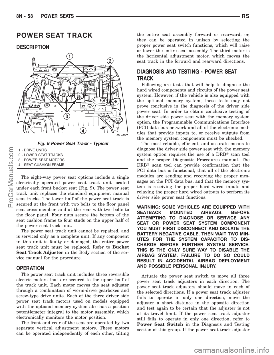
The eight-way power seat options include a single
electrically operated power seat track unit located
under each front bucket seat (Fig. 9). The power seat
track unit replaces the standard equipment manual
seat tracks. The lower half of the power seat track is
secured at the front with two bolts to the floor panel
seat cross member, and at the rear with two bolts to
the floor panel. Four nuts secure the bottom of the
seat cushion frame to four studs on the upper half of
the power seat track unit.
The power seat track unit cannot be repaired, and
is serviced only as a complete unit. If any component
in this unit is faulty or damaged, the entire power
seat track unit must be replaced. Refer toBucket
Seat Track Adjusterin the Body section of the ser-
vice manual for the procedure.
OPERATION
The power seat track unit includes three reversible
electric motors that are secured to the upper half of
the track unit. Each motor moves the seat adjuster
through a combination of worm-drive gearboxes and
screw-type drive units. Each of the three driver side
power seat track motors used on models equipped
with the optional memory system also has a position
potentiometer integral to the motor assembly, which
electronically monitors the motor position.
The front and rear of the seat are operated by two
separate vertical adjustment motors. These motors
can be operated independently of each other, tiltingthe entire seat assembly forward or rearward; or,
they can be operated in unison by selecting the
proper power seat switch functions, which will raise
or lower the entire seat assembly. The third motor is
the horizontal adjustment motor, which moves the
seat track in the forward and rearward directions.
DIAGNOSIS AND TESTING - POWER SEAT
TRACK
Following are tests that will help to diagnose the
hard wired components and circuits of the power seat
system. However, if the vehicle is also equipped with
the optional memory system, these tests may not
prove conclusive in the diagnosis of the driver side
power seat. In order to obtain conclusive testing of
the driver side power seat with the memory system
option, the Programmable Communications Interface
(PCI) data bus network and all of the electronic mod-
ules that provide inputs to, or receive outputs from
the memory system components must be checked.
The most reliable, efficient, and accurate means to
diagnose the driver side power seat with the memory
system option requires the use of a DRBtscan tool
and the proper Diagnostic Procedures manual. The
DRBtscan tool can provide confirmation that the
PCI data bus is functional, that all of the electronic
modules are sending and receiving the proper mes-
sages on the PCI data bus, and that the memory sys-
tem is receiving the proper hard wired inputs and
relaying the proper hard wired outputs to perform its
driver side power seat functions.
WARNING: SOME VEHICLES ARE EQUIPPED WITH
SEATBACK MOUNTED AIRBAGS. BEFORE
ATTEMPTING TO DIAGNOSE OR SERVICE ANY
SEAT OR POWER SEAT SYSTEM COMPONENT
YOU MUST FIRST DISCONNECT AND ISOLATE THE
BATTERY NEGATIVE CABLE. THEN WAIT TWO MIN-
UTES FOR THE SYSTEM CAPACITOR TO DIS-
CHARGE BEFORE FURTHER SYSTEM SERVICE.
THIS IS THE ONLY SURE WAY TO DISABLE THE
AIRBAG SYSTEM. FAILURE TO DO SO COULD
RESULT IN ACCIDENTAL AIRBAG DEPLOYMENT
AND POSSIBLE PERSONAL INJURY.
Actuate the power seat switch to move all three
power seat track adjusters in each direction. The
power seat track adjusters should move in each of
the selected directions. If a power seat track adjuster
fails to operate in only one direction, move the
adjuster a short distance in the opposite direction
and test again to be certain that the adjuster is not
at its travel limit. If the power seat track adjuster
still fails to operate in only one direction, refer to
Power Seat Switchin the Diagnosis and Testing
section of this group. If the power seat track adjuster
Fig. 9 Power Seat Track - Typical
1 - DRIVE UNITS
2 - LOWER SEAT TRACKS
3 - POWER SEAT MOTORS
4 - SEAT CUSHION FRAME
8N - 58 POWER SEATSRS
ProCarManuals.com
Page 572 of 2321
fails to operate in more than one direction, perform
the following tests. For complete circuit diagrams,
refer toPower Seatin Wiring Diagrams.
(1) Check the power seat circuit breaker under the
seat. If OK, go to Step 2. If not OK, replace the
faulty power seat circuit breaker.
(2) Check for battery voltage at the power seat cir-
cuit breaker under the seat. If OK, go to Step 3. If
not OK, repair the open fused B(+) circuit to the fuse
in the Intelligent Power Module as required.
(3) Remove the outboard seat cushion side shield
from the seat. Disconnect the seat wire harness con-
nector from the power seat switch connector recepta-
cle. Check for battery voltage at the fused B(+)
circuit cavity of the power seat wire harness connec-
tor for the power seat switch. If OK, go to Step 4. If
not OK, repair the open fused B(+) circuit to the
power seat circuit breaker under the seat as
required.
(4) Check for continuity between the ground cir-
cuit cavity of the power seat wire harness connector
for the power seat switch and a good ground. There
should be continuity. If OK, go to Step 5. If not OK,
repair the open ground circuit to ground as required.
(5) Test the power seat switch. Refer toPower
Seat Switchin the Diagnosis and Testing section of
this group. If the switch tests OK, test the circuits of
the power seat wire harness between the inoperative
power seat track adjuster motor and the power seat
switch for shorts or opens. If the circuits check OK,
replace the faulty power seat track unit. If the cir-
cuits are not OK, repair the power seat wire harness
as required.
REMOVAL
WARNING: SOME VEHICLES ARE EQUIPPED WITH
SEATBACK MOUNTED AIRBAGS. BEFORE
ATTEMPTING TO DIAGNOSE OR SERVICE ANY
SEAT OR POWER SEAT SYSTEM COMPONENT
YOU MUST FIRST DISCONNECT AND ISOLATE THE
BATTERY NEGATIVE CABLE. THEN WAIT TWO MIN-
UTES FOR THE SYSTEM CAPACITOR TO DIS-
CHARGE BEFORE FURTHER SYSTEM SERVICE.
THIS IS THE ONLY SURE WAY TO DISABLE THE
AIRBAG SYSTEM. FAILURE TO DO SO COULD
RESULT IN ACCIDENTAL AIRBAG DEPLOYMENT
AND POSSIBLE PERSONAL INJURY.(1) Remove the appropriate seat from the vehicle.
Refer to Body for the procedure.
(2) Remove two seat back mounting bolts and also
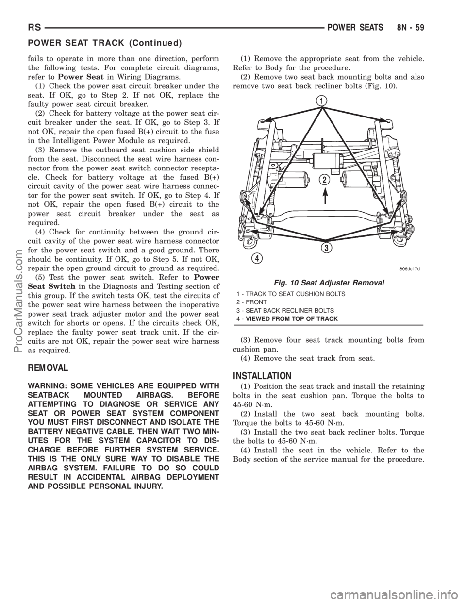
remove two seat back recliner bolts (Fig. 10).
(3) Remove four seat track mounting bolts from
cushion pan.
(4) Remove the seat track from seat.
INSTALLATION
(1) Position the seat track and install the retaining
bolts in the seat cushion pan. Torque the bolts to
45-60 N´m.
(2) Install the two seat back mounting bolts.
Torque the bolts to 45-60 N´m.
(3) Install the two seat back recliner bolts. Torque
the bolts to 45-60 N´m.
(4) Install the seat in the vehicle. Refer to the
Body section of the service manual for the procedure.
Fig. 10 Seat Adjuster Removal
1 - TRACK TO SEAT CUSHION BOLTS
2 - FRONT
3 - SEAT BACK RECLINER BOLTS
4-VIEWED FROM TOP OF TRACK
RSPOWER SEATS8N-59
POWER SEAT TRACK (Continued)
ProCarManuals.com
Page 581 of 2321
RESTRAINTS
DESCRIPTION - SIDE IMPACT AIRBAG
SYSTEM
Vehicles equipped with the Side Impact Airbag
System utilize two airbags mounted to each front
seat back frame. This system is designed to protect
occupants in the event of a side impact collision. The
individual seat airbags are not serviceable. If
deployed or defective, the entire seat back assembly
must be replaced.
OPERATION - SIDE IMPACT AIRBAG SYSTEM
The Side Impact Airbag Control Module (SIACM)
controls the seat back mounted airbags. If the
SIACM determines the impact is severe enough, the
appropriate airbag will inflate, tearing open the front
seat back trim cover protecting the passengers. Once
a seat back mounted airbag has been deployed, the
complete seat back assembly and all damaged parts
must be replaced.
WARNINGS
WARNING: THIS SYSTEM IS A SENSITIVE, COM-
PLEX ELECTRO±MECHANICAL UNIT. DISCONNECT
AND ISOLATE THE BATTERY NEGATIVE CABLE
BEFORE BEGINNING AIRBAG SYSTEM COMPO-
NENT REMOVAL OR INSTALLATION PROCEDURES.
THIS WILL DISABLE THE AIRBAG SYSTEM. FAIL-
URE TO DISCONNECT THE BATTERY COULD
RESULT IN ACCIDENTAL AIRBAG DEPLOYMENT
AND POSSIBLE PERSONAL INJURY.
ALLOW SYSTEM CAPACITOR TO DISCHARGE FOR
TWO MINUTES BEFORE REMOVING AIRBAG COM-
PONENTS.
DO NOT PLACE AN INTACT UNDEPLOYED AIRBAG
FACE DOWN ON A SOLID SURFACE, THE AIRBAG
WILL PROPEL INTO THE AIR IF ACCIDENTALLY
DEPLOYED AND COULD RESULT IN PERSONAL
INJURY. WHEN CARRYING OR HANDLING AN
UNDEPLOYED AIRBAG MODULE, THE TRIM SIDEOF THE AIRBAG SHOULD BE POINTING AWAY
FROM THE BODY TO MINIMIZE POSSIBILITY OF
INJURY IF ACCIDENTAL DEPLOYMENT OCCURS.
REPLACE AIRBAG SYSTEM COMPONENTS WITH
MOPARž REPLACEMENT PARTS. SUBSTITUTE
PARTS MAY APPEAR INTERCHANGEABLE, BUT
INTERNAL DIFFERENCES MAY RESULT IN INFE-
RIOR OCCUPANT PROTECTION.
WEAR SAFETY GLASSES, RUBBER GLOVES, AND
LONG SLEEVED CLOTHING WHEN CLEANING
POWDER RESIDUE FROM VEHICLE AFTER AIRBAG
DEPLOYMENT. SODIUM HYDROXIDE POWDER
RESIDUE EMITTED FROM A DEPLOYED AIRBAG
CAN CAUSE SKIN IRRITATION. FLUSH AFFECTED
AREA WITH COOL WATER IF IRRITATION IS EXPE-
RIENCED. IF NASAL OR THROAT IRRITATION IS
EXPERIENCED, EXIT THE VEHICLE FOR FRESH AIR
UNTIL THE IRRITATION CEASES. IF IRRITATION
CONTINUES, SEE A PHYSICIAN.
DO NOT USE A REPLACEMENT AIRBAG THAT IS
NOT IN THE ORIGINAL PACKAGING, IMPROPER
DEPLOYMENT AND PERSONAL INJURY CAN
RESULT.
THE FACTORY INSTALLED FASTENERS, SCREWS
AND BOLTS USED TO FASTEN AIRBAG COMPO-
NENTS HAVE A SPECIAL COATING AND ARE SPE-
CIFICALLY DESIGNED FOR THE AIRBAG SYSTEM.
DO NOT USE SUBSTITUTE FASTENERS, USE ONLY
ORIGINAL EQUIPMENT FASTENERS LISTED IN THE
PARTS CATALOG WHEN FASTENER REPLACE-
MENT IS REQUIRED.
CAUTION:
Deployed Front Air Bags may or may not have live
pyrotechnic material within the air bag inflator. Do
not dispose of 2001 Model Year Driver and Passen-
ger Airbags unless you are sure of complete
deployment. Please refer to the Hazardous Sub-
stance Control System for Proper Disposal. Dispose
of deployed air bags in a manner consistent with
state, provincial, local, and federal regulations.
8O - 2 RESTRAINTSRS
ProCarManuals.com
Page 1467 of 2321
COLUMN
TABLE OF CONTENTS
page page
COLUMN
DESCRIPTION...........................10
WARNING..............................10
DIAGNOSIS AND TESTING.................12
STEERING COLUMN....................12
REMOVAL..............................12
INSTALLATION...........................13
SPECIFICATIONS........................14
KEY/LOCK CYLINDER
DESCRIPTION...........................14OPERATION.............................14
REMOVAL..............................14
INSTALLATION...........................14
GEAR SHIFT LEVER
REMOVAL..............................15
INSTALLATION...........................15
SHROUD
REMOVAL..............................16
INSTALLATION...........................16
COLUMN
DESCRIPTION - STEERING COLUMN
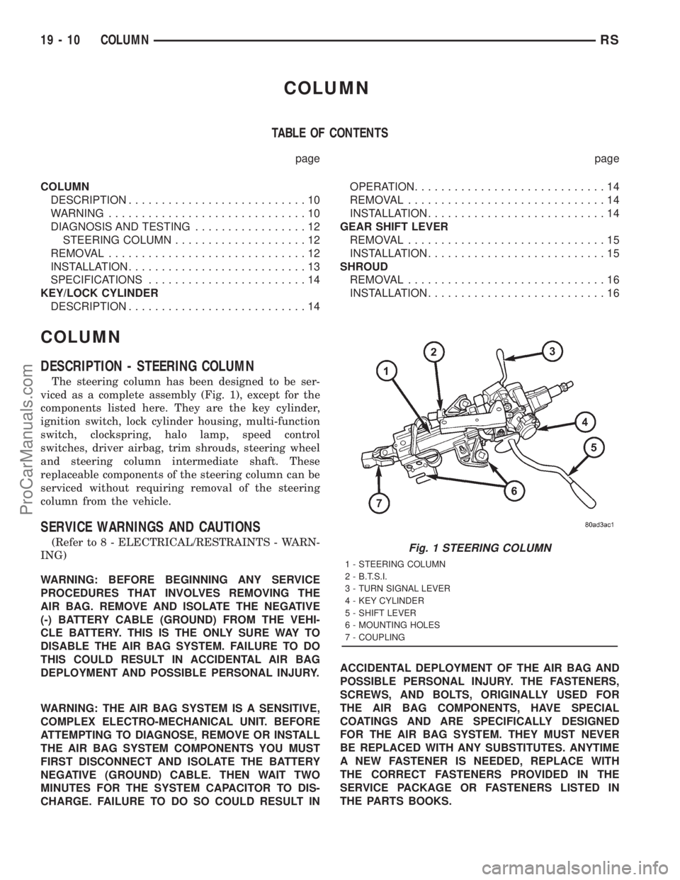
The steering column has been designed to be ser-
viced as a complete assembly (Fig. 1), except for the
components listed here. They are the key cylinder,
ignition switch, lock cylinder housing, multi-function
switch, clockspring, halo lamp, speed control
switches, driver airbag, trim shrouds, steering wheel
and steering column intermediate shaft. These
replaceable components of the steering column can be
serviced without requiring removal of the steering
column from the vehicle.
SERVICE WARNINGS AND CAUTIONS
(Refer to 8 - ELECTRICAL/RESTRAINTS - WARN-
ING)
WARNING: BEFORE BEGINNING ANY SERVICE
PROCEDURES THAT INVOLVES REMOVING THE
AIR BAG. REMOVE AND ISOLATE THE NEGATIVE
(-) BATTERY CABLE (GROUND) FROM THE VEHI-
CLE BATTERY. THIS IS THE ONLY SURE WAY TO
DISABLE THE AIR BAG SYSTEM. FAILURE TO DO
THIS COULD RESULT IN ACCIDENTAL AIR BAG
DEPLOYMENT AND POSSIBLE PERSONAL INJURY.
WARNING: THE AIR BAG SYSTEM IS A SENSITIVE,
COMPLEX ELECTRO-MECHANICAL UNIT. BEFORE
ATTEMPTING TO DIAGNOSE, REMOVE OR INSTALL
THE AIR BAG SYSTEM COMPONENTS YOU MUST
FIRST DISCONNECT AND ISOLATE THE BATTERY
NEGATIVE (GROUND) CABLE. THEN WAIT TWO
MINUTES FOR THE SYSTEM CAPACITOR TO DIS-
CHARGE. FAILURE TO DO SO COULD RESULT INACCIDENTAL DEPLOYMENT OF THE AIR BAG AND
POSSIBLE PERSONAL INJURY. THE FASTENERS,
SCREWS, AND BOLTS, ORIGINALLY USED FOR
THE AIR BAG COMPONENTS, HAVE SPECIAL
COATINGS AND ARE SPECIFICALLY DESIGNED
FOR THE AIR BAG SYSTEM. THEY MUST NEVER
BE REPLACED WITH ANY SUBSTITUTES. ANYTIME
A NEW FASTENER IS NEEDED, REPLACE WITH
THE CORRECT FASTENERS PROVIDED IN THE
SERVICE PACKAGE OR FASTENERS LISTED IN
THE PARTS BOOKS.Fig. 1 STEERING COLUMN
1 - STEERING COLUMN
2 - B.T.S.I.
3 - TURN SIGNAL LEVER
4 - KEY CYLINDER
5 - SHIFT LEVER
6 - MOUNTING HOLES
7 - COUPLING
19 - 10 COLUMNRS
ProCarManuals.com
Page 2172 of 2321
(3) The calibration procedure should take less than
three minutes to complete for the manual heater-A/C
control, and less than twenty seconds for the ATC
heater-A/C control. When the LEDs or graphics stop
flashing, the calibration procedure is complete.
(4) If the LEDs or graphics continue to flash
beyond the normal three minute (manual) or twenty
second (ATC) calibration time, it indicates that the
heater-A/C control has detected a failure and a Diag-
nostic Trouble Code (DTC) has been set. Use a
DRBIIItscan tool to perform further diagnosis. Refer
to the appropriate diagnostic information. The LEDs
or graphics will continue to flash even after the igni-
tion switch is cycled Off and On, until a successful
calibration is completed or until the vehicle has been
driven about 5 kilometers (3 miles).
REMOVAL
WARNING: ON VEHICLES EQUIPPED WITH AIR-
BAGS, DISABLE THE AIRBAG SYSTEM BEFORE
ATTEMPTING ANY STEERING WHEEL, STEERING
COLUMN, OR INSTRUMENT PANEL COMPONENT
DIAGNOSIS OR SERVICE. DISCONNECT AND ISO-
LATE THE BATTERY NEGATIVE (GROUND) CABLE,
THEN WAIT TWO MINUTES FOR THE AIRBAG SYS-
TEM CAPACITOR TO DISCHARGE BEFORE PER-
FORMING FURTHER DIAGNOSIS OR SERVICE. THIS
IS THE ONLY SURE WAY TO DISABLE THE AIRBAG
SYSTEM. FAILURE TO TAKE THE PROPER PRE-
CAUTIONS COULD RESULT IN ACCIDENTAL AIR-
BAG DEPLOYMENT AND POSSIBLE PERSONAL
INJURY.
(1) Disconnect and isolate the battery negative
cable.
(2) Remove the center bezel from the instrument
panel. (Refer to 23 - BODY/INSTRUMENT PANEL/
INSTRUMENT PANEL CENTER BEZEL - REMOV-
AL).
(3) Place the instrument panel center bezel unit
face down on a suitable work surface. Take the
proper precautions to protect the center bezel from
cosmetic damage.
(4) If the vehicle is equipped with the optional
Automatic Temperature Control (ATC) system, dis-
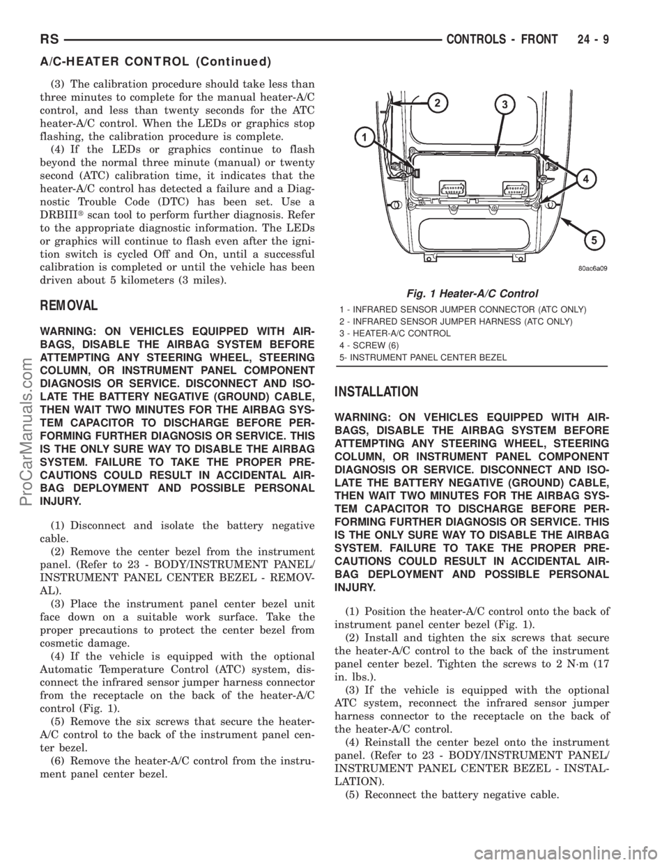
connect the infrared sensor jumper harness connector
from the receptacle on the back of the heater-A/C
control (Fig. 1).
(5) Remove the six screws that secure the heater-
A/C control to the back of the instrument panel cen-
ter bezel.
(6) Remove the heater-A/C control from the instru-
ment panel center bezel.
INSTALLATION
WARNING: ON VEHICLES EQUIPPED WITH AIR-
BAGS, DISABLE THE AIRBAG SYSTEM BEFORE
ATTEMPTING ANY STEERING WHEEL, STEERING
COLUMN, OR INSTRUMENT PANEL COMPONENT
DIAGNOSIS OR SERVICE. DISCONNECT AND ISO-
LATE THE BATTERY NEGATIVE (GROUND) CABLE,
THEN WAIT TWO MINUTES FOR THE AIRBAG SYS-
TEM CAPACITOR TO DISCHARGE BEFORE PER-
FORMING FURTHER DIAGNOSIS OR SERVICE. THIS
IS THE ONLY SURE WAY TO DISABLE THE AIRBAG
SYSTEM. FAILURE TO TAKE THE PROPER PRE-
CAUTIONS COULD RESULT IN ACCIDENTAL AIR-
BAG DEPLOYMENT AND POSSIBLE PERSONAL
INJURY.
(1) Position the heater-A/C control onto the back of
instrument panel center bezel (Fig. 1).
(2) Install and tighten the six screws that secure
the heater-A/C control to the back of the instrument
panel center bezel. Tighten the screws to 2 N´m (17
in. lbs.).
(3) If the vehicle is equipped with the optional
ATC system, reconnect the infrared sensor jumper
harness connector to the receptacle on the back of
the heater-A/C control.
(4) Reinstall the center bezel onto the instrument
panel. (Refer to 23 - BODY/INSTRUMENT PANEL/
INSTRUMENT PANEL CENTER BEZEL - INSTAL-
LATION).
(5) Reconnect the battery negative cable.
Fig. 1 Heater-A/C Control
1 - INFRARED SENSOR JUMPER CONNECTOR (ATC ONLY)
2 - INFRARED SENSOR JUMPER HARNESS (ATC ONLY)
3 - HEATER-A/C CONTROL
4 - SCREW (6)
5- INSTRUMENT PANEL CENTER BEZEL
RSCONTROLS - FRONT24-9
A/C-HEATER CONTROL (Continued)
ProCarManuals.com