2001 DODGE TOWN AND COUNTRY battery location
[x] Cancel search: battery locationPage 44 of 2321
FLUID FILL/CHECK
LOCATIONS
DESCRIPTION
The fluid check/fill points and lubrication locations
are located in each applicable service manual section.
MAINTENANCE SCHEDULES
MAINTENANCE SCHEDULES - DIESEL ENGINE
There are two maintenance schedules that show
proper service for the vehicle.
First is ScheduleªAº. It lists all the scheduled
maintenance to be performed under ªnormalº operat-
ing conditions.
Second is ScheduleªBº. It is a schedule for vehi-
cles that are operated under the conditions listed at
the beginning of the schedule.
Use the schedule that best describes the driving
conditions.
Where time and mileage are listed, follow the
interval that occurs first.
At Each Stop for Fuel
²Check the engine oil level, add as required.
²Check the windshield washer solvent and add if
required.
Once a Month
²Check the tire pressure and look for unusual
wear or damage.
²Inspect the battery and clean and tighten termi-
nals as required.
²Check the fluid levels of coolant reservoir, brake
master cylinder, power steering and transaxle and
add as needed.
²Check all lights and all other electrical items for
correct operation.
²Check the rubber seals on each side of the radi-
ator for proper fit.
At Each Oil Change
²Replace the engine oil filter at each oil change.
²Inspect exhaust system.
²Inspect brake hoses
²Inspect the CV joints and front suspension com-
ponents
²Rotate the tires at each oil change interval
shown on schedule ªAº 20 000 km or every other
interval shown on schedule ªBº 20 000 km.
²Check the coolant level, hoses, and clamps.
²Inspect brake linings, hoses and calipers.
²Inspect engine accessory drive belts.
²Inspect for presence of water in fuel filter/water
separator, drain if necessary.
SCHEDULE ªAº
20 000 km (12 000 miles)
²Change engine oil. (1)
²Replace engine oil filter.
²Inspect air filter element. Replace as necessary.
40 000 km (24 000 Miles)
²Change engine oil. (1)
²Replace engine oil filter.
²Replace air filter element.
²Replace fuel filter/water separator element. (2)
²Check alignment.
60 000 km (37 000 Miles)
²Change engine oil. (1)
²Replace engine oil filter.
²Inspect air filter element. Replace as necessary.
80 000 km (49 000 Miles)
²Change engine oil. (1)
²Replace engine oil filter.
²Replace air filter element.
²Replace fuel filter/water separator element. (2)
²Check alignment.
100 000 km (62 000 Miles)
²Change engine oil. (1)
²Replace engine oil filter.
²Inspect air filter element. Replace as necessary.
120 000 km (75 000 Miles)
²Change engine oil. (1)
²Replace engine oil filter.
²Replace air filter element.
²Replace fuel filter/water separator element. (2)
²Check alignment.
140 000 km (86 000 miles)
²Change engine oil. (1)
²Replace engine oil filter.
²Inspect air filter element. Replace as necessary.
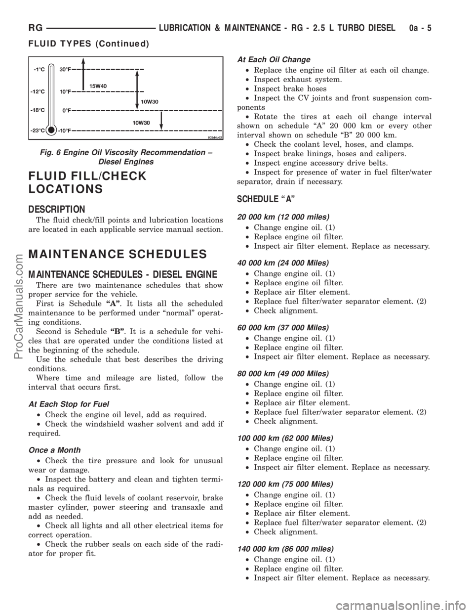
Fig. 6 Engine Oil Viscosity Recommendation ±
Diesel Engines
RGLUBRICATION & MAINTENANCE - RG - 2.5 L TURBO DIESEL0a-5
FLUID TYPES (Continued)
ProCarManuals.com
Page 191 of 2321
STANDARD PROCEDURE - BRAKE FLUID
LEVEL CHECKING
Check master cylinder reservoir fluid level a mini-
mum of twice annually.
Fluid reservoirs are marked with the words FULL
and ADD to indicate proper brake fluid fill level of
the master cylinder.
If necessary, add brake fluid to bring the level to
the bottom of the FULL mark on the side of the mas-
ter cylinder fluid reservoir.
Use only Mopartbrake fluid or equivalent from a
sealed container. Brake fluid must conform to DOT 3
specifications (DOT 4 or DOT 4+ are acceptable).
DO NOTuse brake fluid with a lower boiling
point, as brake failure could result during prolonged
hard braking.
Use only brake fluid that was stored in a tightly-
sealed container.
DO NOTuse petroleum-based fluid because seal
damage will result. Petroleum based fluids would be
items such as engine oil, transmission fluid, power
steering fluid etc.
SPECIFICATIONS
BRAKE FLUID
The brake fluid used in this vehicle must conform
to DOT 3 specifications (DOT 4 and DOT 4+ are
acceptable) and SAE J1703 standards. No other type
of brake fluid is recommended or approved for usage
in the vehicle brake system. Use only MopartBrake
Fluid or equivalent from a tightly sealed container.
CAUTION: Never use reclaimed brake fluid or fluid
from an container which has been left open. An
open container of brake fluid will absorb moisture
from the air and contaminate the fluid.
CAUTION: Never use any type of a petroleum-based
fluid in the brake hydraulic system. Use of such
type fluids will result in seal damage of the vehicle
brake hydraulic system causing a failure of the
vehicle brake system. Petroleum based fluids would
be items such as engine oil, transmission fluid,
power steering fluid, etc.
JUNCTION BLOCK
DESCRIPTION - NON-ABS JUNCTION BLOCK
A junction block is used on vehicles that are not
equipped with antilock brakes (ABS). The junction
block mounts in the same location as the integrated
control unit (ICU) does on vehicles equipped withABS. This allows for use of the same brake tube con-
figuration on all vehicles. The junction block is
located on the driver's side of the front suspension
cradle/crossmember below the master cylinder (Fig.
46).
It has six threaded ports to which the brake tubes
connect. Two are for the primary and secondary
brake tubes coming from the master cylinder. The
remaining four are for the chassis brake tubes going
to each brake assembly.
OPERATION - NON-ABS JUNCTION BLOCK
The junction block distributes the brake fluid com-
ing from the master cylinder primary and secondary
ports to the four chassis brake tubes leading to the
brakes at each wheel. Since the junction block
mounts in the same location as the ABS integrated
control unit (ICU), it allows for the common use of
brake tubes going to the brakes whether the vehicle
is equipped with or without ABS.
NOTE: Although the brake tubes coming from the
master cylinder to the junction block or ABS ICU
may appear to be the same, they are not. They are
unique to each brake system application.
REMOVAL - NON-ABS JUNCTION BLOCK
(1) Using a brake pedal depressor, move and lock
the brake pedal to a position past its first 1 inch of
travel. This will prevent brake fluid from draining
out of the master cylinder when the brake tubes are
removed from the junction block.
(2) Disconnect the battery negative cable.
(3) If the vehicle is equipped with speed control,
perform the following:
(a) Disconnect the battery positive cable.
(b) Remove the battery (Refer to 8 - ELECTRI-
CAL/BATTERY SYSTEM/BATTERY - REMOVAL).
(c) Disconnect the vacuum hose connector at the
tank built into the battery tray.
(d) Remove the screw securing the coolant filler
neck to the battery tray.
(e) Remove the battery tray (Refer to 8 - ELEC-
TRICAL/BATTERY SYSTEM/TRAY - REMOVAL).
(f) Remove the fasteners and move the speed
control servo off to the side, out of the way.
CAUTION: Before removing the brake tubes from
the junction block, the junction block and the brake
tubes must be thoroughly cleaned. This is required
to prevent contamination from entering the brake
hydraulic system.
5 - 32 BRAKES - BASERS
FLUID (Continued)
ProCarManuals.com
Page 192 of 2321
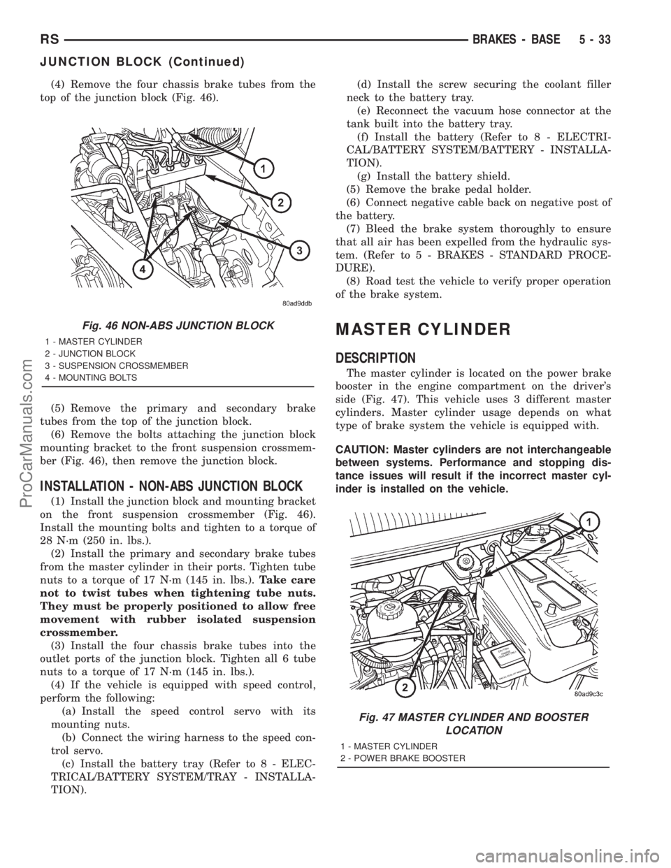
(4) Remove the four chassis brake tubes from the
top of the junction block (Fig. 46).
(5) Remove the primary and secondary brake
tubes from the top of the junction block.
(6) Remove the bolts attaching the junction block
mounting bracket to the front suspension crossmem-
ber (Fig. 46), then remove the junction block.
INSTALLATION - NON-ABS JUNCTION BLOCK
(1) Install the junction block and mounting bracket
on the front suspension crossmember (Fig. 46).
Install the mounting bolts and tighten to a torque of
28 N´m (250 in. lbs.).
(2) Install the primary and secondary brake tubes
from the master cylinder in their ports. Tighten tube
nuts to a torque of 17 N´m (145 in. lbs.).Take care
not to twist tubes when tightening tube nuts.
They must be properly positioned to allow free
movement with rubber isolated suspension
crossmember.
(3) Install the four chassis brake tubes into the
outlet ports of the junction block. Tighten all 6 tube
nuts to a torque of 17 N´m (145 in. lbs.).
(4) If the vehicle is equipped with speed control,
perform the following:
(a) Install the speed control servo with its
mounting nuts.
(b) Connect the wiring harness to the speed con-
trol servo.
(c) Install the battery tray (Refer to 8 - ELEC-
TRICAL/BATTERY SYSTEM/TRAY - INSTALLA-
TION).(d) Install the screw securing the coolant filler
neck to the battery tray.
(e) Reconnect the vacuum hose connector at the
tank built into the battery tray.
(f) Install the battery (Refer to 8 - ELECTRI-
CAL/BATTERY SYSTEM/BATTERY - INSTALLA-
TION).
(g) Install the battery shield.
(5) Remove the brake pedal holder.
(6) Connect negative cable back on negative post of
the battery.
(7) Bleed the brake system thoroughly to ensure
that all air has been expelled from the hydraulic sys-
tem. (Refer to 5 - BRAKES - STANDARD PROCE-
DURE).
(8) Road test the vehicle to verify proper operation
of the brake system.
MASTER CYLINDER
DESCRIPTION
The master cylinder is located on the power brake
booster in the engine compartment on the driver's
side (Fig. 47). This vehicle uses 3 different master
cylinders. Master cylinder usage depends on what
type of brake system the vehicle is equipped with.
CAUTION: Master cylinders are not interchangeable
between systems. Performance and stopping dis-
tance issues will result if the incorrect master cyl-
inder is installed on the vehicle.
Fig. 46 NON-ABS JUNCTION BLOCK
1 - MASTER CYLINDER
2 - JUNCTION BLOCK
3 - SUSPENSION CROSSMEMBER
4 - MOUNTING BOLTS
Fig. 47 MASTER CYLINDER AND BOOSTER
LOCATION
1 - MASTER CYLINDER
2 - POWER BRAKE BOOSTER
RSBRAKES - BASE5-33
JUNCTION BLOCK (Continued)
ProCarManuals.com
Page 211 of 2321
(1) Grasp the exposed section of the front parking
brake cable and pull rearward on it. While holding
the park brake in this position, install a pair of lock-
ing pliers on the front parking brake cable just rear-
ward of the second body outrigger bracket (Fig. 76).
(2) Install the equalizer on the front parking brake
cable.
(3) Install the left rear and intermediate park
brake cable in the correct location on the parking
brake cable equalizer (Fig. 77).
(4) Remove the locking pliers from the front park-
ing brake cable. This will allow the adjuster in the
park brake lever (pedal) mechanism to tension the
park brake cables.
(5) Apply and release the parking brake lever
(pedal) one time. This will seat the parking brake
cables and allow the auto adjuster in the parking
brake lever (pedal) mechanism to correctly tension
the parking brake cables.
LEVER - PARKING BRAKE
REMOVAL
(1) Manually release the automatic self-adjusting
mechanism tension of the parking brake lever (pedal)
assembly. (Refer to 5 - BRAKES/PARKING BRAKE -
STANDARD PROCEDURE).
(2) Disconnect negative (ground) cable from the
battery and isolate cable from battery terminal.
(3) Remove sill scuff plate from left door sill.
(4) Remove the left side kick panel.
(5) Remove the silencer panel under the instru-
ment panel.
(6) Remove the steering column cover from the
lower instrument panel.
(7) Remove the reinforcement from the lower
instrument panel.
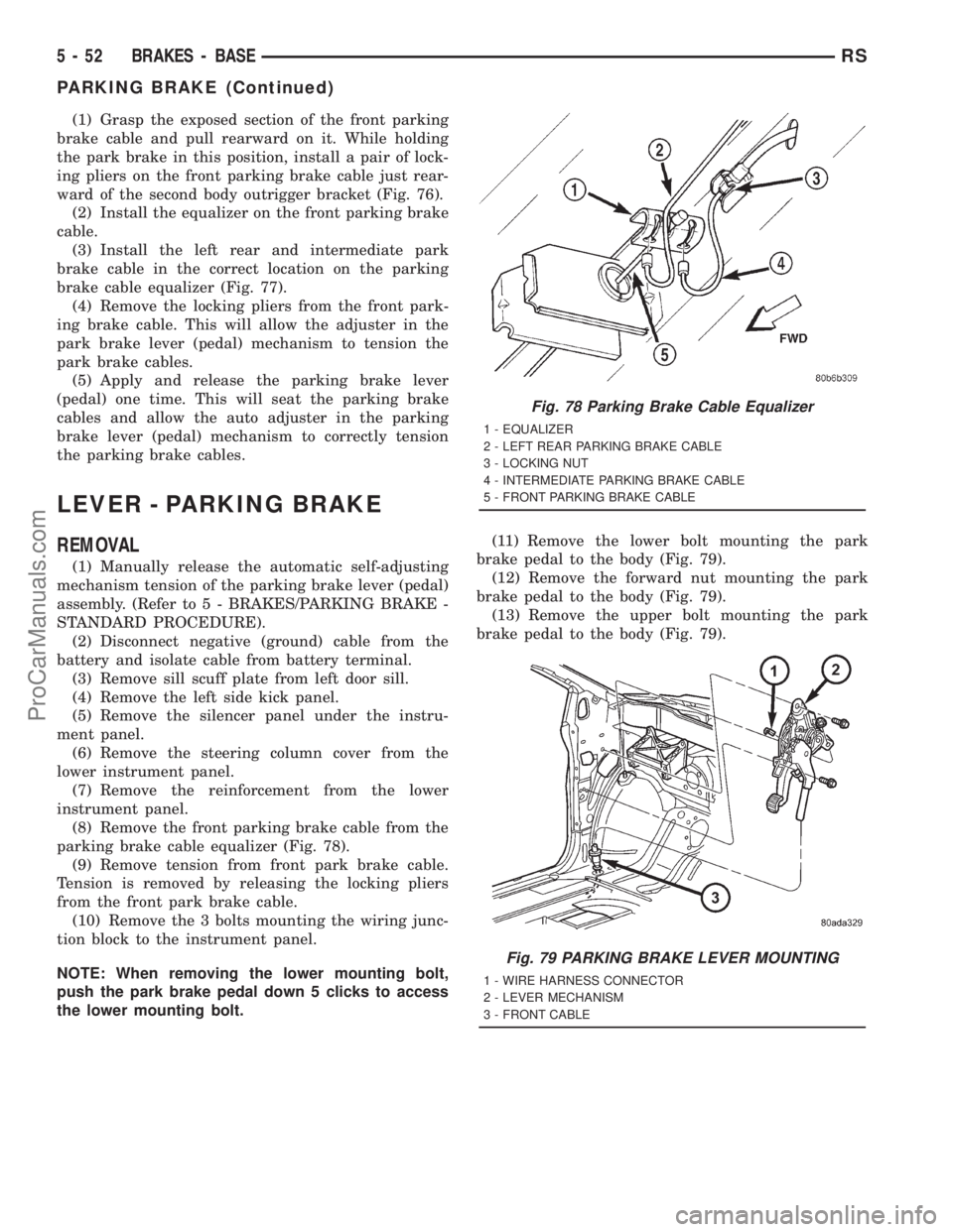
(8) Remove the front parking brake cable from the
parking brake cable equalizer (Fig. 78).
(9) Remove tension from front park brake cable.
Tension is removed by releasing the locking pliers
from the front park brake cable.
(10) Remove the 3 bolts mounting the wiring junc-
tion block to the instrument panel.
NOTE: When removing the lower mounting bolt,
push the park brake pedal down 5 clicks to access
the lower mounting bolt.(11) Remove the lower bolt mounting the park
brake pedal to the body (Fig. 79).
(12) Remove the forward nut mounting the park
brake pedal to the body (Fig. 79).
(13) Remove the upper bolt mounting the park
brake pedal to the body (Fig. 79).
Fig. 78 Parking Brake Cable Equalizer
1 - EQUALIZER
2 - LEFT REAR PARKING BRAKE CABLE
3 - LOCKING NUT
4 - INTERMEDIATE PARKING BRAKE CABLE
5 - FRONT PARKING BRAKE CABLE
Fig. 79 PARKING BRAKE LEVER MOUNTING
1 - WIRE HARNESS CONNECTOR
2 - LEVER MECHANISM
3 - FRONT CABLE
5 - 52 BRAKES - BASERS
PARKING BRAKE (Continued)
ProCarManuals.com
Page 237 of 2321
(2) Inside the vehicle, install the remaining 2
mounting bolts attaching the ICU to the mounting
bracket (Fig. 11). Tighten all 3 mounting bolts to a
torque of 11 N´m (97 in. lbs.).
(3) Install the dash seal and three mounting
screws (Fig. 10).
(4) Install the silencer on top of the dash seal (Fig.
10).
(5) Connect the steering shaft coupling and install
the pinch bolt (Fig. 10). Tighten the pinch bolt to 28
N´m (250 in. lbs.).
(6) Install the silencer panel below the steering
column under the instrument panel.
(7) Remove the steering wheel holder.
CAUTION: Because of the flexible section in the pri-
mary and secondary brake tubes, the brake tubes
must be held in proper orientation when tightened
and torqued. These tubes must not contact each
other or other vehicle components when installed.
Also, after the brake tubes are installed on the HCU,
ensure all spacer clips are reinstalled on the brake
tubes.
(8) Install the primary and secondary brake tubes
into their correct port locations on the HCU valve
block (Fig. 9). Tighten the tube nuts to a torque of 17
N´m (145 in. lbs.).
CAUTION: When installing the chassis brake tubes
on the HCU valve block, they must be located cor-
rectly in the valve block to ensure proper ABS oper-
ation.
NOTE: The chassis brake tube attachment locations
to the HCU, are marked on the bottom of the CAB.
(9) Install the (4) chassis brake tubes into their
correct port locations on the HCU valve block as
shown (Fig. 9). Tighten the tube nuts to a torque of
17 N´m (145 in. lbs.).NOTE: Before installing the 24±way connector in
the CAB be sure the seal is properly installed in the
connector.
(10) Install the 24±way connector on the CAB by,
first, positioning the 24±way connector in the socket
of the CAB and carefully pushing it down as far as
possible. Once connector is fully seated by hand into
the CAB socket, push down on connector lock. This
will pull the connector into the socket of the CAB
and lock it in the installed position.
(11) Install any routing clips on the brake tubes.
(12) Remove the brake pedal holder.
(13) Install the speed control servo with its mount-
ing nuts.
(14) Connect the wiring harness to the speed con-
trol servo.
(15) Install the battery tray (Refer to 8 - ELEC-
TRICAL/BATTERY SYSTEM/TRAY - INSTALLA-
TION).
(16) Install the screw securing the coolant filler
neck to the battery tray.
(17) Reconnect the vacuum hose connector at the
tank built into the battery tray.
(18) Install the battery (Refer to 8 - ELECTRI-
CAL/BATTERY SYSTEM/BATTERY - INSTALLA-
TION).
(19) Install the battery shield.
(20) Remove the brake pedal holder.
(21) Connect negative cable back on negative post
of the battery.
(22) Bleed the Base and ABS brake hydraulic sys-
tems (Refer to 5 - BRAKES - STANDARD PROCE-
DURE).
(23) Road test vehicle to ensure proper operation
of the base and antilock brake systems.
5 - 78 BRAKES - ABSRS
ICU (INTEGRATED CONTROL UNIT) (Continued)
ProCarManuals.com
Page 247 of 2321
BRAKES - ABS
TABLE OF CONTENTS
page page
BRAKES - ABS
DESCRIPTION...........................10
ICU (INTEGRATED CONTROL UNIT) - RHD
REMOVAL..............................10DISASSEMBLY...........................11
ASSEMBLY.............................12
INSTALLATION...........................13
BRAKES - ABS
DESCRIPTION - ANTILOCK BRAKE SYSTEM
Four-wheel disc antilock brakes are standard on all
models. The Mark 20e antilock brake system is used
on all models. Depending on whether the vehicle is a
left-hand drive (LHD) or right-hand drive (RHD)
model, the integrated control unit (ICU) is located in
one of two locations. On LHD models, the ICU is
mounted above the front suspension cradle/cross-
member below the master cylinder. On RHD models,
the ICU is located behind the front suspension cra-
dle/crossmember on the left side of the vehicle.
ICU (INTEGRATED CONTROL
UNIT) - RHD
REMOVAL - RHD
NOTE: Before proceeding, review all WARNINGS
AND CAUTIONS.
(1) Disconnect the negative (ground) cable from
the battery and isolate cable.
(2) Using a brake pedal depressor, move and lock
the brake pedal to a position past the first inch of
pedal travel.This will prevent brake fluid from
draining out of the master cylinder when the
brake tubes are removed from the HCU.
(3) Raise vehicle. See Hoisting in the Lubrication
And Maintenance.
(4) Remove the routing clip attaching the ICU wir-
ing harness to the ICU mounting bracket (Fig. 1).CAUTION: Do not apply a 12 volt power source to
any terminals of the HCU connector when discon-
nected.
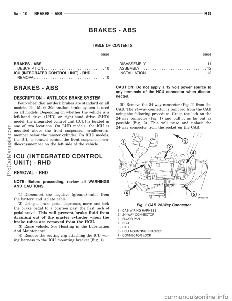
(5) Remove the 24-way connector (Fig. 1) from the
CAB. The 24-way connector is removed from the CAB
using the following procedure. Grasp the lock on the
24-way connector (Fig. 1) and pull it as far out as
possible (Fig. 2). This will raise and unlock the
24-way connector from the socket on the CAB.
Fig. 1 CAB 24-Way Connector
1 - CAB WIRING HARNESS
2 - 24±WAY CONNECTOR
3 - FLOOR PAN
4 - HCU
5 - CAB
6 - HCU MOUNTING BRACKET
7 - CONNECTOR LOCK
5a - 10 BRAKES - ABSRG
ProCarManuals.com
Page 250 of 2321
INSTALLATION - RHD
(1) Install the ICU on the mounting bracket (Fig.
5). Install the 3 bolts (Fig. 5) attaching the ICU to
the mounting bracket. Tighten the 3 mounting bolts
to a torque of 11 N´m (97 in. lbs.).
CAUTION: The ICU mounting bracket to front sus-
pension cradle mounting bolts have a unique corro-
sion protection coating and a special aluminum
washer. For this reason, only the original, or origi-
nal equipment Mopar replacement bolts can be
used to mount the ICU bracket to the front suspen-
sion crossmember.
(2) Install the ICU and its mounting bracket as an
assembly on the front suspension crossmember.
Install the 3 bolts attaching the ICU bracket to the
crossmember (Fig. 4). Tighten the 3 mounting bolts
to a torque of 28 N´m (250 in. lbs.).
CAUTION: Because of the flexible section in the pri-
mary and secondary brake tubes, and the brake
tubes between the HCU and the proportioning
valve, the brake tubes must be held in proper ori-
entation when tightened and torqued. These tubes
must not contact each other or other vehicle com-
ponents when installed. Also, after the brake tubes
are installed on the HCU, ensure all spacer clips are
reinstalled on the brake tubes.
CAUTION: When installing the chassis brake tubes
on the HCU valve block, they must be located cor-
rectly in the valve block to ensure proper ABS oper-
ation. Refer to (Fig. 3) for the correct chassis brake
tube locations.
NOTE: The chassis brake tube attachment locations
to the HCU, are marked on the bottom of the ICU
mounting bracket.
(3) Install the 6 chassis brake tubes into their cor-
rect port locations on the HCU valve block as shown
in (Fig. 3). Tighten the tube nuts to a torque of 17
N´m (145 in. lbs.).
NOTE: Before installing the 24-way connector in the
CAB be sure the seal is properly installed in the
connector.(4) Install the 24-way connector (Fig. 1) on the
CAB using the following procedure. Position the
24-way connector in the socket of the CAB and care-
fully push it down as far as possible. When connector
is fully seated by hand into the CAB socket, push in
the connector lock (Fig. 2). This will pull the connec-
tor into the socket of the CAB and lock it in the
installed position.
NOTE: The CAB wiring harness must be clipped to
the ICU mounting bracket. This will ensure the wir-
ing harness is properly routed and does not contact
the brake tubes or the body of the vehicle.
(5) Clip the cab wiring harness (Fig. 1) to the ICU
mounting bracket.
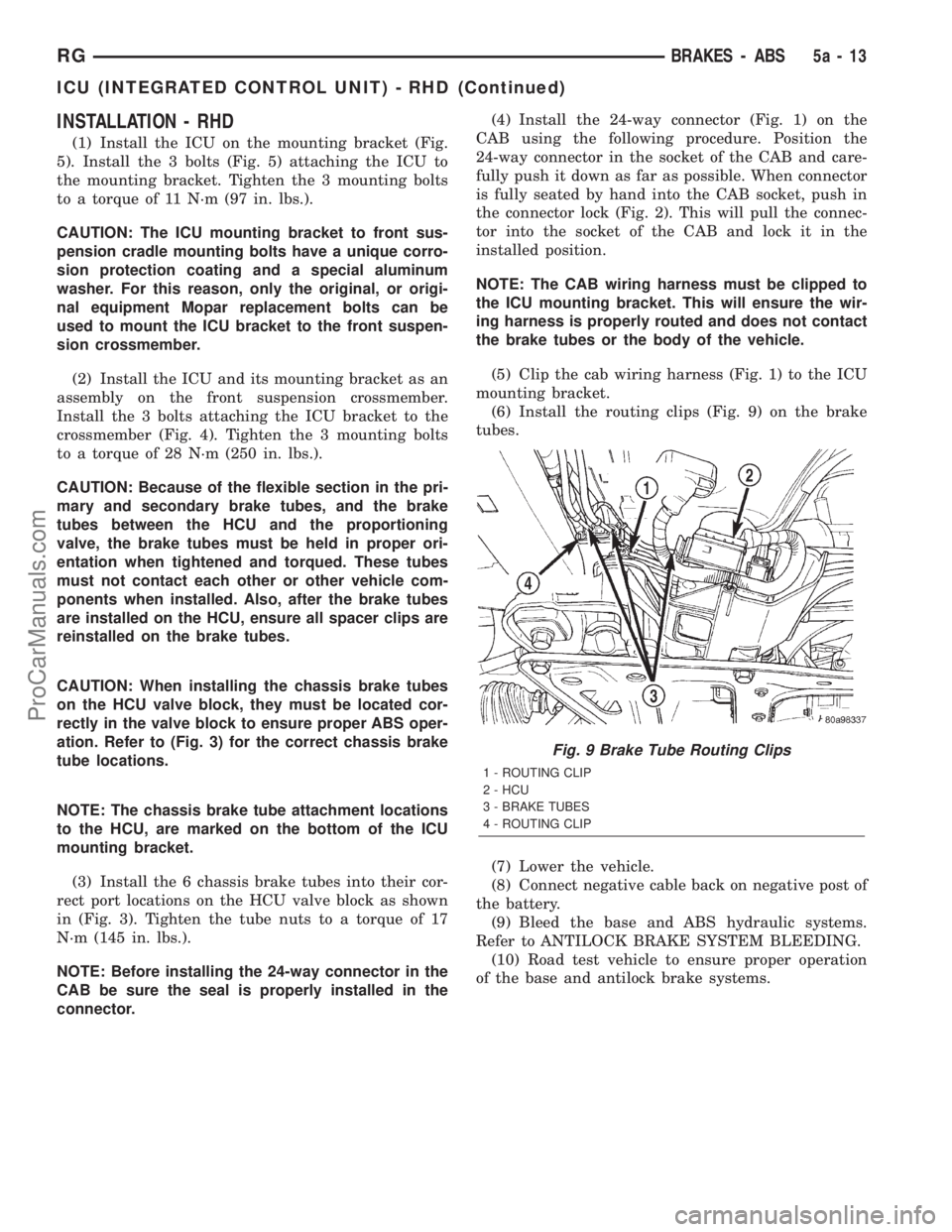
(6) Install the routing clips (Fig. 9) on the brake
tubes.
(7) Lower the vehicle.
(8) Connect negative cable back on negative post of
the battery.
(9) Bleed the base and ABS hydraulic systems.
Refer to ANTILOCK BRAKE SYSTEM BLEEDING.
(10) Road test vehicle to ensure proper operation
of the base and antilock brake systems.
Fig. 9 Brake Tube Routing Clips
1 - ROUTING CLIP
2 - HCU
3 - BRAKE TUBES
4 - ROUTING CLIP
RGBRAKES - ABS5a-13
ICU (INTEGRATED CONTROL UNIT) - RHD (Continued)
ProCarManuals.com
Page 264 of 2321
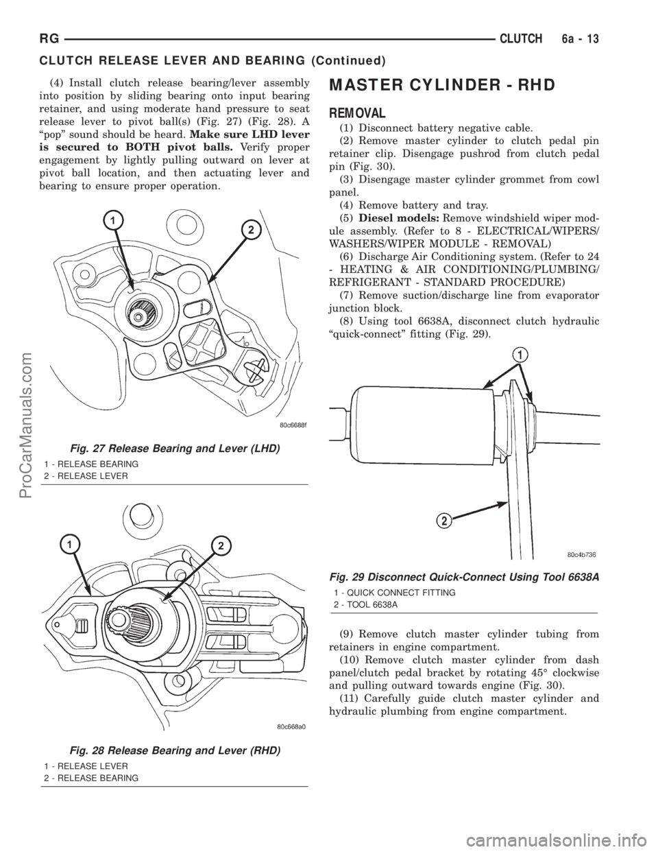
(4) Install clutch release bearing/lever assembly
into position by sliding bearing onto input bearing
retainer, and using moderate hand pressure to seat
release lever to pivot ball(s) (Fig. 27) (Fig. 28). A
ªpopº sound should be heard.Make sure LHD lever
is secured to BOTH pivot balls.Verify proper
engagement by lightly pulling outward on lever at
pivot ball location, and then actuating lever and
bearing to ensure proper operation.MASTER CYLINDER - RHD
REMOVAL
(1) Disconnect battery negative cable.
(2) Remove master cylinder to clutch pedal pin
retainer clip. Disengage pushrod from clutch pedal
pin (Fig. 30).
(3) Disengage master cylinder grommet from cowl
panel.
(4) Remove battery and tray.
(5)Diesel models:Remove windshield wiper mod-
ule assembly. (Refer to 8 - ELECTRICAL/WIPERS/
WASHERS/WIPER MODULE - REMOVAL)
(6) Discharge Air Conditioning system. (Refer to 24
- HEATING & AIR CONDITIONING/PLUMBING/
REFRIGERANT - STANDARD PROCEDURE)
(7) Remove suction/discharge line from evaporator
junction block.
(8) Using tool 6638A, disconnect clutch hydraulic
ªquick-connectº fitting (Fig. 29).
(9) Remove clutch master cylinder tubing from
retainers in engine compartment.
(10) Remove clutch master cylinder from dash
panel/clutch pedal bracket by rotating 45É clockwise
and pulling outward towards engine (Fig. 30).
(11) Carefully guide clutch master cylinder and
hydraulic plumbing from engine compartment.
Fig. 27 Release Bearing and Lever (LHD)
1 - RELEASE BEARING
2 - RELEASE LEVER
Fig. 28 Release Bearing and Lever (RHD)
1 - RELEASE LEVER
2 - RELEASE BEARING
Fig. 29 Disconnect Quick-Connect Using Tool 6638A
1 - QUICK CONNECT FITTING
2 - TOOL 6638A
RGCLUTCH6a-13
CLUTCH RELEASE LEVER AND BEARING (Continued)
ProCarManuals.com