2001 DODGE TOWN AND COUNTRY battery location
[x] Cancel search: battery locationPage 446 of 2321
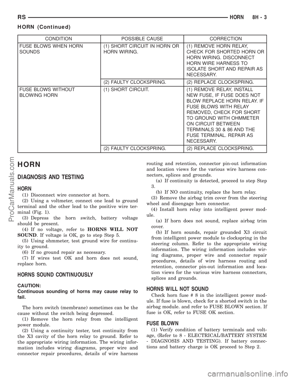
CONDITION POSSIBLE CAUSE CORRECTION
FUSE BLOWS WHEN HORN
SOUNDS(1) SHORT CIRCUIT IN HORN OR
HORN WIRING.(1) REMOVE HORN RELAY,
CHECK FOR SHORTED HORN OR
HORN WIRING. DISCONNECT
HORN WIRE HARNESS TO
ISOLATE SHORT AND REPAIR AS
NECESSARY.
(2) FAULTY CLOCKSPRING. (2) REPLACE CLOCKSPRING.
FUSE BLOWS WITHOUT
BLOWING HORN(1) SHORT CIRCUIT. (1) REMOVE RELAY, INSTALL
NEW FUSE, IF FUSE DOES NOT
BLOW REPLACE HORN RELAY. IF
FUSE BLOWS WITH RELAY
REMOVED, CHECK FOR SHORT
TO GROUND WITH OHMMETER
ON CIRCUIT BETWEEN
TERMINALS 30 & 86 AND THE
FUSE TERMINAL. REPAIR AS
NECESSARY.
(2) FAULTY CLOCKSPRING. (2) REPLACE CLOCKSPRING.
HORN
DIAGNOSIS AND TESTING
HORN
(1) Disconnect wire connector at horn.
(2) Using a voltmeter, connect one lead to ground
terminal and the other lead to the positive wire ter-
minal (Fig. 1).
(3) Depress the horn switch, battery voltage
should be present.
(4) If no voltage, refer toHORNS WILL NOT
SOUND. If voltage is OK, go to step Step 5.
(5) Using ohmmeter, test ground wire for continu-
ity to ground.
(6) If no ground repair as necessary.
(7) If wires test OK and horn does not sound,
replace horn.
HORNS SOUND CONTINUOUSLY
CAUTION:
Continuous sounding of horns may cause relay to
fail.
The horn switch (membrane) sometimes can be the
cause without the switch being depressed.
(1) Remove the horn relay from the intelligent
power module.
(2) Using a continuity tester, test continuity from
the X3 cavity of the horn relay to ground. Refer to
the appropriate wiring information. The wiring infor-
mation includes wiring diagrams, proper wire and
connector repair procedures, details of wire harnessrouting and retention, connector pin-out information
and location views for the various wire harness con-
nectors, splices and grounds.
(a) If continuity is detected, proceed to step Step
3.
(b) If NO continuity, replace the horn relay.
(3) Remove the airbag trim cover from the steering
wheel and disengage horn connector.
(4) Install horn relay into intelligent power mod-
ule.
(a) If horn does not sound, replace airbag trim
cover.
(b) If horn sounds, repair grounded X3 circuit
from intelligent power module to clockspring in the
steering column. Refer to the appropriate wiring
information. The wiring information includes wir-
ing diagrams, proper wire and connector repair
procedures, details of wire harness routing and
retention, connector pin-out information and loca-
tion views for the various wire harness connectors,
splices and grounds.HORNS WILL NOT SOUND
Check horn fuse#8intheintelligent power mod-
ule. If fuse is blown, check for a shorted switch in the
airbag module. and refer to FUSE BLOWN section. If
fuse is OK, refer to FUSE OK section.
FUSE BLOWN
(1) Verify condition of battery terminals and volt-
age, (Refer to 8 - ELECTRICAL/BATTERY SYSTEM
- DIAGNOSIS AND TESTING). If battery connec-
tions and battery charge is OK proceed to Step 2.
RSHORN8H-3
HORN (Continued)
ProCarManuals.com
Page 447 of 2321
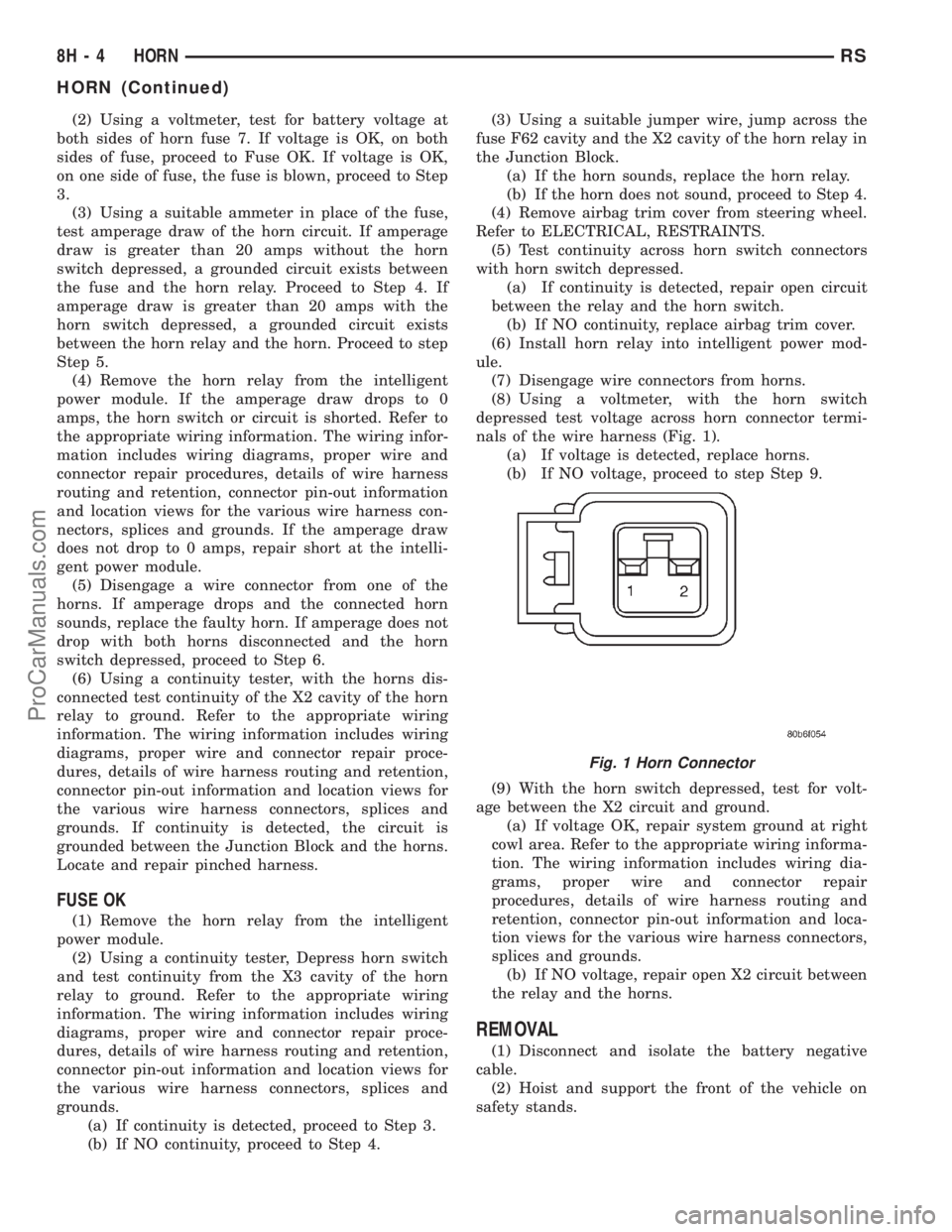
(2) Using a voltmeter, test for battery voltage at
both sides of horn fuse 7. If voltage is OK, on both
sides of fuse, proceed to Fuse OK. If voltage is OK,
on one side of fuse, the fuse is blown, proceed to Step
3.
(3) Using a suitable ammeter in place of the fuse,
test amperage draw of the horn circuit. If amperage
draw is greater than 20 amps without the horn
switch depressed, a grounded circuit exists between
the fuse and the horn relay. Proceed to Step 4. If
amperage draw is greater than 20 amps with the
horn switch depressed, a grounded circuit exists
between the horn relay and the horn. Proceed to step
Step 5.
(4) Remove the horn relay from the intelligent
power module. If the amperage draw drops to 0
amps, the horn switch or circuit is shorted. Refer to
the appropriate wiring information. The wiring infor-
mation includes wiring diagrams, proper wire and
connector repair procedures, details of wire harness
routing and retention, connector pin-out information
and location views for the various wire harness con-
nectors, splices and grounds. If the amperage draw
does not drop to 0 amps, repair short at the intelli-
gent power module.
(5) Disengage a wire connector from one of the
horns. If amperage drops and the connected horn
sounds, replace the faulty horn. If amperage does not
drop with both horns disconnected and the horn
switch depressed, proceed to Step 6.
(6) Using a continuity tester, with the horns dis-
connected test continuity of the X2 cavity of the horn
relay to ground. Refer to the appropriate wiring
information. The wiring information includes wiring
diagrams, proper wire and connector repair proce-
dures, details of wire harness routing and retention,
connector pin-out information and location views for
the various wire harness connectors, splices and
grounds. If continuity is detected, the circuit is
grounded between the Junction Block and the horns.
Locate and repair pinched harness.
FUSE OK
(1) Remove the horn relay from the intelligent
power module.
(2) Using a continuity tester, Depress horn switch
and test continuity from the X3 cavity of the horn
relay to ground. Refer to the appropriate wiring
information. The wiring information includes wiring
diagrams, proper wire and connector repair proce-
dures, details of wire harness routing and retention,
connector pin-out information and location views for
the various wire harness connectors, splices and
grounds.
(a) If continuity is detected, proceed to Step 3.
(b) If NO continuity, proceed to Step 4.(3) Using a suitable jumper wire, jump across the
fuse F62 cavity and the X2 cavity of the horn relay in
the Junction Block.
(a) If the horn sounds, replace the horn relay.
(b) If the horn does not sound, proceed to Step 4.
(4) Remove airbag trim cover from steering wheel.
Refer to ELECTRICAL, RESTRAINTS.
(5) Test continuity across horn switch connectors
with horn switch depressed.
(a) If continuity is detected, repair open circuit
between the relay and the horn switch.
(b) If NO continuity, replace airbag trim cover.
(6) Install horn relay into intelligent power mod-
ule.
(7) Disengage wire connectors from horns.
(8) Using a voltmeter, with the horn switch
depressed test voltage across horn connector termi-
nals of the wire harness (Fig. 1).
(a) If voltage is detected, replace horns.
(b) If NO voltage, proceed to step Step 9.
(9) With the horn switch depressed, test for volt-
age between the X2 circuit and ground.
(a) If voltage OK, repair system ground at right
cowl area. Refer to the appropriate wiring informa-
tion. The wiring information includes wiring dia-
grams, proper wire and connector repair
procedures, details of wire harness routing and
retention, connector pin-out information and loca-
tion views for the various wire harness connectors,
splices and grounds.
(b) If NO voltage, repair open X2 circuit between
the relay and the horns.
REMOVAL
(1) Disconnect and isolate the battery negative
cable.
(2) Hoist and support the front of the vehicle on
safety stands.
Fig. 1 Horn Connector
8H - 4 HORNRS
HORN (Continued)
ProCarManuals.com
Page 448 of 2321
(3) From behind the front fascia and forward of
the left front wheel, disconnect the wire connectors
from horn.
(4) Remove the mounting bracket attaching nut
from the bottom of radiator closure panel. Do not
remove the horn from mounting bracket.
(5) Separate the horn(s) from vehicle.
INSTALLATION
(1) Install the horns to the vehicle.
(2) Install the mounting bracket nut.
(3) Reconnect the wire connectors to the horns.
(4) Lower the vehicle.
(5) Reconnect the battery negative cable.
HORN RELAY
DIAGNOSIS AND TESTING
(1) Remove horn relay.
(2) Using ohmmeter, test between relay connector
terminals 85 to 86 for 70 to 75 ohms resistance. If
resistance not OK, replace relay.
(3) Test for continuity between ground and termi-
nal 85 of horn relay.
(a) When the horn switch is not depressed, no
continuity should be present.
(b) Continuity to ground when horn switch is
depressed.
(c) If continuity is not correct repair horn
switch or wiring as necessary, refer to the appro-
priate wiring information. The wiring information
includes wiring diagrams, proper wire and connec-
tor repair procedures, details of wire harness rout-
ing and retention, connector pin-out information
and location views for the various wire harness
connectors, splices and grounds.
(4) Using voltmeter, test voltage at:
(a) Terminals 30 and 86 of the horn relay to
body ground.(b) If NO voltage check fuse 8 of the intelligent
power module.
(c) If incorrect voltage, repair as necessary. Refer
to the appropriate wiring information. The wiring
information includes wiring diagrams, proper wire
and connector repair procedures, details of wire
harness routing and retention, connector pin-out
information and location views for the various wire
harness connectors, splices and grounds.
(5) Insert a jumper wire between terminal 30 and
87 of the intelligent power module.
(a) If horn sounds replace relay.
(b) If the horn does not sound, install horn relay
and refer to Horn Test.
REMOVAL
(1) Disconnect and isolate the battery negative
cable.
(2) Remove cover from the intelligent power mod-
ule.
(3) Remove relay from intelligent power module.
INSTALLATION
(1) Push relay into intelligent power module.
(2) Install cover.
(3) Reconnect battery negative cable.
HORN SWITCH
DESCRIPTION
The horn switch is molded into the airbag trim
cover. The horn switch can not be serviced separately.
For service procedures, refer to ELECTRICAL /
RESTRAINTS.
RSHORN8H-5
HORN (Continued)
ProCarManuals.com
Page 452 of 2321

AUTO SHUT DOWN RELAY
DESCRIPTION
The relay is located in the Power Distribution Cen-
ter (PDC). For the location of the relay within the
PDC, refer to the PDC cover for location. Check elec-
trical terminals for corrosion and repair as necessary
OPERATION
The ASD sense circuit informs the PCM when the
ASD relay energizes. A 12 volt signal at this input
indicates to the PCM that the ASD has been acti-
vated. This input is used only to sense that the ASD
relay is energized.
When energized, the ASD relay supplies battery
voltage to the fuel injectors, ignition coils and the
heating element in each oxygen sensor. If the PCM
does not receive 12 volts from this input after
grounding the ASD relay, it sets a Diagnostic Trouble
Code (DTC).
When energized, the ASD relay provides power to
operate the injectors, ignition coil, generator field, O2
sensor heaters (both upstream and downstream), and
also provides a sense circuit to the PCM for diagnos-
tic purposes. The PCM energizes the ASD any time
there is a Crankshaft Position sensor signal that
exceeds a predetermined value. The ASD relay can
also be energized after the engine has been turned
off to perform an O2 sensor heater test, if vehicle is
equipped with OBD II diagnostics.
As mentioned earlier, the PCM energizes the ASD
relay during an O2 sensor heater test. This test is
performed only after the engine has been shut off.
The PCM still operates internally to perform several
checks, including monitoring the O2 sensor heaters.
CAMSHAFT POSITION
SENSOR
DESCRIPTION
The camshaft position sensorfor the 3.3/3.8L is
mounted in the front of the timing case cover (Fig. 7)
and the camshaft position sensor for the 2.4L is
mounted on the end of the cylinder head (Fig. 4).
OPERATION
The camshaft position sensor provides cylinder
identification to the Powertrain Control Module
(PCM) (Fig. 2). The sensor generates pulses as
groups of notches on the camshaft sprocket pass
underneath it (Fig. 3). The PCM keeps track of
crankshaft rotation and identifies each cylinder by
the pulses generated by the notches on the camshaftsprocket. Four crankshaft pulses follow each group of
camshaft pulses.
When the PCM receives 2 cam pulses followed by
the long flat spot on the camshaft sprocket, it knows
that the crankshaft timing marks for cylinder 1 are
next (on driveplate). When the PCM receives one
camshaft pulse after the long flat spot on the
sprocket, cylinder number 2 crankshaft timing marks
are next. After 3 camshaft pulses, the PCM knows
cylinder 4 crankshaft timing marks follow. One cam-
shaft pulse after the 3 pulses indicates cylinder 5.
The 2 camshaft pulses after cylinder 5 signals cylin-
der 6 (Fig. 3). The PCM can synchronize on cylinders
1or4.
When metal aligns with the sensor, voltage goes
low (less than 0.3 volts). When a notch aligns with
the sensor, voltage switches high (5.0 volts). As a
group of notches pass under the sensor, the voltage
switches from low (metal) to high (notch) then back
to low. The number of notches determine the amount
of pulses. If available, an oscilloscope can display the
square wave patterns of each timing event.
Top Dead Center (TDC) does not occur when
notches on the camshaft sprocket pass below the cyl-
inder. TDC occurs after the camshaft pulse (or
pulses) and after the 4 crankshaft pulses associated
with the particular cylinder. The arrows and cylinder
call outs on Figure 4 represent which cylinder the
flat spot and notches identify, they do not indicate
TDC position.
REMOVAL - 2.4L
The camshaft position sensor is mounted to the
rear of the cylinder head.
(1) Remove the negative battery cable.
Fig. 2 Camshaft Position Sensor
1 - ELECTRICAL CONNECTOR
2 - O-RING
3 - PAPER SPACER
RSIGNITION CONTROL8I-3
ProCarManuals.com
Page 476 of 2321
DAYTIME RUNNING LAMPS
Power is reduced using pulse-width modulation to
the high beams, where by the power is switched on
and off rapidly instead of remaining on continuously.
The duration and interval of the power pulses is pro-
grammed into the Front Control Module (FCM).
HEADLAMP SYSTEM
The headlamp system will default to headlamps
ON position when ignition switch is ON and when an
open or short circuit failure occurs on the headlamp
switch input. The system will return to normal oper-
ation when the open or short is repaired. A fault will
be reported by the BCM when a failure occurs on the
dimmer or headlamp switch input.
If the exterior lamps are ON and the headlamp
switch is in any position other than OFF or AUTO
and with the ignition switch OFF (LOCK) after 3
minutes the BCM sends a message via J1850 to the
FCM informing the FCM to turn off the headlamps,
park lamps and fog lamps. This feature prevents the
vehicle battery from being discharged when the vehi-
cle lights have been left ON.
HEADLAMP TIME DELAY SYSTEM
The headlamp time delay system is activated by
turning the headlamps ON (high or low beam) while
the engine is running, turning the ignition switch
OFF, and then turning the headlamp switch OFF
within 45 seconds. The system will not activate if
more than 45 seconds elapse between ignition switch
OFF and headlamp switch OFF. The BCM will allow
the headlamps to remain ON for 90 seconds (config-
urable) before they automatically turn off (If the key
is in the ignition during the headlamp time delay
mode, then both the headlamps and park lamps
(including panel dimming) will be ON). Refer to the
Owner's Manual for more information.
If the headlamp switch is in the Auto Headlamp
Position, the headlamps are ON due to the night sig-
nal from the CMTC and the ignition switch is in any
position other than run/start, the BCM shall enter a
90 second (configurable) Auto Headlamps time delay
mode. If the key is in the ignition during the head-
lamp time delay mode, then both the headlamps and
park lamps (including panel dimming) will be ON. If
the key is not in the ignition, then only the head-
lamps will be ON. The BCM will allow the head-
lamps to remain ON for 90 seconds before they
automatically turn OFF. Refer to the Owner's Man-
ual for more information.
LAMP OUTAGE
If one or more of the following lamps (Low and/or
High beams) are out, then a ªlamps outº indicator
located in the cluster will illuminate.
OPTICAL HORN/HIGH BEAMS
When the multifunction switch is pulled to the first
detent (optical horn) signal, the headlamps are ON,
key-in the ignition the BCM shall send a message via
J1850 to the FCM to turn on the headlamps drivers
to illuminate all four filaments (Low and High
beams). When the multifunction switch is pulled to
the second detent (high beam) signal and the head-
lamps are ON, the BCM shall send a message via
J1850 to the FCM to turn on the headlamps drivers.
The High Beams are illuminated and the Low Beams
and Fog Lamps (if ON) are extinguished. If the head-
lamps were in the high beam configuration when
power was removed from the headlamps, the head-
lamps will be configured as low beam the next time
they are activated.
DIAGNOSIS AND TESTING
WARNING: EYE PROTECTION SHOULD BE USED
WHEN SERVICING GLASS COMPONENTS. PER-
SONAL INJURY CAN RESULT.
CAUTION: Do not touch the glass of halogen bulbs
with fingers or other possibly oily surface, reduced
bulb life will result. Do not use bulbs other than
those indicated in the Bulb Application table. Dam-
age to lamp and/or Daytime Running Lamp Module
can result. Do not use fuses, circuit breakers or
relays having greater amperage value than indi-
cated on the fuse panel or in the Owners Manual.
When a vehicle experiences problems with the
headlamp system, verify the condition of the battery
connections, fuses, charging system, headlamp bulbs,
wire connectors, relay, high beam switch, dimmer
switch, and headlamp switch. Refer to the appropri-
ate wiring information. The wiring information
includes wiring diagrams, proper wire and connector
repair procedures, details of wire harness routing
and retention, connector pin-out information and
location views for the various wire harness connec-
tors, splices and grounds.
Each vehicle is equipped with various lamp assem-
blies. A good ground is necessary for proper lighting
operation. Grounding is provided by the lamp socket
when it comes in contact with the metal body, or
through a separate ground wire.
When changing lamp bulbs check the socket for
corrosion. If corrosion is present, clean it with a wire
brush.
When it is necessary to remove components to ser-
vice another, it should not be necessary to apply
excessive force or bend a component to remove it.
Before damaging a trim component, verify hidden
fasteners or captured edges are not holding the com-
ponent in place.
RSLAMPS/LIGHTING - EXTERIOR8L-3
LAMPS/LIGHTING - EXTERIOR (Continued)
ProCarManuals.com
Page 477 of 2321
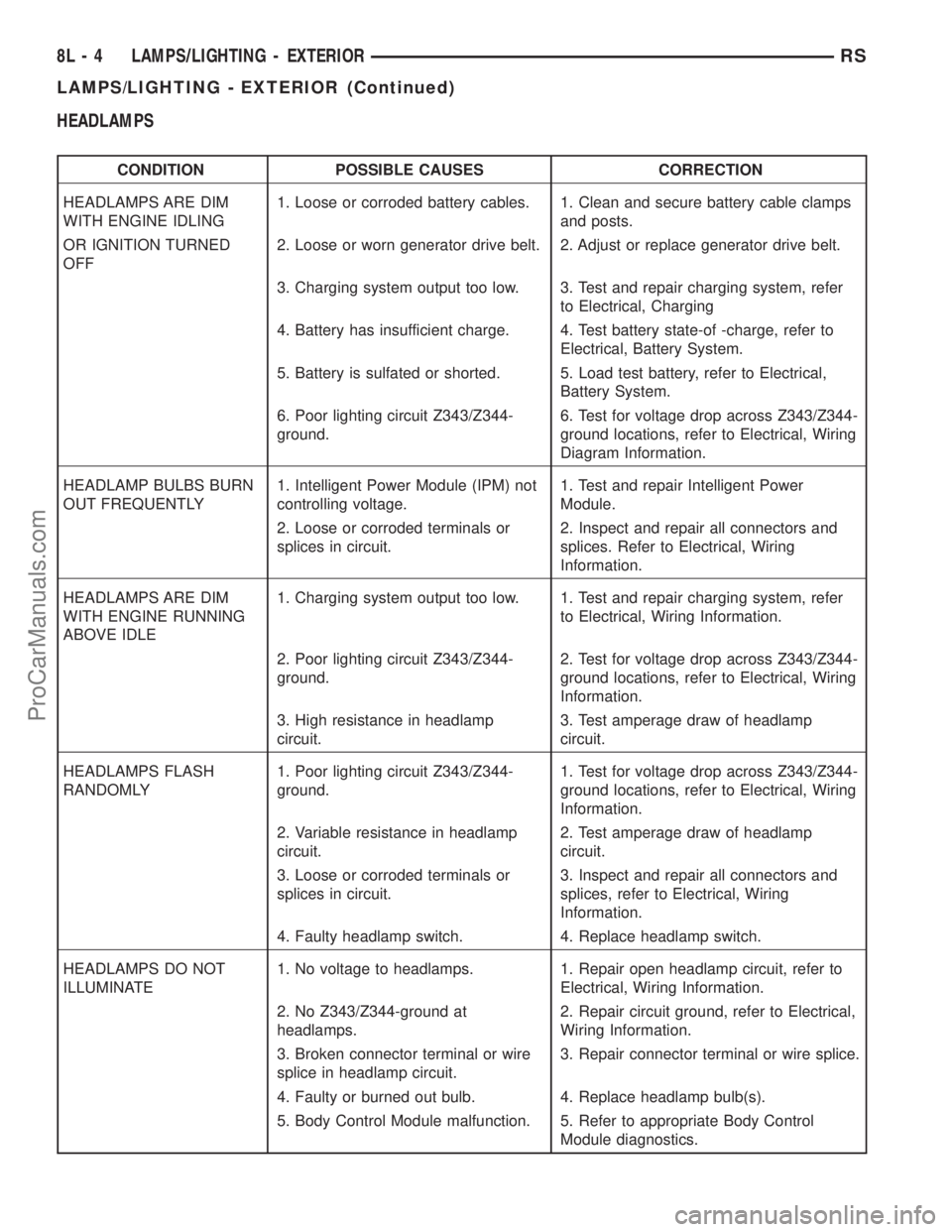
HEADLAMPS
CONDITION POSSIBLE CAUSES CORRECTION
HEADLAMPS ARE DIM
WITH ENGINE IDLING1. Loose or corroded battery cables. 1. Clean and secure battery cable clamps
and posts.
OR IGNITION TURNED
OFF2. Loose or worn generator drive belt. 2. Adjust or replace generator drive belt.
3. Charging system output too low. 3. Test and repair charging system, refer
to Electrical, Charging
4. Battery has insufficient charge. 4. Test battery state-of -charge, refer to
Electrical, Battery System.
5. Battery is sulfated or shorted. 5. Load test battery, refer to Electrical,
Battery System.
6. Poor lighting circuit Z343/Z344-
ground.6. Test for voltage drop across Z343/Z344-
ground locations, refer to Electrical, Wiring
Diagram Information.
HEADLAMP BULBS BURN
OUT FREQUENTLY1. Intelligent Power Module (IPM) not
controlling voltage.1. Test and repair Intelligent Power
Module.
2. Loose or corroded terminals or
splices in circuit.2. Inspect and repair all connectors and
splices. Refer to Electrical, Wiring
Information.
HEADLAMPS ARE DIM
WITH ENGINE RUNNING
ABOVE IDLE1. Charging system output too low. 1. Test and repair charging system, refer
to Electrical, Wiring Information.
2. Poor lighting circuit Z343/Z344-
ground.2. Test for voltage drop across Z343/Z344-
ground locations, refer to Electrical, Wiring
Information.
3. High resistance in headlamp
circuit.3. Test amperage draw of headlamp
circuit.
HEADLAMPS FLASH
RANDOMLY1. Poor lighting circuit Z343/Z344-
ground.1. Test for voltage drop across Z343/Z344-
ground locations, refer to Electrical, Wiring
Information.
2. Variable resistance in headlamp
circuit.2. Test amperage draw of headlamp
circuit.
3. Loose or corroded terminals or
splices in circuit.3. Inspect and repair all connectors and
splices, refer to Electrical, Wiring
Information.
4. Faulty headlamp switch. 4. Replace headlamp switch.
HEADLAMPS DO NOT
ILLUMINATE1. No voltage to headlamps. 1. Repair open headlamp circuit, refer to
Electrical, Wiring Information.
2. No Z343/Z344-ground at
headlamps.2. Repair circuit ground, refer to Electrical,
Wiring Information.
3. Broken connector terminal or wire
splice in headlamp circuit.3. Repair connector terminal or wire splice.
4. Faulty or burned out bulb. 4. Replace headlamp bulb(s).
5. Body Control Module malfunction. 5. Refer to appropriate Body Control
Module diagnostics.
8L - 4 LAMPS/LIGHTING - EXTERIORRS
LAMPS/LIGHTING - EXTERIOR (Continued)
ProCarManuals.com
Page 478 of 2321
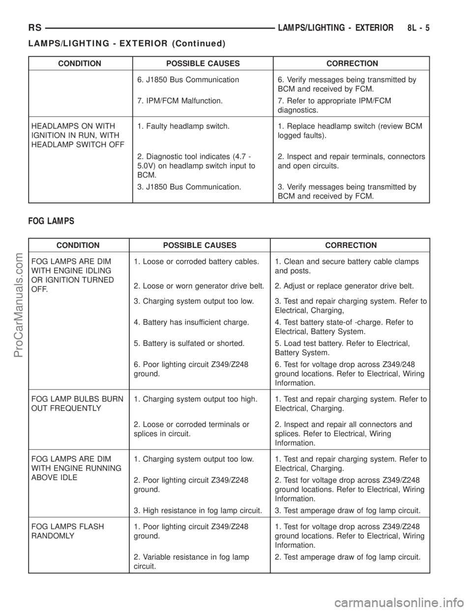
CONDITION POSSIBLE CAUSES CORRECTION
6. J1850 Bus Communication 6. Verify messages being transmitted by
BCM and received by FCM.
7. IPM/FCM Malfunction. 7. Refer to appropriate IPM/FCM
diagnostics.
HEADLAMPS ON WITH
IGNITION IN RUN, WITH
HEADLAMP SWITCH OFF1. Faulty headlamp switch. 1. Replace headlamp switch (review BCM
logged faults).
2. Diagnostic tool indicates (4.7 -
5.0V) on headlamp switch input to
BCM.2. Inspect and repair terminals, connectors
and open circuits.
3. J1850 Bus Communication. 3. Verify messages being transmitted by
BCM and received by FCM.
FOG LAMPS
CONDITION POSSIBLE CAUSES CORRECTION
FOG LAMPS ARE DIM
WITH ENGINE IDLING
OR IGNITION TURNED
OFF.1. Loose or corroded battery cables. 1. Clean and secure battery cable clamps
and posts.
2. Loose or worn generator drive belt. 2. Adjust or replace generator drive belt.
3. Charging system output too low. 3. Test and repair charging system. Refer to
Electrical, Charging,
4. Battery has insufficient charge. 4. Test battery state-of -charge. Refer to
Electrical, Battery System.
5. Battery is sulfated or shorted. 5. Load test battery. Refer to Electrical,
Battery System.
6. Poor lighting circuit Z349/Z248
ground.6. Test for voltage drop across Z349/248
ground locations. Refer to Electrical, Wiring
Information.
FOG LAMP BULBS BURN
OUT FREQUENTLY1. Charging system output too high. 1. Test and repair charging system. Refer to
Electrical, Charging.
2. Loose or corroded terminals or
splices in circuit.2. Inspect and repair all connectors and
splices. Refer to Electrical, Wiring
Information.
FOG LAMPS ARE DIM
WITH ENGINE RUNNING
ABOVE IDLE1. Charging system output too low. 1. Test and repair charging system. Refer to
Electrical, Charging.
2. Poor lighting circuit Z349/Z248
ground.2. Test for voltage drop across Z349/Z248
ground locations. Refer to Electrical, Wiring
Information.
3. High resistance in fog lamp circuit. 3. Test amperage draw of fog lamp circuit.
FOG LAMPS FLASH
RANDOMLY1. Poor lighting circuit Z349/Z248
ground.1. Test for voltage drop across Z349/Z248
ground locations. Refer to Electrical, Wiring
Information.
2. Variable resistance in fog lamp
circuit.2. Test amperage draw of fog lamp circuit.
RSLAMPS/LIGHTING - EXTERIOR8L-5
LAMPS/LIGHTING - EXTERIOR (Continued)
ProCarManuals.com
Page 487 of 2321
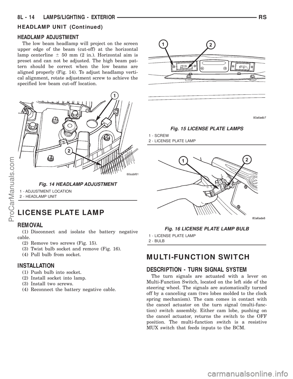
HEADLAMP ADJUSTMENT
The low beam headlamp will project on the screen
upper edge of the beam (cut-off) at the horizontal
lamp centerline650 mm (2 in.). Horizontal aim is
preset and can not be adjusted. The high beam pat-
tern should be correct when the low beams are
aligned properly (Fig. 14). To adjust headlamp verti-
cal alignment, rotate adjustment screw to achieve the
specified low beam cut-off location.
LICENSE PLATE LAMP
REMOVAL
(1) Disconnect and isolate the battery negative
cable.
(2) Remove two screws (Fig. 15).
(3) Twist bulb socket and remove (Fig. 16).
(4) Pull bulb from socket.
INSTALLATION
(1) Push bulb into socket.
(2) Install socket into lamp.
(3) Install two screws.
(4) Reconnect the battery negative cable.
MULTI-FUNCTION SWITCH
DESCRIPTION - TURN SIGNAL SYSTEM
The turn signals are actuated with a lever on
Multi-Function Switch, located on the left side of the
steering wheel. The signals are automatically turned
off by a canceling cam (two lobes molded to the clock
spring mechanism). The cam comes in contact with
the cancel actuator on the turn signal (multi-func-
tion) switch assembly. Either cam lobe, pushing on
the cancel actuator, returns the switch to the OFF
position. The multi-function switch is a resistive
MUX switch that feeds inputs to the BCM.
Fig. 14 HEADLAMP ADJUSTMENT
1 - ADJUSTMENT LOCATION
2 - HEADLAMP UNIT
Fig. 15 LICENSE PLATE LAMPS
1 - SCREW
2 - LICENSE PLATE LAMP
Fig. 16 LICENSE PLATE LAMP BULB
1 - LICENSE PLATE LAMP
2 - BULB
8L - 14 LAMPS/LIGHTING - EXTERIORRS
HEADLAMP UNIT (Continued)
ProCarManuals.com