2001 DODGE TOWN AND COUNTRY instrument panel
[x] Cancel search: instrument panelPage 2 of 2321
INTRODUCTION
TABLE OF CONTENTS
page page
VEHICLE SAFETY CERTIFICATION LABEL
DESCRIPTION............................1
VEHICLE IDENTIFICATION NUMBER
DESCRIPTION............................1
VECI LABEL
DESCRIPTION............................3
BODY CODE PLATE
DESCRIPTION............................3
INTERNATIONAL SYMBOLS
DESCRIPTION............................4FASTENER IDENTIFICATION
DESCRIPTION............................5
FASTENER USAGE
DESCRIPTION............................5
METRIC SYSTEM
DESCRIPTION............................8
TORQUE REFERENCES
DESCRIPTION...........................10
VEHICLE SAFETY
CERTIFICATION LABEL
DESCRIPTION
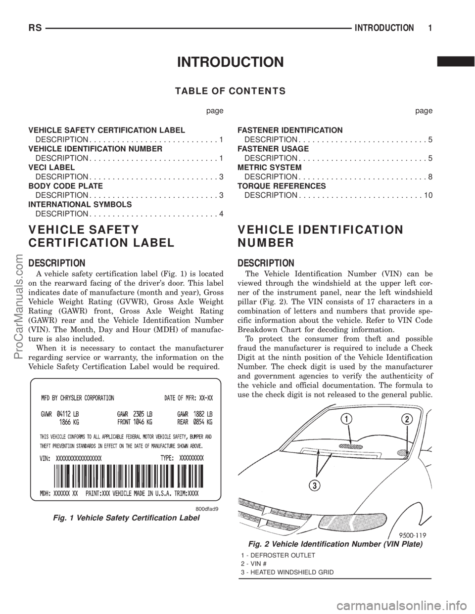
A vehicle safety certification label (Fig. 1) is located
on the rearward facing of the driver's door. This label
indicates date of manufacture (month and year), Gross
Vehicle Weight Rating (GVWR), Gross Axle Weight
Rating (GAWR) front, Gross Axle Weight Rating
(GAWR) rear and the Vehicle Identification Number
(VIN). The Month, Day and Hour (MDH) of manufac-
ture is also included.
When it is necessary to contact the manufacturer
regarding service or warranty, the information on the
Vehicle Safety Certification Label would be required.
VEHICLE IDENTIFICATION
NUMBER
DESCRIPTION
The Vehicle Identification Number (VIN) can be
viewed through the windshield at the upper left cor-
ner of the instrument panel, near the left windshield
pillar (Fig. 2). The VIN consists of 17 characters in a
combination of letters and numbers that provide spe-
cific information about the vehicle. Refer to VIN Code
Breakdown Chart for decoding information.
To protect the consumer from theft and possible
fraud the manufacturer is required to include a Check
Digit at the ninth position of the Vehicle Identification
Number. The check digit is used by the manufacturer
and government agencies to verify the authenticity of
the vehicle and official documentation. The formula to
use the check digit is not released to the general public.
Fig. 1 Vehicle Safety Certification Label
Fig. 2 Vehicle Identification Number (VIN Plate)
1 - DEFROSTER OUTLET
2 - VIN #
3 - HEATED WINDSHIELD GRID
RSINTRODUCTION1
ProCarManuals.com
Page 5 of 2321
DIGIT 13 AND 14
Open Space
DIGITS 15 THROUGH 18
Interior Trim Code
DIGIT 19
Open Space
DIGITS 20, 21, AND 22
Engine Code
²EDZ = 2.4 L 4 cyl. DOHC Gasoline
²EFA = 3.0 L 6 cyl. Gasoline
²EGA = 3.3 L 6 cyl. Gasoline
²EGH = 3.8 L 6 cyl. Gasoline
²EGM = 3.3 L 6 cyl. Ethanol Flexible Fuel
DIGIT 23
Open Space
BODY CODE PLATE LINE 1
DIGITS 1, 2, AND 3
Transaxle Codes
²DGB = 41TH 4-speed Automatic Transaxle
²DGL = 41TE 4-speed Electronic Automatic Tran-
saxle
²DGM = 31TH 3-speed Automatic Transaxle
DIGIT 4
Open SpaceDIGIT 5
Market Code
²C = Canada
²B = International
²M = Mexico
²U = United States
DIGIT 6
Open Space
DIGITS 7 THROUGH 23
Vehicle Identification Number
²Refer to Vehicle Identification Number (VIN)
paragraph for proper breakdown of VIN code.
IF TWO BODY CODE PLATES ARE REQUIRED
The last code shown on either plate will be fol-
lowed by END. When two plates are required, the
last code space on the first plate will indicate (CTD)
When a second plate is required, the first four
spaces of each line will not be used due to overlap of
the plates.
INTERNATIONAL SYMBOLS
DESCRIPTION
The graphic symbols illustrated in the following
International Control and Display Symbols Chart are
used to identify various instrument controls. The
symbols correspond to the controls and displays that
are located on the instrument panel.
4 INTRODUCTIONRS
BODY CODE PLATE (Continued)
ProCarManuals.com
Page 16 of 2321
FASTENER USAGE
DESCRIPTION
WARNING: USE OF AN INCORRECT FASTENER
MAY RESULT IN COMPONENT DAMAGE OR PER-
SONAL INJURY.
Figure art, specifications and torque references in
this Service Manual are identified in metric and SAE
format.
During any maintenance or repair procedures, it is
important to salvage all fasteners (nuts, bolts, etc.)
for reassembly. If the fastener is not salvageable, a
fastener of equivalent specification must be used.
THREADED HOLE REPAIR
DESCRIPTION
Most stripped threaded holes can be repaired using
a Helicoilt. Follow the vehicle or Helicoiltrecommen-
dations for application and repair procedures.
INTERNATIONAL VEHICLE
CONTROL & DISPLAY
SYMBOLS
DESCRIPTION
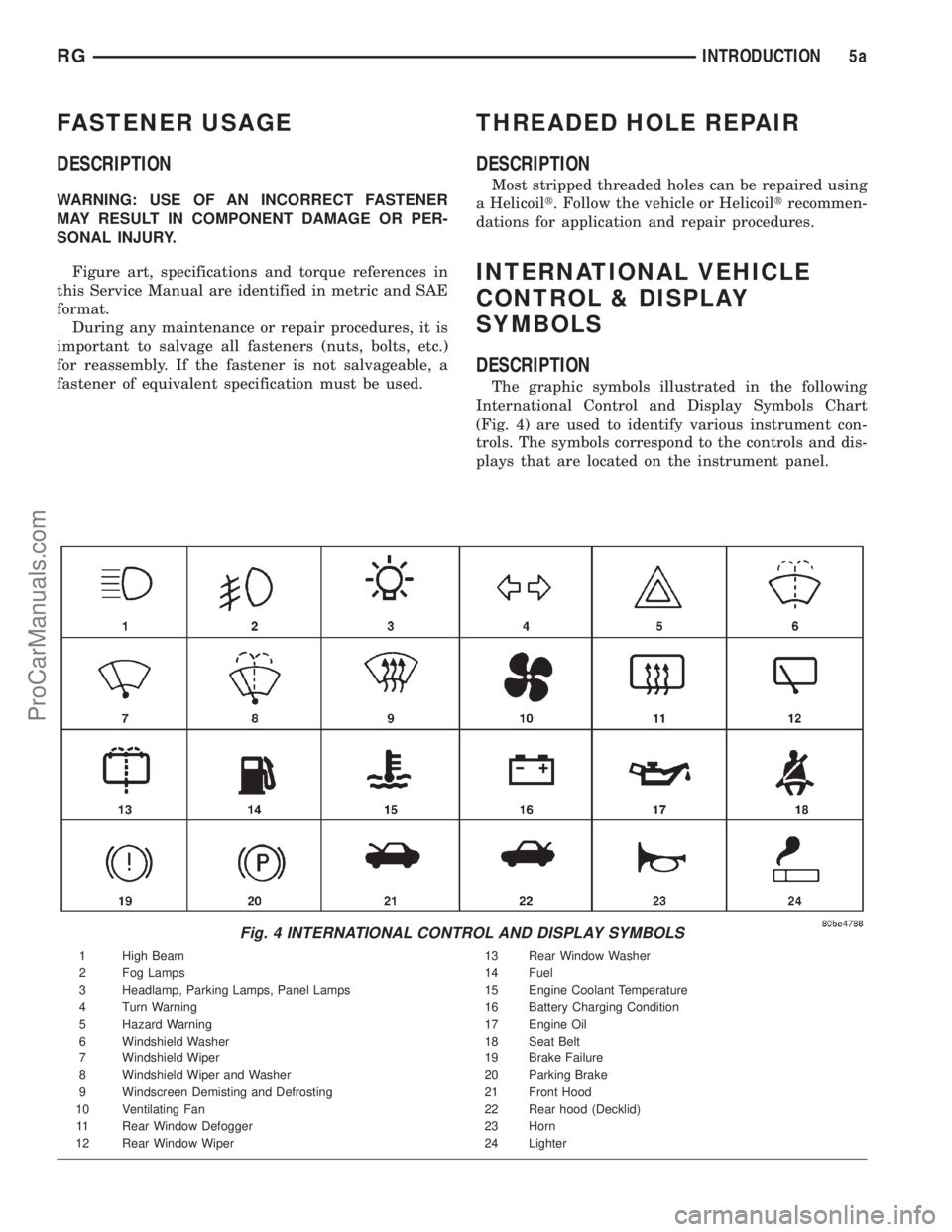
The graphic symbols illustrated in the following
International Control and Display Symbols Chart
(Fig. 4) are used to identify various instrument con-
trols. The symbols correspond to the controls and dis-
plays that are located on the instrument panel.
Fig. 4 INTERNATIONAL CONTROL AND DISPLAY SYMBOLS
1 High Beam 13 Rear Window Washer
2 Fog Lamps 14 Fuel
3 Headlamp, Parking Lamps, Panel Lamps 15 Engine Coolant Temperature
4 Turn Warning 16 Battery Charging Condition
5 Hazard Warning 17 Engine Oil
6 Windshield Washer 18 Seat Belt
7 Windshield Wiper 19 Brake Failure
8 Windshield Wiper and Washer 20 Parking Brake
9 Windscreen Demisting and Defrosting 21 Front Hood
10 Ventilating Fan 22 Rear hood (Decklid)
11 Rear Window Defogger 23 Horn
12 Rear Window Wiper 24 Lighter
RGINTRODUCTION5a
ProCarManuals.com
Page 20 of 2321
VEHICLE IDENTIFICATION
NUMBER
DESCRIPTION
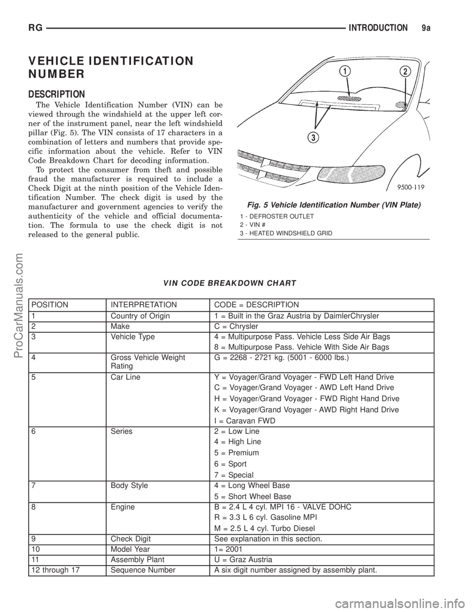
The Vehicle Identification Number (VIN) can be
viewed through the windshield at the upper left cor-
ner of the instrument panel, near the left windshield
pillar (Fig. 5). The VIN consists of 17 characters in a
combination of letters and numbers that provide spe-
cific information about the vehicle. Refer to VIN
Code Breakdown Chart for decoding information.
To protect the consumer from theft and possible
fraud the manufacturer is required to include a
Check Digit at the ninth position of the Vehicle Iden-
tification Number. The check digit is used by the
manufacturer and government agencies to verify the
authenticity of the vehicle and official documenta-
tion. The formula to use the check digit is not
released to the general public.
VIN CODE BREAKDOWN CHART
POSITION INTERPRETATION CODE = DESCRIPTION
1 Country of Origin 1 = Built in the Graz Austria by DaimlerChrysler
2 Make C = Chrysler
3 Vehicle Type 4 = Multipurpose Pass. Vehicle Less Side Air Bags
8 = Multipurpose Pass. Vehicle With Side Air Bags
4 Gross Vehicle Weight
RatingG = 2268 - 2721 kg. (5001 - 6000 lbs.)
5 Car Line Y = Voyager/Grand Voyager - FWD Left Hand Drive
C = Voyager/Grand Voyager - AWD Left Hand Drive
H = Voyager/Grand Voyager - FWD Right Hand Drive
K = Voyager/Grand Voyager - AWD Right Hand Drive
I = Caravan FWD
6 Series 2 = Low Line
4 = High Line
5 = Premium
6 = Sport
7 = Special
7 Body Style 4 = Long Wheel Base
5 = Short Wheel Base
8 Engine B = 2.4 L 4 cyl. MPI 16 - VALVE DOHC
R = 3.3 L 6 cyl. Gasoline MPI
M = 2.5 L 4 cyl. Turbo Diesel
9 Check Digit See explanation in this section.
10 Model Year 1= 2001
11 Assembly Plant U = Graz Austria
12 through 17 Sequence Number A six digit number assigned by assembly plant.
Fig. 5 Vehicle Identification Number (VIN Plate)
1 - DEFROSTER OUTLET
2 - VIN #
3 - HEATED WINDSHIELD GRID
RGINTRODUCTION9a
ProCarManuals.com
Page 198 of 2321
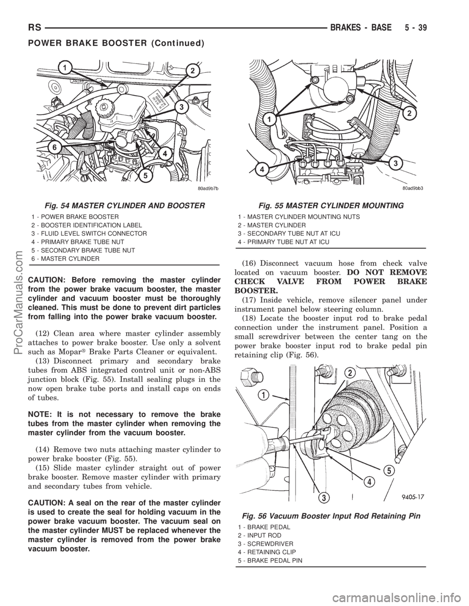
CAUTION: Before removing the master cylinder
from the power brake vacuum booster, the master
cylinder and vacuum booster must be thoroughly
cleaned. This must be done to prevent dirt particles
from falling into the power brake vacuum booster.
(12) Clean area where master cylinder assembly
attaches to power brake booster. Use only a solvent
such as MopartBrake Parts Cleaner or equivalent.
(13) Disconnect primary and secondary brake
tubes from ABS integrated control unit or non-ABS
junction block (Fig. 55). Install sealing plugs in the
now open brake tube ports and install caps on ends
of tubes.
NOTE: It is not necessary to remove the brake
tubes from the master cylinder when removing the
master cylinder from the vacuum booster.
(14) Remove two nuts attaching master cylinder to
power brake booster (Fig. 55).
(15) Slide master cylinder straight out of power
brake booster. Remove master cylinder with primary
and secondary tubes from vehicle.
CAUTION: A seal on the rear of the master cylinder
is used to create the seal for holding vacuum in the
power brake vacuum booster. The vacuum seal on
the master cylinder MUST be replaced whenever the
master cylinder is removed from the power brake
vacuum booster.(16) Disconnect vacuum hose from check valve
located on vacuum booster.DO NOT REMOVE
CHECK VALVE FROM POWER BRAKE
BOOSTER.
(17) Inside vehicle, remove silencer panel under
instrument panel below steering column.
(18) Locate the booster input rod to brake pedal
connection under the instrument panel. Position a
small screwdriver between the center tang on the
power brake booster input rod to brake pedal pin
retaining clip (Fig. 56).
Fig. 54 MASTER CYLINDER AND BOOSTER
1 - POWER BRAKE BOOSTER
2 - BOOSTER IDENTIFICATION LABEL
3 - FLUID LEVEL SWITCH CONNECTOR
4 - PRIMARY BRAKE TUBE NUT
5 - SECONDARY BRAKE TUBE NUT
6 - MASTER CYLINDER
Fig. 55 MASTER CYLINDER MOUNTING
1 - MASTER CYLINDER MOUNTING NUTS
2 - MASTER CYLINDER
3 - SECONDARY TUBE NUT AT ICU
4 - PRIMARY TUBE NUT AT ICU
Fig. 56 Vacuum Booster Input Rod Retaining Pin
1 - BRAKE PEDAL
2 - INPUT ROD
3 - SCREWDRIVER
4 - RETAINING CLIP
5 - BRAKE PEDAL PIN
RSBRAKES - BASE5-39
POWER BRAKE BOOSTER (Continued)
ProCarManuals.com
Page 211 of 2321
(1) Grasp the exposed section of the front parking
brake cable and pull rearward on it. While holding
the park brake in this position, install a pair of lock-
ing pliers on the front parking brake cable just rear-
ward of the second body outrigger bracket (Fig. 76).
(2) Install the equalizer on the front parking brake
cable.
(3) Install the left rear and intermediate park
brake cable in the correct location on the parking
brake cable equalizer (Fig. 77).
(4) Remove the locking pliers from the front park-
ing brake cable. This will allow the adjuster in the
park brake lever (pedal) mechanism to tension the
park brake cables.
(5) Apply and release the parking brake lever
(pedal) one time. This will seat the parking brake
cables and allow the auto adjuster in the parking
brake lever (pedal) mechanism to correctly tension
the parking brake cables.
LEVER - PARKING BRAKE
REMOVAL
(1) Manually release the automatic self-adjusting
mechanism tension of the parking brake lever (pedal)
assembly. (Refer to 5 - BRAKES/PARKING BRAKE -
STANDARD PROCEDURE).
(2) Disconnect negative (ground) cable from the
battery and isolate cable from battery terminal.
(3) Remove sill scuff plate from left door sill.
(4) Remove the left side kick panel.
(5) Remove the silencer panel under the instru-
ment panel.
(6) Remove the steering column cover from the
lower instrument panel.
(7) Remove the reinforcement from the lower
instrument panel.
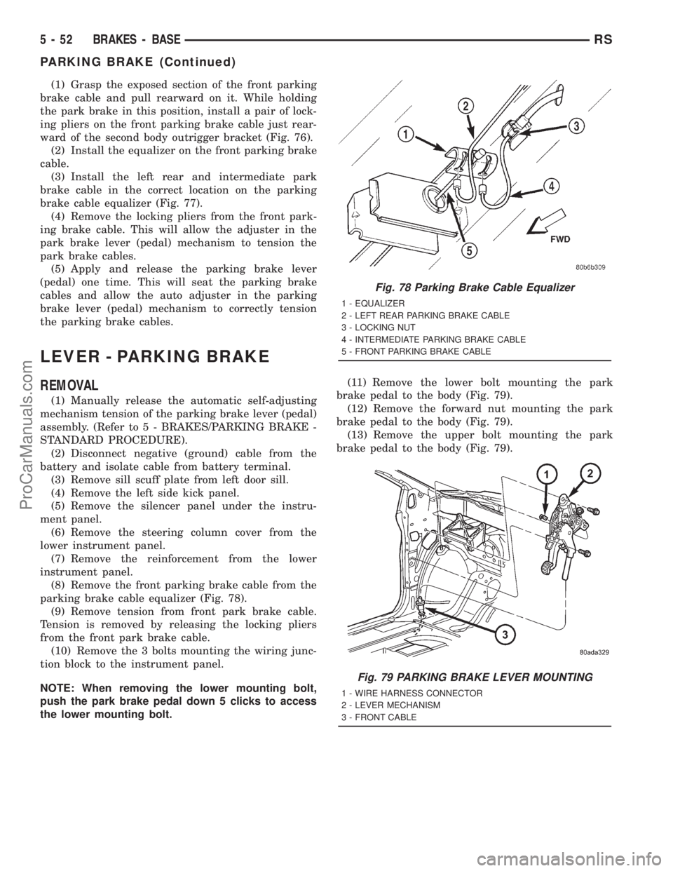
(8) Remove the front parking brake cable from the
parking brake cable equalizer (Fig. 78).
(9) Remove tension from front park brake cable.
Tension is removed by releasing the locking pliers
from the front park brake cable.
(10) Remove the 3 bolts mounting the wiring junc-
tion block to the instrument panel.
NOTE: When removing the lower mounting bolt,
push the park brake pedal down 5 clicks to access
the lower mounting bolt.(11) Remove the lower bolt mounting the park
brake pedal to the body (Fig. 79).
(12) Remove the forward nut mounting the park
brake pedal to the body (Fig. 79).
(13) Remove the upper bolt mounting the park
brake pedal to the body (Fig. 79).
Fig. 78 Parking Brake Cable Equalizer
1 - EQUALIZER
2 - LEFT REAR PARKING BRAKE CABLE
3 - LOCKING NUT
4 - INTERMEDIATE PARKING BRAKE CABLE
5 - FRONT PARKING BRAKE CABLE
Fig. 79 PARKING BRAKE LEVER MOUNTING
1 - WIRE HARNESS CONNECTOR
2 - LEVER MECHANISM
3 - FRONT CABLE
5 - 52 BRAKES - BASERS
PARKING BRAKE (Continued)
ProCarManuals.com
Page 212 of 2321
(14) Pull downward on front park brake cable
while rotating park brake pedal mechanism out from
behind junction block.
(15) Remove park brake pedal release link from
park brake mechanism.
(16) Remove the warning lamp ground switch con-
nector from the park brake pedal mechanism (Fig.
79).
(17) Remove front park brake cable button from
park brake pedal mechanism. Tap end housing for
front park brake cable out of park brake pedal mech-
anism.
INSTALLATION
(1) Install park brake cable end housing into park
brake pedal mechanism.
(2) Install cable retainer onto the park brake cable
strand and then install retainer into pedal bracket.
(3) Install cable strand button into the clevis on
the park brake pedal mechanism.
(4) Install wiring harness connector on warning
indicator lamp ground switch.
(5) Install the park brake release rod on the
release mechanism of the park brake pedal.
(6) Position the park brake pedal mechanism into
its installed position on the body of the vehicle.
(7) Loosely install the top bolt mounting the park
brake pedal mechanism to the body (Fig. 79).
(8) Loosely install the forward nut mounting the
park brake pedal mechanism to the body (Fig. 79).
(9) Loosely install the lower bolt mounting the
park brake pedal mechanism to the body (Fig. 79).
(10) Tighten pedal mechanism attaching bolts and
nut to 28 N´m (250 in. lbs.).
(11) Verify that the park brake pedal is in the fully
released (full up) position.
(12) Raise vehicle.
(13) Install the front park brake cable on the park
brake cable equalizer (Fig. 78).
NOTE: If the original lever assembly is being used,
the lever mechanism auto adjuster spring tension
will need to be reset. (Refer to 5 - BRAKES/PARK-
ING BRAKE - STANDARD PROCEDURE)
(14) Lower vehicle.
(15) Remove the lock-out pin (if a new lever has
been installed) from the automatic cable adjuster on
the park brake pedal mechanism.
(16) Install the electrical junction block on the
instrument panel.
(17) Install the reinforcement on the lower instru-
ment panel.
(18) Install the steering column lower cover on the
lower instrument panel.(19) Install the silencer panel under the instru-
ment panel.
(20) Install the left side kick panel.
(21) Install the sill scuff plate on the lower sill of
the left door.
(22) Install the negative (ground) cable on the bat-
tery.
(23) Cycle the park brake pedal one time. This will
seat the park brake cables and will allow the auto-
matic self adjuster to properly tension the park brake
cables.
SHOES - PARKING BRAKE
REMOVAL
(1) Set the parking brake.The parking brake is
set to keep the hub/bearing and axle shaft from
rotating when loosening the hub nut.
(2) Raise vehicle. (Refer to LUBRICATION &
MAINTENANCE/HOISTING - STANDARD PROCE-
DURE).
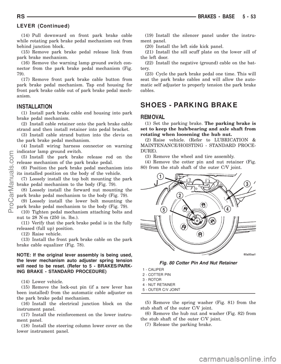
(3) Remove the wheel and tire assembly.
(4) Remove the cotter pin and nut retainer (Fig.
80) from the stub shaft of the outer C/V joint.
(5) Remove the spring washer (Fig. 81) from the
stub shaft of the outer C/V joint.
(6) Remove the hub nut and washer (Fig. 82) from
the stub shaft of the outer C/V joint.
(7) Release the parking brake.
Fig. 80 Cotter Pin And Nut Retainer
1 - CALIPER
2 - COTTER PIN
3 - ROTOR
4 - NUT RETAINER
5 - OUTER C/V JOINT
RSBRAKES - BASE5-53
LEVER (Continued)
ProCarManuals.com
Page 237 of 2321
(2) Inside the vehicle, install the remaining 2
mounting bolts attaching the ICU to the mounting
bracket (Fig. 11). Tighten all 3 mounting bolts to a
torque of 11 N´m (97 in. lbs.).
(3) Install the dash seal and three mounting
screws (Fig. 10).
(4) Install the silencer on top of the dash seal (Fig.
10).
(5) Connect the steering shaft coupling and install
the pinch bolt (Fig. 10). Tighten the pinch bolt to 28
N´m (250 in. lbs.).
(6) Install the silencer panel below the steering
column under the instrument panel.
(7) Remove the steering wheel holder.
CAUTION: Because of the flexible section in the pri-
mary and secondary brake tubes, the brake tubes
must be held in proper orientation when tightened
and torqued. These tubes must not contact each
other or other vehicle components when installed.
Also, after the brake tubes are installed on the HCU,
ensure all spacer clips are reinstalled on the brake
tubes.
(8) Install the primary and secondary brake tubes
into their correct port locations on the HCU valve
block (Fig. 9). Tighten the tube nuts to a torque of 17
N´m (145 in. lbs.).
CAUTION: When installing the chassis brake tubes
on the HCU valve block, they must be located cor-
rectly in the valve block to ensure proper ABS oper-
ation.
NOTE: The chassis brake tube attachment locations
to the HCU, are marked on the bottom of the CAB.
(9) Install the (4) chassis brake tubes into their
correct port locations on the HCU valve block as
shown (Fig. 9). Tighten the tube nuts to a torque of
17 N´m (145 in. lbs.).NOTE: Before installing the 24±way connector in
the CAB be sure the seal is properly installed in the
connector.
(10) Install the 24±way connector on the CAB by,
first, positioning the 24±way connector in the socket
of the CAB and carefully pushing it down as far as
possible. Once connector is fully seated by hand into
the CAB socket, push down on connector lock. This
will pull the connector into the socket of the CAB
and lock it in the installed position.
(11) Install any routing clips on the brake tubes.
(12) Remove the brake pedal holder.
(13) Install the speed control servo with its mount-
ing nuts.
(14) Connect the wiring harness to the speed con-
trol servo.
(15) Install the battery tray (Refer to 8 - ELEC-
TRICAL/BATTERY SYSTEM/TRAY - INSTALLA-
TION).
(16) Install the screw securing the coolant filler
neck to the battery tray.
(17) Reconnect the vacuum hose connector at the
tank built into the battery tray.
(18) Install the battery (Refer to 8 - ELECTRI-
CAL/BATTERY SYSTEM/BATTERY - INSTALLA-
TION).
(19) Install the battery shield.
(20) Remove the brake pedal holder.
(21) Connect negative cable back on negative post
of the battery.
(22) Bleed the Base and ABS brake hydraulic sys-
tems (Refer to 5 - BRAKES - STANDARD PROCE-
DURE).
(23) Road test vehicle to ensure proper operation
of the base and antilock brake systems.
5 - 78 BRAKES - ABSRS
ICU (INTEGRATED CONTROL UNIT) (Continued)
ProCarManuals.com