2001 DODGE TOWN AND COUNTRY fuses
[x] Cancel search: fusesPage 228 of 2321
the rear brake pressure, the outlet valve is switched
off and the inlet valve is pulsed. This increases the
pressure to the rear brakes. This back-and-forth pro-
cess will continue until the required slip difference is
obtained. At the end of EBD braking (brakes
released) the fluid in the LPA drains back to the
master cylinder by switching on the outlet valve and
draining through the inlet valve check valve. At the
same time the inlet valve is switched on in case of
another brake application.
The EBD will remain functional during many ABS
fault modes. If both the red BRAKE, and amber ABS
warning indicators are illuminated, the EBD may not
be functioning.
OPERATION - TRACTION CONTROL SYSTEM
The traction control module monitors wheel speed.
During acceleration, if the module detects front
(drive) wheel slip and the brakes are not applied, the
module enters traction control mode. Traction control
operation proceeds in the following order:
(1) Close the normally open isolation valves.
(2) Start the pump/motor and supply volume and
pressure to the front (drive) hydraulic circuit. (The
pump/motor runs continuously during traction con-
trol operation.)
(3) Open and close the build and decay valves to
maintain minimum wheel slip and maximum trac-
tion.
The cycling of the build and decay valves during
traction control is similar to that during antilock
braking, except the valves work to control wheel spin
by applying the brakes, whereas the ABS function is
to control wheel skid by releasing the brakes.
If the brakes are applied at anytime during a trac-
tion control cycle, the brake lamp switch triggers the
controller to switch off traction control.
HYDRAULIC SHUTTLE VALVES
Two pressure relief hydraulic shuttle valves allow
pressure and volume to return to the master cylinder
reservoir when not consumed by the build and decay
valves. These valves are necessary because the
pump/motor supplies more volume than the system
requires.
TRACTION CONTROL LAMP
The traction control system is enabled at each igni-
tion cycle. It may be turned off by depressing the
Traction Control Off switch button when the ignition
is in the ON position. The traction control function
lamp (TRAC OFF) illuminates immediately upon
depressing the button.
The traction control function lamp illuminates dur-
ing a traction control cycle, displaying TRAC.If the CAB calculates that the brake temperatures
are high, the traction control system becomes inoper-
ative until a time-out period has elapsed. During this
ªthermo-protection mode,º the traction control func-
tion lamp illuminates TRAC OFF; note that no trou-
ble code is registered.
CAUTION
The ABS uses an electronic control module, the
CAB. This module is designed to withstand normal
current draws associated with vehicle operation.
Care must be taken to avoid overloading the CAB
circuits.
CAUTION: In testing for open or short circuits, do
not ground or apply voltage to any of the circuits
unless instructed to do so for a diagnostic proce-
dure.
CAUTION: These circuits should only be tested
using a high impedance multi-meter or the DRBIIIT
scan tool as described in this section. Power
should never be removed or applied to any control
module with the ignition in the ON position. Before
removing or connecting battery cables, fuses, or
connectors, always turn the ignition to the OFF
position.
CAUTION: The CAB 24-way connector should never
be connected or disconnected with the ignition
switch in the ON position.
CAUTION: Use only factory wiring harnesses. Do
not cut or splice wiring to the brake circuits. The
addition of aftermarket electrical equipment (car
phone, radar detector, citizen band radio, trailer
lighting, trailer brakes, etc.) on a vehicle equipped
with antilock brakes may affect the function of the
antilock brake system.
CAUTION: When performing any service procedure
on a vehicle equipped with ABS, do not apply a
12-volt power source to the ground circuit of the
pump motor in the HCU. Doing this will damage the
pump motor and will require replacement of the
entire HCU.
CAUTION: An attempt to remove or disconnect cer-
tain system components may result in improper
system operation. Only those components with
approved removal and installation procedures in
this manual should be serviced.
RSBRAKES - ABS5-69
BRAKES - ABS (Continued)
ProCarManuals.com
Page 339 of 2321
AUDIO SYSTEM DIAGNOSIS
CONDITION POSSIBLE CAUSE CORRECTION
NO AUDIO. 1. FUSE FAULTY. 1. CHECK RADIO FUSES IN FUSE BLOCK MODULE.
REPLACE FUSES, IF REQUIRED.
2. RADIO CONNECTOR
FAULTY.2. CHECK FOR LOOSE OR CORRODED RADIO CONNECTOR.
REPAIR, IF REQUIRED.
3. WIRING FAULTY. 3. CHECK FOR BATTERY VOLTAGE AT RADIO CONNECTOR.
REPAIR WIRING, IF REQUIRED.
4. GROUND FAULTY. 4. CHECK FOR CONTINUITY BETWEEN RADIO CHASSIS AND
A KNOWN GOOD GROUND. THERE SHOULD BE
CONTINUITY. REPAIR GROUND, IF REQUIRED.
5. RADIO FAULTY. 5. EXCHANGE OR REPLACE RADIO, IF REQUIRED.
6. SPEAKERS FAULTY. 6. SEE SPEAKER DIAGNOSIS, IN THIS GROUP.
NO DISPLAY. 1. FUSE FAULTY. 1. CHECK RADIO FUSES IN FUSE BLOCK MODULE.
REPLACE FUSES, IF REQUIRED.
2. RADIO CONNECTOR
FAULTY.2. CHECK FOR LOOSE OR CORRODED RADIO CONNECTOR.
REPAIR, IF REQUIRED.
3. WIRING FAULTY. 3. CHECK FOR BATTERY VOLTAGE AT RADIO CONNECTOR.
REPAIR WIRING, IF REQUIRED.
4. GROUND FAULTY. 4. CHECK FOR CONTINUITY BETWEEN RADIO CHASSIS AND
A KNOWN GOOD GROUND. THERE SHOULD BE
CONTINUITY. REPAIR GROUND, IF REQUIRED.
5. RADIO FAULTY. 5. EXCHANGE OR REPLACE RADIO, IF REQUIRED.
NO MEMORY. 1. FUSE FAULTY. 1. CHECK IGNITION-OFF DRAW FUSE. REPLACE FUSE, IF
REQUIRED.
2. RADIO CONNECTOR
FAULTY.2. CHECK FOR LOOSE OR CORRODED RADIO CONNECTOR.
REPAIR, IF REQUIRED.
3. WIRING FAULTY. 3. CHECK FOR BATTERY VOLTAGE AT RADIO CONNECTOR.
REPAIR WIRING, IF REQUIRED.
4. GROUND FAULTY. 4. CHECK FOR CONTINUITY BETWEEN RADIO CHASSIS AND
A KNOWN GOOD GROUND. THERE SHOULD BE
CONTINUITY. REPAIR GROUND, IF REQUIRED.
5. RADIO FAULTY. 5. EXCHANGE OR REPLACE RADIO, IF REQUIRED.
POOR RADIO
RECEPTION.1. ANTENNA FAULTY. 1. SEE ANTENNA DIAGNOSIS, IN THIS GROUP. REPAIR OR
REPLACE ANTENNA, IF REQUIRED.
2. GROUND FAULTY. 2. CHECK FOR CONTINUITY BETWEEN RADIO CHASSIS AND
A KNOWN GOOD GROUND. THERE SHOULD BE
CONTINUITY. REPAIR GROUND, IF REQUIRED.
3. RADIO FAULTY. 3. EXCHANGE OR REPLACE RADIO, IF REQUIRED.
8A - 2 AUDIORS
AUDIO (Continued)
ProCarManuals.com
Page 475 of 2321
LAMPS/LIGHTING - EXTERIOR
DESCRIPTION
LAMP SYSTEMS
RS vehicles use lighting on the interior and exte-
rior of the vehicle for illuminating and indicating
purposes. Lighting circuits are protected by fuses.
Lighting circuits require an overload protected power
source, on/off device, lamps and body ground to oper-
ate properly. Plastic lamps require a wire in the har-
ness to supply body ground to the lamp socket.
Replace sockets and bulbs that are corroded.
Some of the interior and exterior lighting functions
are governed by the Body Control Module. The head-
lamp, dome, and the door ajar switches provide sig-
nals to the Body Control Module. The Body Control
Module in turn sends a J1850 message to the Front
Control Module (FCM) to enable the necessary driv-
ers to set the required illumination configuration.
Wire connectors can make intermittent contact or
become corroded. Before coupling wire connectors,
inspect the terminals inside the connector. Male termi-
nals should not be bent or disengaged from the insu-
lator. Female terminals should not be sprung open or
disengaged from the insulator. Bent and sprung termi-
nals can be repaired using needle nose pliers and pick
tool. Corroded terminals appear chalky or green. Cor-
roded terminals should be replaced to avoid recur-
rence of the problem symptoms.
Begin electrical system failure diagnosis by testing
related fuses in the fuse block and intelligent power
module. Verify that bulbs are in good condition and
test continuity of the circuit ground. Refer to the
appropriate wiring information. The wiring informa-
tion includes wiring diagrams, proper wire and con-
nector repair procedures, details of wire harness
routing and retention, connector pin-out information
and location views for the various wire harness con-
nectors, splices and grounds.
AUTOMATIC HEADLAMP SYSTEM
The Automatic Headlamp system turns the instru-
mentation and exterior illumination lamps ON when
the ambient light levels are Night and OFF when
light levels are Day.
DAYTIME RUNNING LAMPS
Operating the high-beam headlamps at reduced
power provides daytime running lamps, which are
required on all new Canadian vehicles.
HEADLAMPS ON WITH WINDSHIELD WIPERS
For vehicles equipped with the Automatic Head-
lamp System, the instrumentation and exterior illu-
mination lamps will be turned ON when theheadlamp switch is in the AUTO position, RPM >
450 and the windshield wipers have been in the
intermittent, low or high mode of operation for more
than ten seconds. When the windshield wipers are
turned OFF the Body Control Module will determine
if the instrumentation and exterior illumination
lamps should remain ON base upon the current
ambient light level.
HEADLAMP SYSTEM
The configuration of the headlamp system of head-
lamps, park lamps and fog lamps is determined by
the BCM. The BCM determines the lighting configu-
ration as a result of the inputs from the ignition
switch, headlamp switch and multifunction switch. A
J1850 is transmitted from the BCM to the FCM to
enable the necessary drivers to set the illumination
configuration. Four wires are connected between the
headlamp switch and the BCM. The first wire con-
tains information regarding the position of the head-
lamp switch (Off, Automatic Headlamps, Automatic
Headlamp switch fog, Park with Fog, Head, or Head
with Fog Lamps). The second wire contains informa-
tion regarding the position of the dimmer switch
(Dome Lamp, Daytime Brightness, Dimming Level or
Off). The third wire is a dedicated signal return
(ground) wire. The fourth wire provides power to the
front fog lamp indicator.
HEADLAMP TIME DELAY SYSTEM
The headlamp time delay system is controlled by
the Body Control Module (BCM) via a J1850 message
transmitted by the BCM to the FCM to turn off the
headlamps.
OPERATION
AUTOMATIC HEADLAMP SYSTEM
Automatic headlamps are controlled by the Body
Control Module (BCM). With the headlamp switch in
the AUTO position, the BCM will control the head-
lamp, parking, side marker, tail and instrumentation
lamps based on ambient light levels. Ambient light
levels are monitored by the BCM using the Day/
Night signal and Electrochromatic Mirror (ECM)
present from the Compass Mini Trip (CMTC) located
on the front windshield in front of the rear view mir-
ror (ECM). Ambient light readings are averaged to
limit cycling the lamps ON and OFF when passing
through areas with varying light levels. The auto-
matic headlamps will only function when the engine
is running with RPM > 450. When the headlamp
switch is in the AUTO position (Automatic mode), the
Headlamp Time Delay system will function when the
ignition switch is placed in any position other than
run/start.
8L - 2 LAMPS/LIGHTING - EXTERIORRS
ProCarManuals.com
Page 476 of 2321
DAYTIME RUNNING LAMPS
Power is reduced using pulse-width modulation to
the high beams, where by the power is switched on
and off rapidly instead of remaining on continuously.
The duration and interval of the power pulses is pro-
grammed into the Front Control Module (FCM).
HEADLAMP SYSTEM
The headlamp system will default to headlamps
ON position when ignition switch is ON and when an
open or short circuit failure occurs on the headlamp
switch input. The system will return to normal oper-
ation when the open or short is repaired. A fault will
be reported by the BCM when a failure occurs on the
dimmer or headlamp switch input.
If the exterior lamps are ON and the headlamp
switch is in any position other than OFF or AUTO
and with the ignition switch OFF (LOCK) after 3
minutes the BCM sends a message via J1850 to the
FCM informing the FCM to turn off the headlamps,
park lamps and fog lamps. This feature prevents the
vehicle battery from being discharged when the vehi-
cle lights have been left ON.
HEADLAMP TIME DELAY SYSTEM
The headlamp time delay system is activated by
turning the headlamps ON (high or low beam) while
the engine is running, turning the ignition switch
OFF, and then turning the headlamp switch OFF
within 45 seconds. The system will not activate if
more than 45 seconds elapse between ignition switch
OFF and headlamp switch OFF. The BCM will allow
the headlamps to remain ON for 90 seconds (config-
urable) before they automatically turn off (If the key
is in the ignition during the headlamp time delay
mode, then both the headlamps and park lamps
(including panel dimming) will be ON). Refer to the
Owner's Manual for more information.
If the headlamp switch is in the Auto Headlamp
Position, the headlamps are ON due to the night sig-
nal from the CMTC and the ignition switch is in any
position other than run/start, the BCM shall enter a
90 second (configurable) Auto Headlamps time delay
mode. If the key is in the ignition during the head-
lamp time delay mode, then both the headlamps and
park lamps (including panel dimming) will be ON. If
the key is not in the ignition, then only the head-
lamps will be ON. The BCM will allow the head-
lamps to remain ON for 90 seconds before they
automatically turn OFF. Refer to the Owner's Man-
ual for more information.
LAMP OUTAGE
If one or more of the following lamps (Low and/or
High beams) are out, then a ªlamps outº indicator
located in the cluster will illuminate.
OPTICAL HORN/HIGH BEAMS
When the multifunction switch is pulled to the first
detent (optical horn) signal, the headlamps are ON,
key-in the ignition the BCM shall send a message via
J1850 to the FCM to turn on the headlamps drivers
to illuminate all four filaments (Low and High
beams). When the multifunction switch is pulled to
the second detent (high beam) signal and the head-
lamps are ON, the BCM shall send a message via
J1850 to the FCM to turn on the headlamps drivers.
The High Beams are illuminated and the Low Beams
and Fog Lamps (if ON) are extinguished. If the head-
lamps were in the high beam configuration when
power was removed from the headlamps, the head-
lamps will be configured as low beam the next time
they are activated.
DIAGNOSIS AND TESTING
WARNING: EYE PROTECTION SHOULD BE USED
WHEN SERVICING GLASS COMPONENTS. PER-
SONAL INJURY CAN RESULT.
CAUTION: Do not touch the glass of halogen bulbs
with fingers or other possibly oily surface, reduced
bulb life will result. Do not use bulbs other than
those indicated in the Bulb Application table. Dam-
age to lamp and/or Daytime Running Lamp Module
can result. Do not use fuses, circuit breakers or
relays having greater amperage value than indi-
cated on the fuse panel or in the Owners Manual.
When a vehicle experiences problems with the
headlamp system, verify the condition of the battery
connections, fuses, charging system, headlamp bulbs,
wire connectors, relay, high beam switch, dimmer
switch, and headlamp switch. Refer to the appropri-
ate wiring information. The wiring information
includes wiring diagrams, proper wire and connector
repair procedures, details of wire harness routing
and retention, connector pin-out information and
location views for the various wire harness connec-
tors, splices and grounds.
Each vehicle is equipped with various lamp assem-
blies. A good ground is necessary for proper lighting
operation. Grounding is provided by the lamp socket
when it comes in contact with the metal body, or
through a separate ground wire.
When changing lamp bulbs check the socket for
corrosion. If corrosion is present, clean it with a wire
brush.
When it is necessary to remove components to ser-
vice another, it should not be necessary to apply
excessive force or bend a component to remove it.
Before damaging a trim component, verify hidden
fasteners or captured edges are not holding the com-
ponent in place.
RSLAMPS/LIGHTING - EXTERIOR8L-3
LAMPS/LIGHTING - EXTERIOR (Continued)
ProCarManuals.com
Page 564 of 2321
trically and independently using the separate power
seat switches found on the outboard seat cushion
side shield of each front seat. See the owner's manual
in the vehicle glove box for more information on the
features, use and operation of the power seat system.
OPERATION - MEMORY SYSTEM
The Memory Seat/Mirror Module (MSMM) will
drive a maximum of 2 motors at a time in a given
direction. If conflicting directions are requested, the
priority for response will be as follows:
²Seat Track Rearward
²Seat Front Down
²Seat Rear Down
²Recliner Rearward
²Seat Track Forward
²Seat Front Up
²Seat Rear Up
²Recliner Forward
The inputs from these switches to the MSMM is a
current limited battery source fed by the MSMM.
This protects the MSMM printed circuit board traces
from acting as fuses. All of these switch contact
inputs to the MSMM are normally closed to ground,
except when actuated.
Soft stops are incorporated to prevent the motor
from being driven into a stall. Should the seat have
restricted travel, refer to Resetting Soft Stops in this
section.
See the owner's manual in the vehicle glove box for
more information on the features, use and operation
of the memory system. For diagnosis of the MSM, the
PCI data bus, or the other electronic modules on the
PCI data bus that provide inputs and outputs for the
memory system, the use of a DRBtscan tool and the
proper Diagnostic Procedures manual are recom-
mended.
ELECTRONIC VEHICLE INFORMATION CENTER
The Electronic Vehicle Information Center (EVIC)
serves as the user interface for the memory system.
It displays memory system status messages and pro-
vides the user with the means for enabling and dis-
abling the many customer programmable features
available on the vehicle, including those for the mem-
ory system.
See the owner's manual in the vehicle glove box for
more information on the features, use and operation
of the EVIC. Refer toElectronic Vehicle Informa-
tion Centerin Overhead Console Systems for more
information on the EVIC.
DIAGNOSIS AND TESTING - POWER SEAT
SYSTEM
Following are tests that will help to diagnose the
hard wired components and circuits of the power seatsystem. However, if the vehicle is also equipped with
the optional memory system, these tests may not
prove conclusive in the diagnosis of the driver side
power seat. In order to obtain conclusive testing of
the driver side power seat with the memory system
option, the Programmable Communications Interface
(PCI) data bus network and all of the electronic mod-
ules that provide inputs to, or receive outputs from
the memory system components must be checked.
The most reliable, efficient, and accurate means to
diagnose the driver side power seat with the memory
system option requires the use of a DRBtscan tool
and the proper Diagnostic Procedures manual. The
DRBtscan tool can provide confirmation that the
PCI data bus is functional, that all of the electronic
modules are sending and receiving the proper mes-
sages on the PCI data bus, and that the memory sys-
tem is receiving the proper hard wired inputs and
relaying the proper hard wired outputs to perform its
driver side power seat functions.
WARNING: SOME VEHICLES ARE EQUIPPED WITH
SEATBACK MOUNTED AIRBAGS (Fig. 1). BEFORE
ATTEMPTING TO DIAGNOSE OR SERVICE ANY
SEAT OR POWER SEAT SYSTEM COMPONENT
YOU MUST FIRST DISCONNECT AND ISOLATE THE
BATTERY NEGATIVE CABLE. THEN WAIT TWO MIN-
UTES FOR THE SYSTEM CAPACITOR TO DIS-
CHARGE BEFORE FURTHER SYSTEM SERVICE.
THIS IS THE ONLY SURE WAY TO DISABLE THE
AIRBAG SYSTEM. FAILURE TO DO SO COULD
RESULT IN ACCIDENTAL AIRBAG DEPLOYMENT
AND POSSIBLE PERSONAL INJURY.
Before any testing of the power seat system is
attempted, the battery should be fully-charged and
all of the power seat system wire harness connections
and pins cleaned and tightened to ensure proper cir-
cuit continuity and ground paths. For complete cir-
cuit diagrams, refer toPower Seatin Wiring
Diagrams.
With the dome lamp on, apply the power seat
switch in the direction of the failure. If the dome
lamp dims, the seat may be jamming. Check under
and behind the seat for binding or obstructions. If
the dome lamp does not dim, proceed with testing of
the individual components and circuits.
DIAGNOSIS AND TESTING - MEMORY SYSTEM
CHECK AND RESET SOFT STOPS
To check and reset the power memory seat soft
stops, use the power seat control switches to move
the seat in one direction to the end of travel, allow a
couple of seconds before re-energizing the seat in the
same direction until it stops and for three additional
seconds after it stops. (The amount the seat moved
RSPOWER SEATS8N-51
POWER SEATS (Continued)
ProCarManuals.com
Page 604 of 2321
NOTE: The following tests may not prove conclu-
sive in the diagnosis of this system. The most reli-
able, efficient, and accurate means to diagnose the
Sentry Key Immobilizer System involves the use of
a DRB IIITscan tool. Refer to the proper Body Diag-
nostic Procedures Manual.
The Sentry Key Immobilizer System (SKIS) and
the Programmable Communication Interface (PCI)
bus network should be diagnosed using a DRB IIIt
scan tool. The DRB IIItwill allow confirmation that
the PCI bus is functional, that the Sentry Key Immo-
bilizer Module (SKIM) is placing the proper messages
on the PCI bus, and that the Powertrain Control
Module (PCM) is receiving the PCI bus messages.
Refer to the proper Body Diagnostic Procedures man-
ual, and Wiring Diagrams for complete circuit
descriptions and diagrams.
(1) Check the fuses in the Integrated Power Mod-
ule (IPM). If OK, go to Step 2. If not OK, repair the
shorted circuit or component as required and replace
the faulty fuse.
(2) Disconnect and isolate the battery negative
remote cable from the remote terminal. Unplug the
wire harness connector at the SKIM. Check for con-
tinuity between the ground circuit cavity of the
SKIM wire harness connector and a good ground.
There should be continuity. If OK, go to Step 3. If not
OK, repair the open circuit to ground as required.
(3) Connect the battery negative cable. Check for
battery voltage at the fused B(+) circuit cavity of the
SKIM wire harness connector. If OK, go to Step 4. If
not OK, repair the open circuit to the fuse in the
IPM as required.
(4) Turn the ignition switch to the ON position.
Check for battery voltage at the fused ignition switch
output (run/start) circuit cavity of the SKIM wire
harness connector. If OK, use a DRB IIItscan tool
and the proper Body Diagnostic Procedures manual
to complete the diagnosis of the SKIS. If not OK,
repair the open circuit to the fuse in the IPM as
required.
DIAGNOSIS AND TESTING - VEHICLE THEFT
SECURITY SYSTEM
Refer to the appropriate wiring information. The
wiring information includes wiring diagrams, proper
wire and connector repair procedures, further details
on wire harness routing and retention, as well as
pin-out and location views for the various wire har-
ness connectors, splices and grounds. Using a DRB
IIItscan tool. Refer to the proper Body Diagnostic
Procedures Manual for test procedures.
HOOD AJAR SWITCH
REMOVAL
(1) Disconnect and isolate the battery negative
cable.
(2) Using a small flat blade screwdriver, pry trig-
ger switch from the bracket on the left fender well.
(3) Disconnect the hood ajar switch from the wire
connector and remove from vehicle.
INSTALLATION
(1) Connect the hood ajar switch to the wire conec-
tor.
(2) Press the hood ajar switch into position on the
bracket located on the left inner fender well.
(3) Reconnect the battery negative cable.
(4) Close the hood and check for proper operation.
TRANSPONDER KEY
DESCRIPTION
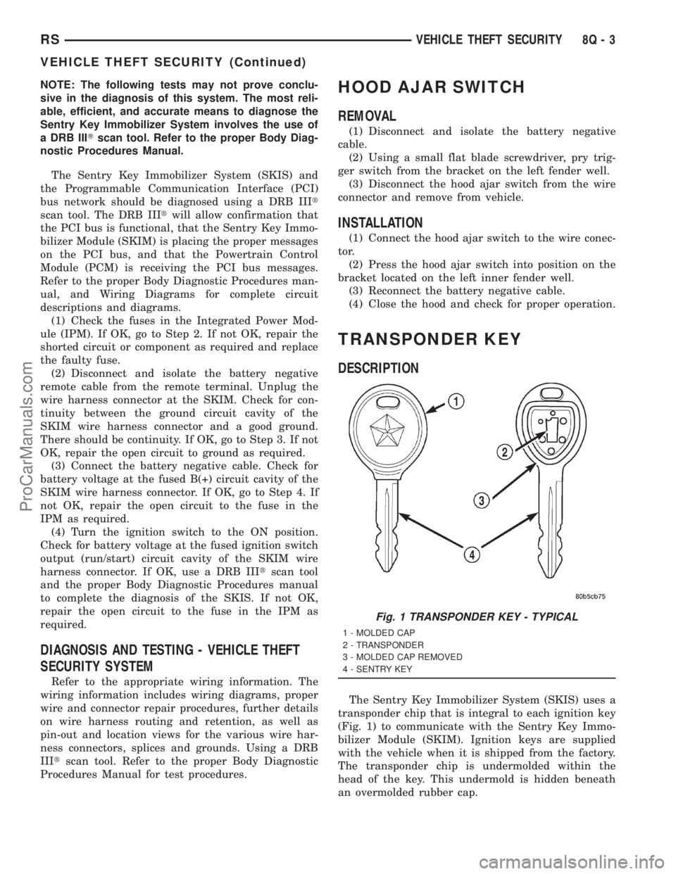
The Sentry Key Immobilizer System (SKIS) uses a
transponder chip that is integral to each ignition key
(Fig. 1) to communicate with the Sentry Key Immo-
bilizer Module (SKIM). Ignition keys are supplied
with the vehicle when it is shipped from the factory.
The transponder chip is undermolded within the
head of the key. This undermold is hidden beneath
an overmolded rubber cap.
Fig. 1 TRANSPONDER KEY - TYPICAL
1 - MOLDED CAP
2 - TRANSPONDER
3 - MOLDED CAP REMOVED
4 - SENTRY KEY
RSVEHICLE THEFT SECURITY8Q-3
VEHICLE THEFT SECURITY (Continued)
ProCarManuals.com
Page 620 of 2321
8W-01 WIRING DIAGRAM INFORMATION
TABLE OF CONTENTS
page page
WIRING DIAGRAM INFORMATION
DESCRIPTION............................1
WARNING...............................5
DIAGNOSIS AND TESTING..................5
WIRING HARNESS......................5
STANDARD PROCEDURE...................6
TESTING OF VOLTAGE POTENTIAL.........6
TESTING FOR CONTINUITY...............6
TESTING FOR SHORT TO GROUND.........6
TESTING FOR A SHORT TO GROUND ON
FUSES POWERING SEVERAL LOADS........7
TESTING FOR VOLTAGE DROP............7
SPECIAL TOOLS..........................8
CONNECTOR - AUGAT
REMOVAL...............................8
INSTALLATION............................8CONNECTOR - MOLEX
REMOVAL...............................9
INSTALLATION............................9
CONNECTOR - THOMAS AND BETTS
REMOVAL...............................9
INSTALLATION...........................10
DIODE
REMOVAL..............................10
INSTALLATION...........................10
TERMINAL
REMOVAL..............................11
INSTALLATION...........................11
WIRE
STANDARD PROCEDURE..................11
STANDARD PROCEDURE - WIRE SPLICING . . 11
WIRING DIAGRAM
INFORMATION
DESCRIPTION - HOW TO USE WIRING
DIAGRAMS
DaimlerChrysler Corporation wiring diagrams are
designed to provide information regarding the vehi-
cles wiring content. In order to effectively use the
wiring diagrams to diagnose and repair
DaimlerChrysler Corporation vehicles, it is important
to understand all of their features and characteris-
tics.
Diagrams are arranged such that the power (B+)
side of the circuit is placed near the top of the page,
and the ground (B-) side of the circuit is placed near
the bottom of the page (Fig. 1).
All switches, components, and modules are shown
in the at rest position with the doors closed and the
key removed from the ignition (Fig. 2).Components are shown two ways. A solid line
around a component indicates that the component is
complete. A dashed line around the component indi-
cates that the component is being shown is not com-
plete. Incomplete components have a reference
number to indicate the page where the component is
shown complete.
It is important to realize that no attempt is made
on the diagrams to represent components and wiring
as they appear on the vehicle. For example, a short
piece of wire is treated the same as a long one. In
addition, switches and other components are shown
as simply as possible, with regard to function only.
SYMBOLS
International symbols are used throughout the wir-
ing diagrams. These symbols are consistent with
those being used around the world (Fig. 3).
RG8W-01 WIRING DIAGRAM INFORMATION8Wa-01-1
ProCarManuals.com
Page 626 of 2321
(4) If the voltmeter registers voltage or the test
lamp glows, there is a short to ground in that gen-
eral area of the wiring harness.
STANDARD PROCEDURE - TESTING FOR
SHORT TO GROUND ON FUSES POWERING
SEVERAL LOADS
(1) Refer to the wiring diagrams and disconnect or
isolate all items on the suspected fused circuits.
(2) Replace the blown fuse.
(3) Supply power to the fuse by turning ON the
ignition switch or re-connecting the battery.
(4) Start connecting the items in the fuse circuit
one at a time. When the fuse blows the circuit with
the short to ground has been isolated.
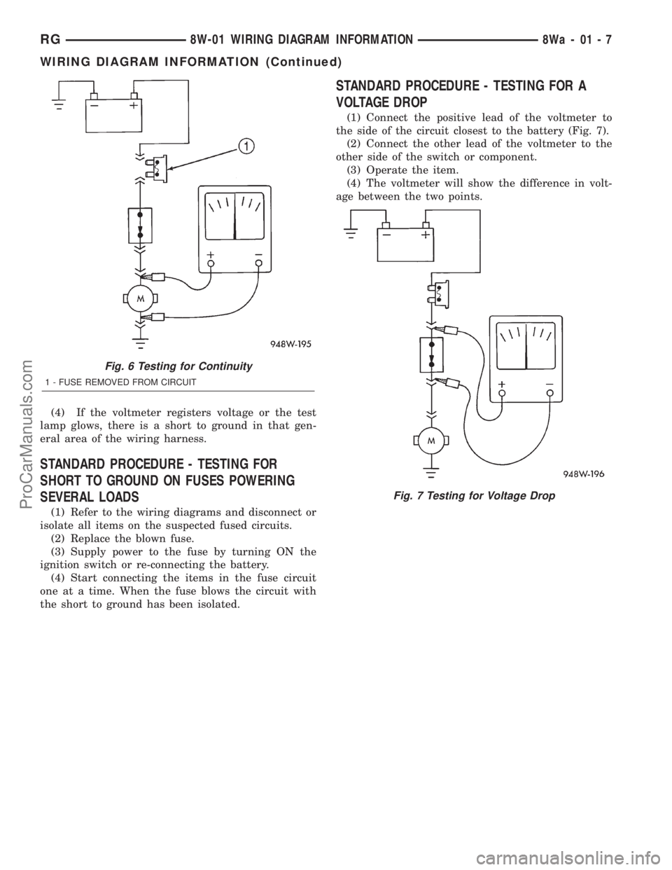
STANDARD PROCEDURE - TESTING FOR A
VOLTAGE DROP
(1) Connect the positive lead of the voltmeter to
the side of the circuit closest to the battery (Fig. 7).
(2) Connect the other lead of the voltmeter to the
other side of the switch or component.
(3) Operate the item.
(4) The voltmeter will show the difference in volt-
age between the two points.
Fig. 6 Testing for Continuity
1 - FUSE REMOVED FROM CIRCUIT
Fig. 7 Testing for Voltage Drop
RG8W-01 WIRING DIAGRAM INFORMATION8Wa-01-7
WIRING DIAGRAM INFORMATION (Continued)
ProCarManuals.com